windshield wipers CHRYSLER VOYAGER 2004 User Guide
[x] Cancel search | Manufacturer: CHRYSLER, Model Year: 2004, Model line: VOYAGER, Model: CHRYSLER VOYAGER 2004Pages: 2585, PDF Size: 62.54 MB
Page 696 of 2585
(4) Repeat Step 1, and align as necessary until
wiper stops chattering and wipes the windshield
clear.
REMOVAL
CAUTION: The driver side wiper arm must be
parked above the passenger side. Failure to do so
will result in damage to the arms, blades or system.
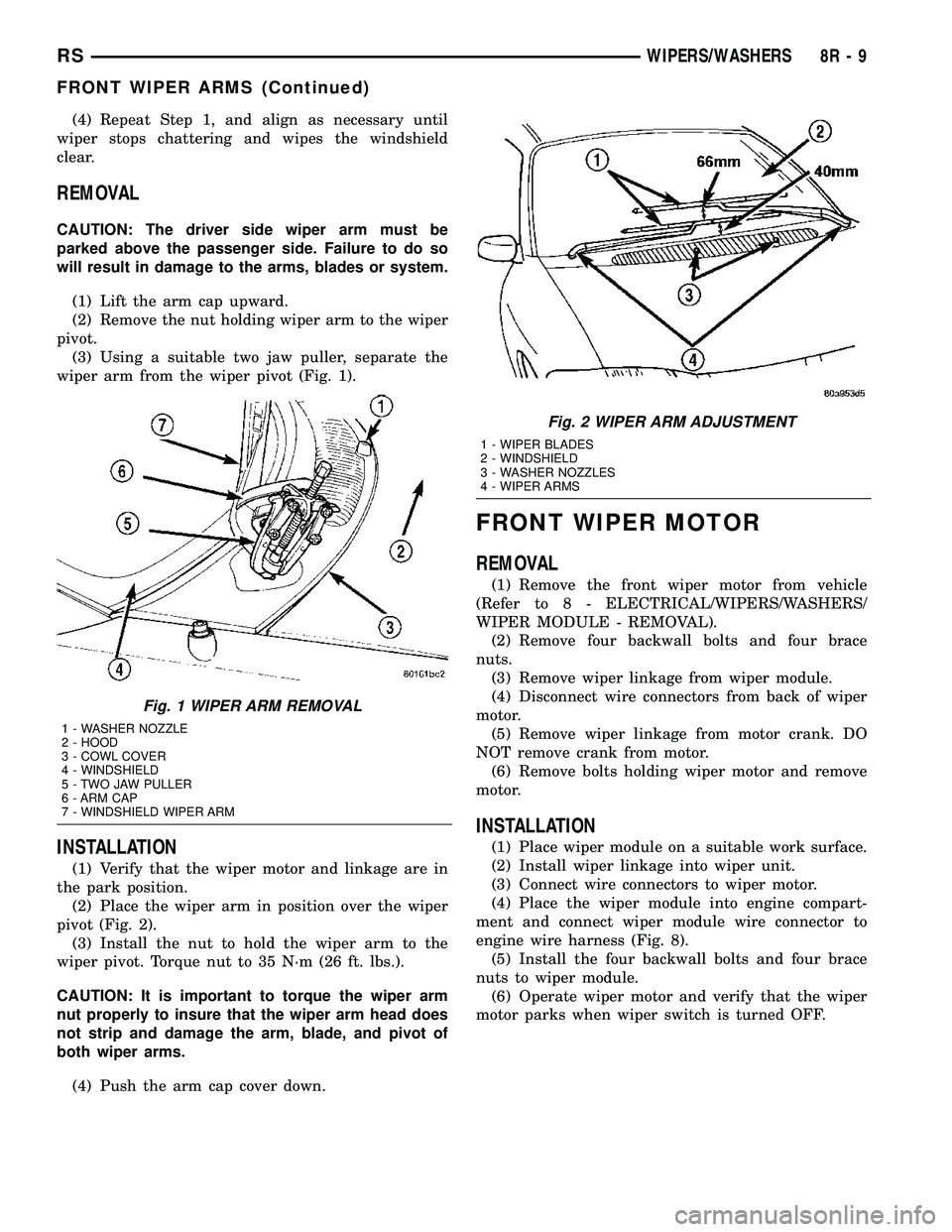
(1) Lift the arm cap upward.
(2) Remove the nut holding wiper arm to the wiper
pivot.
(3) Using a suitable two jaw puller, separate the
wiper arm from the wiper pivot (Fig. 1).
INSTALLATION
(1) Verify that the wiper motor and linkage are in
the park position.
(2) Place the wiper arm in position over the wiper
pivot (Fig. 2).
(3) Install the nut to hold the wiper arm to the
wiper pivot. Torque nut to 35 N´m (26 ft. lbs.).
CAUTION: It is important to torque the wiper arm
nut properly to insure that the wiper arm head does
not strip and damage the arm, blade, and pivot of
both wiper arms.
(4) Push the arm cap cover down.
FRONT WIPER MOTOR
REMOVAL
(1) Remove the front wiper motor from vehicle
(Refer to 8 - ELECTRICAL/WIPERS/WASHERS/
WIPER MODULE - REMOVAL).
(2) Remove four backwall bolts and four brace
nuts.
(3) Remove wiper linkage from wiper module.
(4) Disconnect wire connectors from back of wiper
motor.
(5) Remove wiper linkage from motor crank. DO
NOT remove crank from motor.
(6) Remove bolts holding wiper motor and remove
motor.
INSTALLATION
(1) Place wiper module on a suitable work surface.
(2) Install wiper linkage into wiper unit.
(3) Connect wire connectors to wiper motor.
(4) Place the wiper module into engine compart-
ment and connect wiper module wire connector to
engine wire harness (Fig. 8).
(5) Install the four backwall bolts and four brace
nuts to wiper module.
(6) Operate wiper motor and verify that the wiper
motor parks when wiper switch is turned OFF.
Fig. 1 WIPER ARM REMOVAL
1 - WASHER NOZZLE
2 - HOOD
3 - COWL COVER
4 - WINDSHIELD
5 - TWO JAW PULLER
6 - ARM CAP
7 - WINDSHIELD WIPER ARM
Fig. 2 WIPER ARM ADJUSTMENT
1 - WIPER BLADES
2 - WINDSHIELD
3 - WASHER NOZZLES
4 - WIPER ARMS
RSWIPERS/WASHERS8R-9
FRONT WIPER ARMS (Continued)
Page 697 of 2585

REAR WASHER PUMP MOTOR
REMOVAL
(1) Disconnect and isolate the battery negative
cable.
(2) Remove the engine fresh air housing inside the
engine compartment (Refer to 9 - ENGINE/AIR
INTAKE SYSTEM/AIR CLEANER HOUSING -
REMOVAL).
(3) Disconnect the washer hose at the in-line con-
nector forward of the cowl grille so that the in-line
connector remains with the washer hose from the
fresh air plenum.
(4) Disconnect the washer hose from the hose clip
located on the front fender side shield.
(5) Remove the filler tube screw.
(6) Hoist and support vehicle on hoist or jack
stands.
(7) Remove the right front wheel and tire assembly
(Refer to 22 - TIRES/WHEELS - REMOVAL).
(8) Disconnect the left right front wheelhouse
splash shield and move aside (Refer to 23 - BODY/
EXTERIOR/WHEELHOUSE SPLASH SHIELD -
REMOVAL).
(9) Drain washer fluid from the reservoir and into
a suitable clean container. This can be done by dis-
connecting the windshield washer hose from the
front (outboard) washer pump and allowing the
washer fluid to drain into a container through a tem-
porary jumper hose connected to the front washer
pump.
(10) Disconnect the electrical body harness connec-
tors to the washer pump motors and the fluid level
sensor. Slide the red lock on the connector to the
release position, then, depress the black tab and pull
the connector off the pump or sensor.
(11) Remove the two reservoir mounting screws.
(12) Disconnect the reservoir from the body mount
by raising the reservoir upward slightly and then
down so that the reservoir filler neck and front
washer hose pull through the opening in the front
fender side shield.
(13) Remove pump from reservoir by pulling pump
upper retention tab away from reservoir cavity and
then lifting pump up from mounting grommet. Do
not damage reservoir/pump sealing surface or punc-
ture reservoir during removal.
(14) Remove pump grommet and discard.
INSTALLATION
(1) Use new grommet when installing a new pump
assembly.
(2) Assure pump upper retention tab is pressed
into reservoir slot and that pump is rotated flat
against the reservoir and that pump connector is fac-
ing up in the fully seated position. Assure the pump
is aligned to and fully seated in the reservoir cavity.
(3) Push filler neck and front washer hose through
the opening in the front fender side shield. Connect
the reservoir to the body mount by lowering the res-
ervoir down.
(4) Install the two reservoir mounting screws.
Torque screws to 8.5 - 11.3 N´m (75 - 100 in. lbs.).
(5) Connect the electrical body harness connectors
to the washer pump motors and the fluid level sen-
sor. Slide the red lock on the connector to the closed
or locked position.
(6) Assure that washer hose is properly routed to
prevent pinching and possible inoperative washers.
(7) Connect the left right front wheelhouse splash
shield and move aside (Refer to 23 - BODY/EXTERI-
OR/WHEELHOUSE SPLASH SHIELD - INSTALLA-
TION).
(8) Install the right front wheel and tire assembly
(Refer to 22 - TIRES/WHEELS - INSTALLATION).
(9) lower vehicle from hoist or jack stands.
(10) Install the filler tube screw. Torque screw to
8.5 - 11.3 N´m (75 - 100 in. lbs.).
(11) Connect the washer hose to the hose clip
located on the front fender side shield.
(12) Connect the washer hose at the in-line con-
nector forward of the cowl grille.
(13) Install the engine fresh air housing inside the
engine compartment (Refer to 9 - ENGINE/AIR
INTAKE SYSTEM/AIR CLEANER HOUSING -
INSTALLATION).
(14) Connect the battery negative cable.
(15) Verify system operation.
REAR WIPER ARM
REMOVAL
(1) Remove arm nut cap.
(2) Remove wiper arm nut.
(3) Pull wiper from pivot by rocking back and
forth.
INSTALLATION
(1) Verify that wipers are in parked position.
(2) Position arm on pivot.
(3) Install wiper arm nut and torque to 20 N´m
(175 in. lbs.).
8R - 10 WIPERS/WASHERSRS
Page 699 of 2585

When rear washer is requested by depressing and
holding down the switch, the BCM then provides a
ground for the rear washer motor. Until the switch is
released, the motor will be in a continuous wipe
mode, then return to an intermittent wipe mode.
WASHER FLUID LEVEL
SWITCH
REMOVAL
(1) Disconnect and isolate the battery negative
cable.
(2) Remove the engine fresh air housing inside the
engine compartment (Refer to 9 - ENGINE/AIR
INTAKE SYSTEM/AIR CLEANER HOUSING -
REMOVAL).
(3) Disconnect the washer hose at the in-line con-
nector forward of the cowl grille so that the in-line
connector remains with the washer hose from the
fresh air plenum.
(4) Disconnect the washer hose from the hose clip
located on the front fender side shield.
(5) Remove the filler tube screw.
(6) Hoist and support vehicle on hoist or jack
stands.
(7) Remove the right front wheel and tire assembly
(Refer to 22 - TIRES/WHEELS - REMOVAL).
(8) Disconnect the left right front wheelhouse
splash shield and move aside (Refer to 23 - BODY/
EXTERIOR/WHEELHOUSE SPLASH SHIELD -
REMOVAL).
(9) Drain washer fluid from the reservoir and into
a suitable clean container. This can be done by dis-
connecting the windshield washer hose from the
front (outboard) washer pump and allowing thewasher fluid to drain into a container through a tem-
porary jumper hose connected to the front washer
pump.
(10) Disconnect the electrical body harness connec-
tors to the washer pump motors and the fluid level
sensor. Slide the red lock on the connector to the
release position, then, depress the black tab and pull
the connector off the pump or sensor.
(11) Remove the two reservoir mounting screws.
(12) Disconnect the reservoir from the body mount
by raising the reservoir upward slightly and then
down so that the reservoir filler neck and front
washer hose pull through the opening in the front
fender side shield.
(13) Remove the sensor from reservoir by using a
side foot to gently pry the sensor from the body of
the reservoir. Do not damage the reservoir/sensor
sealing surface or puncture reservoir during removal.
CAUTION: To avoid damage to the sensor, assure
the reservoir is in an upright position before remov-
ing the sensor from the reservoir. Do not rotate the
sensor during removal.
INSTALLATION
(1) Use a new grommet when installing a new sen-
sor assembly.
(2) Assure that the flat of the sensor is aligned
under the ridge of the reservoir and that the sensor
connector is facing down in the fully seated position.
This will allow for proper operation of the sensor
float switch.
(3) Push filler neck and front washer hose through
the opening in the front fender side shield. Connect
the reservoir to the body mount by lowering the res-
ervoir down.
(4) Install the two reservoir mounting screws.
Torque screws to 8.5 - 11.3 N´m (75 - 100 in. lbs.).
(5) Connect the electrical body harness connectors
to the washer pump motors and the fluid level sen-
sor. Slide the red lock on the connector to the closed
or locked position.
(6) Assure that washer hose is properly routed to
prevent pinching and possible inoperative washers.
(7) Connect the left right front wheelhouse splash
shield and move aside (Refer to 23 - BODY/EXTERI-
OR/WHEELHOUSE SPLASH SHIELD - INSTALLA-
TION).
(8) Install the right front wheel and tire assembly
(Refer to 22 - TIRES/WHEELS - INSTALLATION).
(9) lower vehicle from hoist or jack stands.
(10) Install the filler tube screw. Torque screw to
8.5 - 11.3 N´m (75 - 100 in. lbs.).
(11) Connect the washer hose to the hose clip
located on the front fender side shield.
Fig. 5 REAR WIPER/WASHER SWITCH LOCATION
1 - REAR WIPER/WASHER SWITCH
2 - HVAC CONTROL UNIT
8R - 12 WIPERS/WASHERSRS
REAR WIPER/WASHER SWITCH (Continued)
Page 700 of 2585

(12) Connect the washer hose at the in-line con-
nector forward of the cowl grille.
(13) Install the engine fresh air housing inside the
engine compartment (Refer to 9 - ENGINE/AIR
INTAKE SYSTEM/AIR CLEANER HOUSING -
INSTALLATION).
(14) Connect the battery negative cable.
(15) Verify system operation.
WASHER HOSES
REMOVAL
(1) Remove washer reservoir from vehicle (Refer to
8 - ELECTRICAL/WIPERS/WASHERS/WASHER
RESERVOIR - REMOVAL).
(2) Disconnect washer hose front the reservoir cav-
ity.
(3) Disconnect the washer hose from the reservoir
pump.
(4) Remove parts as necessary to replace washer
hose (engine compartment, interior components, etc.).
INSTALLATION
(1) Install parts as necessary to after replacing
washer hose (engine compartment, interior compo-
nents, etc.).
(2) Connect the washer hose to the reservoir
pump.
(3) Connect washer hose to the reservoir cavity.
(4) Install the washer reservoir into vehicle (Refer
to 8 - ELECTRICAL/WIPERS/WASHERS/WASHER
RESERVOIR - INSTALLATION).
WASHER RESERVOIR
REMOVAL
(1) Disconnect and isolate the battery negative
cable.
(2) Remove the engine fresh air housing inside the
engine compartment (Refer to 9 - ENGINE/AIR
INTAKE SYSTEM/AIR CLEANER HOUSING -
REMOVAL).
(3) Disconnect the washer hose at the in-line con-
nector forward of the cowl grille so that the in-line
connector remains with the washer hose from the
fresh air plenum.
(4) Disconnect the washer hose from the hose clip
located on the front fender side shield.
(5) Remove the filler tube screw.
(6) Hoist and support vehicle on hoist or jack
stands.
(7) Remove the right front wheel and tire assembly
(Refer to 22 - TIRES/WHEELS - REMOVAL).(8) Disconnect the left right front wheelhouse
splash shield and move aside (Refer to 23 - BODY/
EXTERIOR/WHEELHOUSE SPLASH SHIELD -
REMOVAL).
(9) Drain washer fluid from the reservoir and into
a suitable clean container. This can be done by dis-
connecting the windshield washer hose from the
front (outboard) washer pump and allowing the
washer fluid to drain into a container through a tem-
porary jumper hose connected to the front washer
pump.
(10) Disconnect the electrical body harness connec-
tors to the washer pump motors and the fluid level
sensor. Slide the red lock on the connector to the
release position, then, depress the black tab and pull
the connector off the pump or sensor.
(11) Remove the two reservoir mounting screws.
(12) Disconnect the reservoir from the body mount
by raising the reservoir upward slightly and then
down so that the reservoir filler neck and front
washer hose pull through the opening in the front
fender side shield.
INSTALLATION
(1) Push filler neck and front washer hose through
the opening in the front fender side shield. Connect
the reservoir to the body mount by lowering the res-
ervoir down.
(2) Install the two reservoir mounting screws.
Torque screws to 8.5 - 11.3 N´m (75 - 100 in. lbs.).
(3) Connect the electrical body harness connectors
to the washer pump motors and the fluid level sen-
sor. Slide the red lock on the connector to the closed
or locked position.
(4) Assure that washer is properly routed to pre-
vent pinching and possible inoperative washers.
(5) Connect the left right front wheelhouse splash
shield and move aside (Refer to 23 - BODY/EXTERI-
OR/WHEELHOUSE SPLASH SHIELD - INSTALLA-
TION).
(6) Install the right front wheel and tire assembly
(Refer to 22 - TIRES/WHEELS - INSTALLATION).
(7) lower vehicle from hoist or jack stands.
(8) Install the filler tube screw. Torque screw to 8.5
- 11.3 N´m (75 - 100 in. lbs.).
(9) Connect the washer hose to the hose clip
located on the front fender side shield.
(10) Connect the washer hose at the in-line con-
nector forward of the cowl grille.
(11) Install the engine fresh air housing inside the
engine compartment (Refer to 9 - ENGINE/AIR
INTAKE SYSTEM/AIR CLEANER HOUSING -
INSTALLATION).
(12) Connect the battery negative cable.
(13) Verify system operation.
RSWIPERS/WASHERS8R-13
WASHER FLUID LEVEL SWITCH (Continued)
Page 701 of 2585
WIPER BLADES
REMOVAL
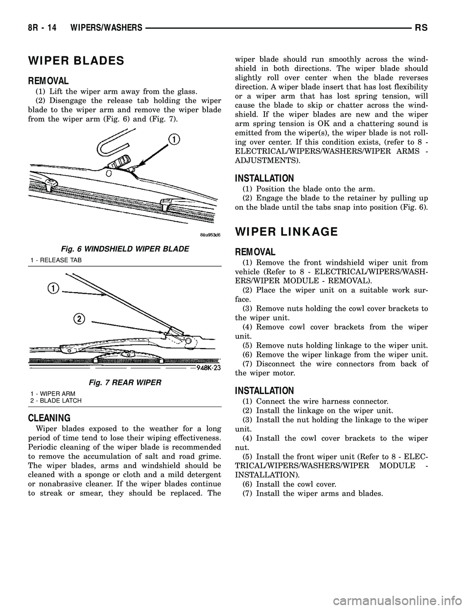
(1) Lift the wiper arm away from the glass.
(2) Disengage the release tab holding the wiper
blade to the wiper arm and remove the wiper blade
from the wiper arm (Fig. 6) and (Fig. 7).
CLEANING
Wiper blades exposed to the weather for a long
period of time tend to lose their wiping effectiveness.
Periodic cleaning of the wiper blade is recommended
to remove the accumulation of salt and road grime.
The wiper blades, arms and windshield should be
cleaned with a sponge or cloth and a mild detergent
or nonabrasive cleaner. If the wiper blades continue
to streak or smear, they should be replaced. Thewiper blade should run smoothly across the wind-
shield in both directions. The wiper blade should
slightly roll over center when the blade reverses
direction. A wiper blade insert that has lost flexibility
or a wiper arm that has lost spring tension, will
cause the blade to skip or chatter across the wind-
shield. If the wiper blades are new and the wiper
arm spring tension is OK and a chattering sound is
emitted from the wiper(s), the wiper blade is not roll-
ing over center. If this condition exists, (refer to 8 -
ELECTRICAL/WIPERS/WASHERS/WIPER ARMS -
ADJUSTMENTS).
INSTALLATION
(1) Position the blade onto the arm.
(2) Engage the blade to the retainer by pulling up
on the blade until the tabs snap into position (Fig. 6).
WIPER LINKAGE
REMOVAL
(1) Remove the front windshield wiper unit from
vehicle (Refer to 8 - ELECTRICAL/WIPERS/WASH-
ERS/WIPER MODULE - REMOVAL).
(2) Place the wiper unit on a suitable work sur-
face.
(3) Remove nuts holding the cowl cover brackets to
the wiper unit.
(4) Remove cowl cover brackets from the wiper
unit.
(5) Remove nuts holding linkage to the wiper unit.
(6) Remove the wiper linkage from the wiper unit.
(7) Disconnect the wire connectors from back of
the wiper motor.
INSTALLATION
(1) Connect the wire harness connector.
(2) Install the linkage on the wiper unit.
(3) Install the nut holding the linkage to the wiper
unit.
(4) Install the cowl cover brackets to the wiper
nut.
(5) Install the front wiper unit (Refer to 8 - ELEC-
TRICAL/WIPERS/WASHERS/WIPER MODULE -
INSTALLATION).
(6) Install the cowl cover.
(7) Install the wiper arms and blades.
Fig. 6 WINDSHIELD WIPER BLADE
1 - RELEASE TAB
Fig. 7 REAR WIPER
1 - WIPER ARM
2 - BLADE LATCH
8R - 14 WIPERS/WASHERSRS
Page 702 of 2585
WIPER MODULE
REMOVAL
(1) Release the hood latch and open hood.
(2) Disconnect and isolate the battery negative
cable.
(3) Remove the wiper arms.
(4) Remove the cowl cover (Refer to 23 - BODY/
EXTERIOR/COWL GRILLE - REMOVAL).
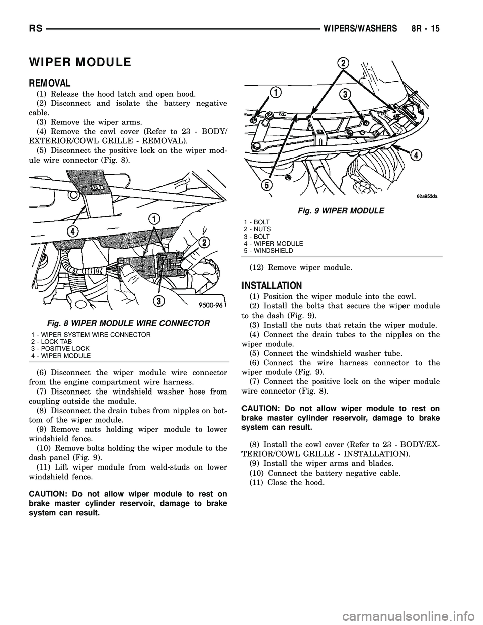
(5) Disconnect the positive lock on the wiper mod-
ule wire connector (Fig. 8).
(6) Disconnect the wiper module wire connector
from the engine compartment wire harness.
(7) Disconnect the windshield washer hose from
coupling outside the module.
(8) Disconnect the drain tubes from nipples on bot-
tom of the wiper module.
(9) Remove nuts holding wiper module to lower
windshield fence.
(10) Remove bolts holding the wiper module to the
dash panel (Fig. 9).
(11) Lift wiper module from weld-studs on lower
windshield fence.
CAUTION: Do not allow wiper module to rest on
brake master cylinder reservoir, damage to brake
system can result.(12) Remove wiper module.
INSTALLATION
(1) Position the wiper module into the cowl.
(2) Install the bolts that secure the wiper module
to the dash (Fig. 9).
(3) Install the nuts that retain the wiper module.
(4) Connect the drain tubes to the nipples on the
wiper module.
(5) Connect the windshield washer tube.
(6) Connect the wire harness connector to the
wiper module (Fig. 9).
(7) Connect the positive lock on the wiper module
wire connector (Fig. 8).
CAUTION: Do not allow wiper module to rest on
brake master cylinder reservoir, damage to brake
system can result.
(8) Install the cowl cover (Refer to 23 - BODY/EX-
TERIOR/COWL GRILLE - INSTALLATION).
(9) Install the wiper arms and blades.
(10) Connect the battery negative cable.
(11) Close the hood.
Fig. 8 WIPER MODULE WIRE CONNECTOR
1 - WIPER SYSTEM WIRE CONNECTOR
2 - LOCK TAB
3 - POSITIVE LOCK
4 - WIPER MODULE
Fig. 9 WIPER MODULE
1 - BOLT
2 - NUTS
3 - BOLT
4 - WIPER MODULE
5 - WINDSHIELD
RSWIPERS/WASHERS8R-15
Page 2162 of 2585
INSTALLATION
(1) Reverse removal procedure.
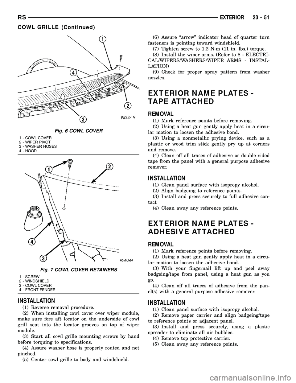
(2) When installing cowl cover over wiper module,
make sure fore aft locator on the underside of cowl
grill seat into the locator grooves on top of wiper
module.
(3) Start all cowl grille mounting screws by hand
before torquing to specifications.
(4) Assure washer hose is properly routed and not
pinched.
(5) Center cowl grille to body and windshield.(6) Assure ªarrowº indicator head of quarter turn
fasteners is pointing toward windshield.
(7) Tighten screw to 1.2 N´m (11 in. lbs.) torque.
(8) Install the wiper arms. (Refer to 8 - ELECTRI-
CAL/WIPERS/WASHERS/WIPER ARMS - INSTAL-
LATION)
(9) Check for proper spray pattern from washer
nozzles.
EXTERIOR NAME PLATES -
TAPE ATTACHED
REMOVAL
(1) Mark reference points before removing.
(2) Using a heat gun gently apply heat in a circu-
lar motion to loosen the adhesive bond.
(3) Using a nonmetallic prying device, such as a
plastic or wood trim stick gently pry up at corners
and remove.
(4) Clean off all traces of adhesive or double sided
tape from the panel with a general purpose adhesive
remover.
INSTALLATION
(1) Clean panel surface with isopropy alcohol.
(2) Align badgeing to reference points.
(3) Install and press securely to full adhesive con-
tact
(4) Clean away any reference points.
EXTERIOR NAME PLATES -
ADHESIVE ATTACHED
REMOVAL
(1) Mark reference points before removing.
(2) Using a heat gun gently apply heat in a circu-
lar motion to loosen the adhesive bond.
(3) With your fingernail lift up and peel away
badgeing/tape from panel, using a heat gun as you
go.
(4) Clean off all traces of adhesive from the pan-
el(s) with a general purpose adhesive remover.
INSTALLATION
(1) Clean panel surface with isopropy alcohol.
(2) Remove paper carrier and align badgeing/tape
to reference points or adjacent panel.
(3) Install and press securely, using a plastic
spreader to eliminate all air bubbles.
(4) Remove top protective carrier.
(5) Clean away any reference points.
Fig. 6 COWL COVER
1 - COWL COVER
2 - WIPER PIVOT
3 - WASHER HOSES
4 - HOOD
Fig. 7 COWL COVER RETAINERS
1 - SCREW
2 - WINDSHIELD
3 - COWL COVER
4 - FRONT FENDER
RSEXTERIOR23-51
COWL GRILLE (Continued)
Page 2221 of 2585
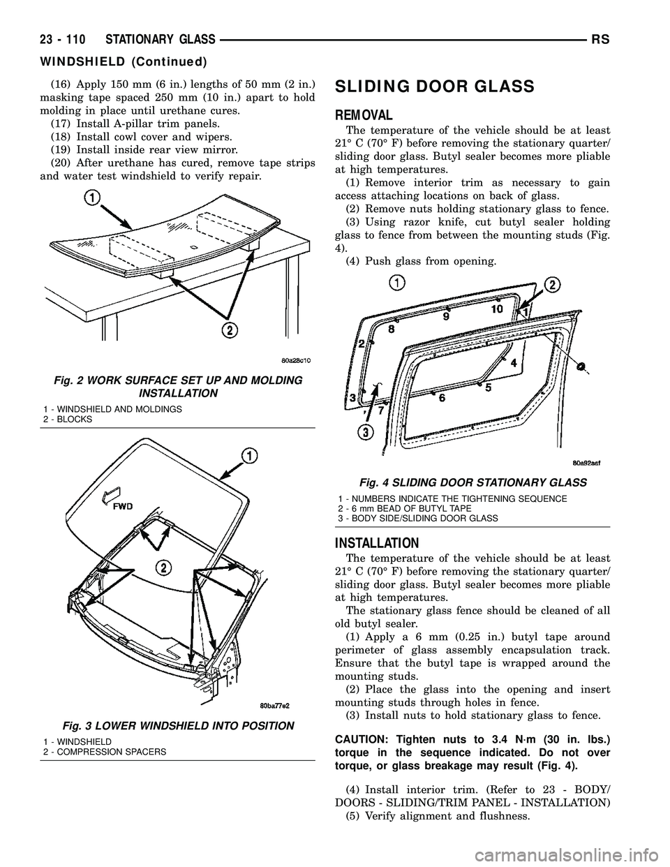
(16) Apply 150 mm (6 in.) lengths of 50 mm (2 in.)
masking tape spaced 250 mm (10 in.) apart to hold
molding in place until urethane cures.
(17) Install A-pillar trim panels.
(18) Install cowl cover and wipers.
(19) Install inside rear view mirror.
(20) After urethane has cured, remove tape strips
and water test windshield to verify repair.SLIDING DOOR GLASS
REMOVAL
The temperature of the vehicle should be at least
21É C (70É F) before removing the stationary quarter/
sliding door glass. Butyl sealer becomes more pliable
at high temperatures.
(1) Remove interior trim as necessary to gain
access attaching locations on back of glass.
(2) Remove nuts holding stationary glass to fence.
(3) Using razor knife, cut butyl sealer holding
glass to fence from between the mounting studs (Fig.
4).
(4) Push glass from opening.
INSTALLATION
The temperature of the vehicle should be at least
21É C (70É F) before removing the stationary quarter/
sliding door glass. Butyl sealer becomes more pliable
at high temperatures.
The stationary glass fence should be cleaned of all
old butyl sealer.
(1) Applya6mm(0.25 in.) butyl tape around
perimeter of glass assembly encapsulation track.
Ensure that the butyl tape is wrapped around the
mounting studs.
(2) Place the glass into the opening and insert
mounting studs through holes in fence.
(3) Install nuts to hold stationary glass to fence.
CAUTION: Tighten nuts to 3.4 N´m (30 in. lbs.)
torque in the sequence indicated. Do not over
torque, or glass breakage may result (Fig. 4).
(4) Install interior trim. (Refer to 23 - BODY/
DOORS - SLIDING/TRIM PANEL - INSTALLATION)
(5) Verify alignment and flushness.
Fig. 2 WORK SURFACE SET UP AND MOLDING
INSTALLATION
1 - WINDSHIELD AND MOLDINGS
2 - BLOCKS
Fig. 3 LOWER WINDSHIELD INTO POSITION
1 - WINDSHIELD
2 - COMPRESSION SPACERS
Fig. 4 SLIDING DOOR STATIONARY GLASS
1 - NUMBERS INDICATE THE TIGHTENING SEQUENCE
2-6mmBEAD OF BUTYL TAPE
3 - BODY SIDE/SLIDING DOOR GLASS
23 - 110 STATIONARY GLASSRS
WINDSHIELD (Continued)
Page 2423 of 2585

inserted in a small well in the body of the expansion
valve that is filled with a special silicone-based ther-
mal grease. A small molded plastic push-in retainer
secures the sensor to a threaded hole in the top sur-
face of the expansion valve. Two terminals within a
molded plastic connector receptacle on the sensor
connect it to the vehicle electrical system through a
take out and connector of the HVAC wire harness.
The evaporator temperature sensor cannot be
adjusted or repaired and, if faulty or damaged, it
must be replaced.
OPERATION
The evaporator temperature sensor monitors the
temperature of the A/C evaporator. The sensor will
change its internal resistance in response to the tem-
peratures it monitors. The A/C-heater control is con-
nected to the sensor through a sensor ground circuit
and a sensor signal circuit. As the evaporator tem-
perature increases, the resistance of the sensor
decreases and the voltage monitored by the control
decreases. The control uses this monitored voltage
reading to an indication of the evaporator tempera-
ture. The A/C-heater control is programmed to
respond to this input by sending electronic messages
to the powertrain control module (PCM) over the pro-
grammable communications interface (PCI) data bus,
and the PCM then cycles the A/C compressor clutch
as necessary to optimize A/C system performance andto protect the system from evaporator freezing. The
external location of the sensor allows the sensor to be
removed or installed without disturbing the refriger-
ant in the system. The evaporator temperature sen-
sor is diagnosed using a DRBIIItscan tool. Refer to
Body Diagnostic Procedures.
REMOVAL
REMOVAL - AUTOMATIC TEMPERATURE
CONTROL (ATC)
(1) Disconnect and isolate the battery negative
cable.
(2) Remove the air cleaner housing from the right
side of the engine compartment.
(3) Remove the windshield wiper assembly from
the vehicle (Refer to 8 - ELECTRICAL/WIPERS/
WASHERS/WIPER MODULE - REMOVAL).
(4) Remove the temperature sensor retainer from
the expansion valve (Fig. 17).
(5) Pull the evaporator temperature sensor away
from the expansion valve far enough to access the
red release ring on the wiring connector. Push the
red ring toward the connector to release the lock and
disconnect the wire harness connector from the tem-
perature sensor.
(6) Remove the evaporator temperature sensor
from the engine compartment.
Fig. 16 Evaporator Temperature Sensor - ATC
System
1 - EVAPORATOR TEMPERATURE SENSOR
2 - A/C EXPANSION VALVE
Fig. 17 Evaporator Temperature Sensor - ATC
System
1 - RIGHT FRONT STRUT TOWER
2 - EVAPORATOR TEMPERATURE SENSOR
3 - EXPANSION VALVE
4 - DASH PANEL
5 - RETAINER
24 - 28 CONTROLS - FRONTRS
EVAPORATOR TEMPERATURE SENSOR (Continued)
Page 2446 of 2585

(3) Align the locator hole on the center floor distri-
bution duct with the weld stud on the front floor
panel.
(4) Using hand pressure, push the locator hole of
the center floor distribution duct down over the weld
stud on the front floor panel.
(5) Reinstall the carpet onto the front floor panel
and under the instrument panel (Refer to 23 - BODY/
INTERIOR/CARPETS AND FLOOR MATS -
INSTALLATION).
HVAC HOUSING
REMOVAL
REMOVAL
WARNING: REFER TO THE APPLICABLE WARN-
INGS AND CAUTIONS FOR THIS SYSTEM BEFORE
PERFORMING THE FOLLOWING OPERATION (Refer
to 24 - HEATING & AIR CONDITIONING/PLUMBING -
WARNING) AND (Refer to 24 - HEATING & AIR CON-
DITIONING/PLUMBING - CAUTION).
WARNING: ON VEHICLES EQUIPPED WITH AIR-
BAGS, DISABLE THE AIRBAG SYSTEM BEFORE
ATTEMPTING ANY STEERING WHEEL, STEERING
COLUMN, OR INSTRUMENT PANEL COMPONENT
DIAGNOSIS OR SERVICE. DISCONNECT AND ISO-
LATE THE BATTERY NEGATIVE (GROUND) CABLE,
THEN WAIT TWO MINUTES FOR THE AIRBAG SYS-
TEM CAPACITOR TO DISCHARGE BEFORE PER-FORMING FURTHER DIAGNOSIS OR SERVICE. THIS
IS THE ONLY SURE WAY TO DISABLE THE AIRBAG
SYSTEM. FAILURE TO TAKE THE PROPER PRE-
CAUTIONS COULD RESULT IN ACCIDENTAL AIR-
BAG DEPLOYMENT AND POSSIBLE PERSONAL
INJURY.
(1) Recover the refrigerant from the refrigerant
system (Refer to 24 - HEATING & AIR CONDITION-
ING/PLUMBING - FRONT/REFRIGERANT - STAN-
DARD PROCEDURE - REFRIGERANT
RECOVERY).
(2) Drain the engine cooling system (Refer to 7 -
COOLING - STANDARD PROCEDURE - COOLING
SYSTEM DRAIN).
(3) Disconnect and isolate the negative battery
cable.
(4) Remove the windshield wiper module from the
vehicle (Refer to 8 - ELECTRICAL/WIPERS/WASH-
ERS/WIPER MODULE - REMOVAL).
(5) Disconnect the liquid line and suction line from
the expansion valve (Refer to 24 - HEATING & AIR
CONDITIONING/PLUMBING - FRONT/LIQUID
LINE - REMOVAL) and (Refer to 24 - HEATING &
AIR CONDITIONING/PLUMBING - FRONT/SUC-
TION LINE - REMOVAL).
(6) Disconnect the heater hoses from the heater
core tubes (Refer to 24 - HEATING & AIR CONDI-
TIONING/PLUMBING - FRONT/HEATER HOSE -
REMOVAL).
(7) On LHD models, remove the one bolt that
secures the HVAC housing to the dash panel (Fig.
12).
(8) Remove the three nuts that secure the HVAC
housing to the dash panel.
(9) Remove the instrument panel from the passen-
ger compartment (Refer to 23 - BODY/INSTRU-
MENT PANEL/INSTRUMENT PANEL ASSEMBLY -
REMOVAL).
(10) Remove the floor distribution duct (Refer to
24 - HEATING & AIR CONDITIONING/DISTRIBU-
TION - FRONT/FLOOR DISTRIBUTION DUCTS -
REMOVAL).
(11) Remove the bolt or bolts (depending on appli-
cation) that secure the HVAC housing to the passen-
ger compartment side of the dash panel (Fig. 13) or
(Fig. 14).
(12) Pull the HVAC housing rearward far enough
for the mounting studs to clear the dash panel and
remove the housing from the passenger compart-
ment.
DISSASEMBLY
(1) Remove the HVAC housing from the vehicle
and place it on a workbench (Refer to 24 - HEATING
& AIR CONDITIONING/DISTRIBUTION - FRONT/
HVAC HOUSING - REMOVAL).
Fig. 11 Floor Distribution Ducts - LHD Shown, RHD
Typical
1 - CENTER FLOOR DISTRIBUTION DUCT
2 - RIGHT FLOOR DISTRIBUTION DUCT
3 - LEFT FLOOR DISTRIBUTION DUCT
4 - WELD STUD
RSDISTRIBUTION - FRONT24-51
FLOOR DISTRIBUTION DUCTS (Continued)