8e electrical CHRYSLER VOYAGER 2004 Service Manual
[x] Cancel search | Manufacturer: CHRYSLER, Model Year: 2004, Model line: VOYAGER, Model: CHRYSLER VOYAGER 2004Pages: 2585, PDF Size: 62.54 MB
Page 667 of 2585
the seat back trim cover will tear open and allow the
side airbag to fully inflate and quickly deflate.
SEAT BELT BUCKLE - FRONT
INBOARD
REMOVAL
The seat belt tensioners are integral to the front
seat belt buckles. They are not serviceable and must
be replaced after a frontal impact event. The entire
front seat belt buckle assembly must be replaced as
an assembly.
(1) Disconnect and isolate the battery negative
cable.
(2) Wait two minutes for the system reserve capac-
itor to discharge before beginning any airbag compo-
nent service procedure.
(3) Remove screws attaching front inboard side
cover to seat cushion frame.
(4) Remove side cover from vehicle.
(5) Disconnect the tensioner wire connector from
seat belt buckle.
(6) Remove bolt attaching seat belt buckle to front
seat track.
(7) Remove buckle from vehicle.
INSTALLATION
The seat belt tensioners are integral to the front
seat belt buckles. They are not serviceable and must
be replaced after a frontal impact event. The entire
front seat belt buckle assembly must be replaced as
an assembly.
(1) Place buckle into position.
(2) Install bolt attaching seat belt buckle to front
seat track. Torque bolt to 39 N´m (29 ft. lbs.).
(3) Connect the seat belt tensioner electrical con-
nector.
(4) Install side cover into position.
(5) Install screws attaching front inboard side
cover to seat cushion frame.
WARNING: DO NOT CONNECT THE BATTERY NEG-
ATIVE CABLE (Refer to 8 - ELECTRICAL/RE-
STRAINTS - DIAGNOSIS AND TESTING).
PERSONAL INJURY OR DEATH MAY RESULT IF
THE SYSTEM TEST IS NOT PERFORMED PROP-
ERLY.
SEAT BELT BUCKLE - FIRST
ROW INBOARD - QUAD
BUCKET
REMOVAL
(1) Remove seat from vehicle.
(2) Remove screws attaching inboard side cover to
seat cushion.
(3) Remove side cover from seat.
(4) Remove bolts attaching recliner bracket to seat
cushion.
(5) Remove recliner bracket from seat.
(6) Remove bolt attaching seat belt buckle to seat
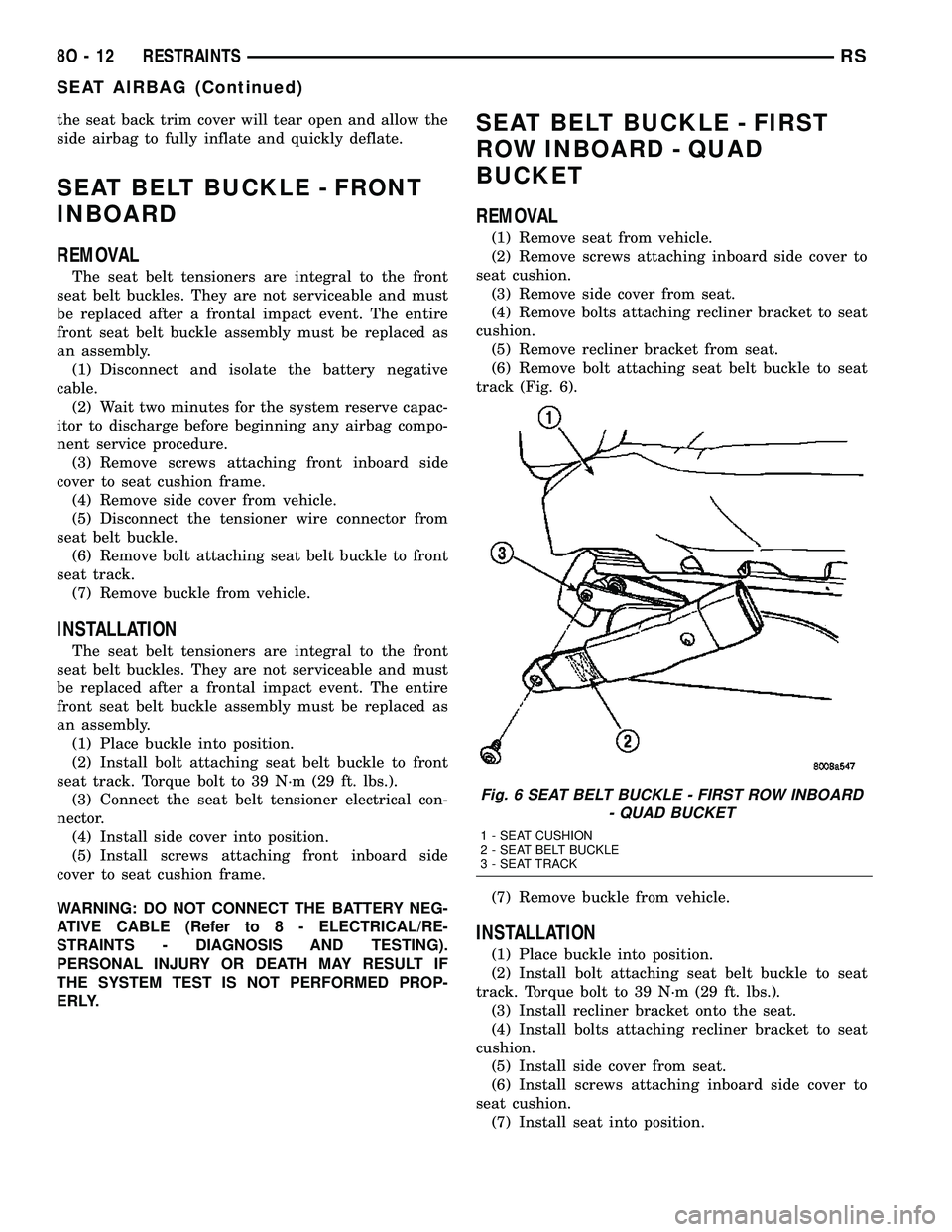
track (Fig. 6).
(7) Remove buckle from vehicle.
INSTALLATION
(1) Place buckle into position.
(2) Install bolt attaching seat belt buckle to seat
track. Torque bolt to 39 N´m (29 ft. lbs.).
(3) Install recliner bracket onto the seat.
(4) Install bolts attaching recliner bracket to seat
cushion.
(5) Install side cover from seat.
(6) Install screws attaching inboard side cover to
seat cushion.
(7) Install seat into position.
Fig. 6 SEAT BELT BUCKLE - FIRST ROW INBOARD
- QUAD BUCKET
1 - SEAT CUSHION
2 - SEAT BELT BUCKLE
3 - SEAT TRACK
8O - 12 RESTRAINTSRS
SEAT AIRBAG (Continued)
Page 669 of 2585

(4) Install turning loop to height adjuster. Torque
anchor bolt to 39 N´m (29 ft. lbs.).
SEAT BELT HEIGHT
ADJUSTER KNOB
REMOVAL
(1) Disengage clips attaching clam shell cover to
seat belt turning loop and open cover.
(2) Using a trim tool (special tool #C-4755), gently
pry knob from seat belt height adjuster.
INSTALLATION
(1) Place seat belt height adjuster knob in position
on height adjuster.
(2) Firmly push knob on until retainers engage.
(3) Reinstall turning loop clam shell cover.
(4) Verify seat belt operation. Make sure it moves
through loop without binding.
SEAT BELT & RETRACTOR -
OUTBOARD - FRONT
REMOVAL
(1) Open door.
(2) Move seat all the way forward.
(3) Open hood.
(4) Disconnect and isolate the negative battery
cable.
(5) Remove shoulder harness height adjuster knob
by pulling it straight away from adjuster.
(6) Remove cover from seat belt turning loop.
(7) Remove bolt attaching turning loop to shoulder
belt height adjuster.
(8) Remove upper B-pillar trim cover.
(9) Remove the lower seat belt anchor bolt.
(10) Remove front door sill plate.
(11) Remove sliding door sill plate.
(12) Remove lower B-pillar trim cover.
(13) Disconnect the seat belt retractor electrical
connector.
(14) Remove seat belt retractor attaching bolt.
(15) Remove the seat belt and retractor from vehi-
cle.
INSTALLATION
Inspect the condition of the shoulder belt and lap
belt. Replace any belt that is cut, frayed, torn, or
damaged in any way. Also, replace the shoulder belt
if the retractor is either damaged or inoperative.
(1) Place seat belt and retractor into position.
(2) Install bolt attaching seat belt retractor to
B-pillar. Torque bolt to 39 N´m (29 ft. lbs.).(3) Connect the seat belt retractor electrical con-
nector.
(4) Install the lower B-pillar trim cover.
(5) Install the sliding door sill plate.
(6) Install the front door sill plate.
(7) Install the lower seat belt anchor bolt. Torque
bolt to 39 N´m (29 ft. lbs.).
(8) Install the upper B-pillar trim cover.
(9) Install the bolt attaching turning loop to shoul-
der belt height adjuster. Torque bolt to 39 N´m (29 ft.
lbs.).
(10) Install the cover to the seat belt turning loop.
(11) Install the shoulder harness height adjuster
knob by pushing it straight onto the adjuster.
(12) Connect the battery negative cable.
(13) Verify vehicle and system operation.
(14) Move seat back to approximate customer posi-
tion.
(15) Close hood and door.
SEAT BELT & RETRACTOR -
FIRST ROW - OUTBOARD
REMOVAL
(1) Remove first and second row seats.
(2) Remove first row seat belt lower anchor bolt.
(3) Remove first row seat belt upper turning loop
anchor bolt.
(4) Remove liftgate sill plate.
(5) Remove upper liftgate trim.
(6) Remove second seat lower anchor bolt.
(7) Remove second seat upper turning loop anchor
bolt.
(8) Remove D-pillar trim cover.
(9) Disconnect speaker connector. The left side has
the speaker mounted in the D-pillar trim cover and
the right side will have the speaker mounted in the
rear of the quarter trim panel, but the connector is
accessible from the rear after the D-pillar trim is
removed.
(10) Remove quarter trim bolster.
(11) Remove quarter trim panel screws.
(12) Remove quarter trim panel.
(13) Remove first row seat belt and retractor
retaining bolt.
(14) Remove first row seat belt and retractor from
vehicle.
INSTALLATION
(1) Install first row seat belt and retractor. Torque
bolt to 39 N´m (29 ft. lbs.).
(2) Install quarter trim panel.
(3) Install quarter trim panel screws.
(4) Install quarter trim bolster.
8O - 14 RESTRAINTSRS
SEAT BELT HEIGHT ADJUSTER-BORC-PILLAR (Continued)
Page 676 of 2585
AUTOMATIC SPEED CONTROL OVERSPEED
REDUCTION
DESCRIPTION
Transmission control software includes an auto-
matic speed control overspeed reduction feature. This
maintains vehicle speed at the selected set point
when descending a grade.
OPERATION
The TCM (on SBEC vehicles) (PCM on NGC vehi-
cles) first senses that the speed control is set. If the
set speed is exceeded by more than 4 mph (6.5
km/hr) and the throttle is closed, the TCM (on SBEC
vehicles) (PCM on NGC vehicles) causes the trans-
axle to downshift to THIRD gear. After downshifting,
the automatic speed control resumes normal opera-
tion. To ensure that an upshift is appropriate after
the set speed is reached, the TCM (on SBEC vehi-
cles) (PCM on NGC vehicles) waits until the speed
control system opens the throttle at least 6 degrees
before upshifting to OVERDRIVE again.
If the driver applies the brakes, canceling auto-
matic speed control operation with the transaxle still
in THIRD gear, the TCM (on SBEC vehicles) (PCM
on NGC vehicles) maintains this gear until the driver
opens the throttle at least 6 degrees to avoid an inap-
propriate upshift. The upshift is also delayed for 2.5
seconds after reaching the 6 degrees throttle opening
in anticipation that the driver might open the throt-
tle enough to require THIRD gear. This will avoid
unnecessary and disturbing transmission cycling. If
the automatic speed control RESUME feature is used
after braking, the upshift is delayed until the set
speed is achieved to reduce cycling and provide bet-
ter response.
DIAGNOSIS AND TESTING - ROAD TEST
Perform a vehicle road test to verify reports of
speed control system malfunction. The road test
should include attention to the speedometer. Speed-
ometer operation should be smooth and without flut-
ter at all speeds.
Flutter in the speedometer indicates a problem
which might cause surging in the speed control sys-
tem. The cause of any speedometer problems should
be corrected before proceeding. Refer to the Instru-
ment Cluster for speedometer diagnosis.
If a road test verifies an inoperative system, and
the speedometer operates properly, check for:
²A Diagnostic Trouble Code (DTC). If a DTC
exists, conduct tests per the Powertrain Diagnostic
Procedures manual.
²A misadjusted brake (stop) lamp switch. This
could also cause an intermittent problem.
²Loose or corroded electrical connections at the
servo. Corrosion should be removed from electrical
terminals and a light coating of Mopar Multipurpose
Grease, or equivalent, applied.
²Leaking vacuum reservoir.
²Loose or leaking vacuum hoses or connections.
²Defective one-way vacuum check valve.
²Secure attachment at both ends of the speed
control servo cable.
²Smooth operation of throttle linkage and throttle
body air valve.
²Conduct electrical test at PCM.
²Failed speed control servo. Do the servo vacuum
test.
CAUTION: When test probing for voltage or conti-
nuity at electrical connectors, care must be taken
not to damage connector, terminals or seals. If
these components are damaged, intermittent or
complete system failure may occur.
SPECIFICATIONS - TORQUE
DESCRIPTION N´m Ft. Lbs. In. Lbs.
Servo Mounting Bracket
Nuts14 10.3 123.9
Servo Mounting Bracket
Bolts14 10.3 123.9
Servo Mounting Nuts 6.7 60
RSSPEED CONTROL8P-3
SPEED CONTROL (Continued)
Page 677 of 2585
CABLE
DESCRIPTION
The speed control servo cable is connected between
the speed control vacuum servo diaphragm and the
throttle body control linkage.
OPERATION
This cable causes the throttle control linkage to
open or close the throttle valve in response to move-
ment of the vacuum servo diaphragm.
REMOVAL
(1) Disconnect the negative battery cable.
(2) Remove speed control cable from throttle cam
by sliding clasp out hole used for throttle cable.
(3) Compress the retaining tabs on the cable and
slide cable out of bracket.
(4) Disconnect electrical connectors and vacuum
hose from servo.
(5) Remove two nuts attaching speed control cable
and mounting bracket to servo.
(6) Pull cable away from servo to expose retaining
clip and remove clip attaching cable to servo.
(7) Remove speed control cable.
INSTALLATION
(1) Slide cable into throttle cable bracket and
engage retaining tabs.
(2) Rotate the throttle cam forward to the wide
open position and install speed control cable clasp.
(3) Rotate the throttle cam forward to the wide
open position and install throttle cable clasp.
(4) Install retaining clip that attaches cable to
servo.
(5) Insert servo studs through holes in the mount-
ing bracket and speed control cable.
(6) Install nuts, tighten to 6.7 N´m (60 in. lbs.).
(7) Connect vacuum hose to servo.
(8) Connect electrical connector.
(9) Install servo and bracket and tighten nuts and
bolt.
(10) Connect negative battery cable.
SERVO
DESCRIPTION
The servo unit consists of a solenoid valve body,
and a vacuum chamber. The solenoid valve body con-
tains three solenoids:
²Vacuum
²Vent
²Dump
The vacuum chamber contains a diaphragm with a
cable attached to control the throttle linkage.
OPERATION
The PCM controls the solenoid valve body. The
solenoid valve body controls the application and
release of vacuum to the diaphragm of the vacuum
servo. The servo unit cannot be repaired and is ser-
viced only as a complete assembly.
Power is supplied to the servo by the PCM through
the brake switch. The PCM controls the ground path
for the vacuum and vent solenoids.
The dump solenoid is energized anytime it receives
power. If power to the dump solenoid is interrupted,
the solenoid dumps vacuum in the servo. This pro-
vides a safety backup to the vent and vacuum sole-
noids.
The vacuum and vent solenoids must be grounded
by the PCM to operate. When the PCM grounds the
vacuum servo solenoid, the solenoid allows vacuum
to enter the servo and pull open the throttle plate
using the cable. When the PCM breaks the ground,
the solenoid closes and no more vacuum is allowed to
enter the servo. The PCM also operates the vent sole-
noid via ground. The vent solenoid opens and closes a
passage to bleed or hold vacuum in the servo as
required.
The PCM cycles the vacuum and vent solenoids to
maintain the set speed, or to accelerate and deceler-
ate the vehicle. To increase throttle opening, the
PCM grounds the vacuum and vent solenoids. To
decrease throttle opening, the PCM removes the
grounds from the vacuum and vent solenoids.
8P - 4 SPEED CONTROLRS
Page 678 of 2585
REMOVAL
(1) Release hood latch and open hood.
(2) Disconnect the negative battery cable.
(3) Disconnect the throttle and speed control cable
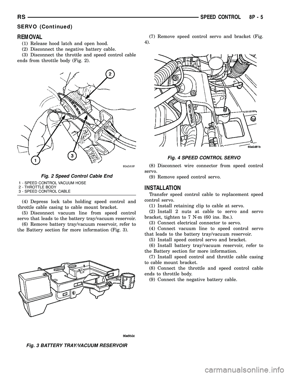
ends from throttle body (Fig. 2).
(4) Depress lock tabs holding speed control and
throttle cable casing to cable mount bracket.
(5) Disconnect vacuum line from speed control
servo that leads to the battery tray/vacuum reservoir.
(6) Remove battery tray/vacuum reservoir, refer to
the Battery section for more information (Fig. 3).(7) Remove speed control servo and bracket (Fig.
4).
(8) Disconnect wire connector from speed control
servo.
(9) Remove speed control servo.
INSTALLATION
Transfer speed control cable to replacement speed
control servo.
(1) Install retaining clip to cable at servo.
(2) Install 2 nuts at cable to servo and servo
bracket, tighten to 7 N´m (60 ins. lbs.).
(3) Connect electrical connector to servo.
(4) Connect vacuum line to speed control servo
that leads to the battery tray/vacuum reservoir.
(5) Install speed control servo and bracket.
(6) Install battery tray/vacuum reservoir, refer to
the Battery section for more information.
(7) Install speed control and throttle cable casing
to cable mount bracket.
(8) Connect the throttle and speed control cable
ends to throttle body.
(9) Connect the negative battery cable.
Fig. 2 Speed Control Cable End
1 - SPEED CONTROL VACUUM HOSE
2 - THROTTLE BODY
3 - SPEED CONTROL CABLE
Fig. 3 BATTERY TRAY/VACUUM RESERVOIR
Fig. 4 SPEED CONTROL SERVO
RSSPEED CONTROL8P-5
SERVO (Continued)
Page 679 of 2585
SWITCH
DESCRIPTION
There are two separate switch pods that operate
the speed control system and are located on the
steering wheel.
OPERATION
The speed control system has five separate resis-
tive switches that provide a single multiplexed
(MUX) voltage inputs to the PCM.The switch names
are: ON, OFF, SET, COAST, RESUME, ACCEL, TAP-
UP, COAST, and CANCEL. Based on conditions when
the buttons are pushed (and released), the five volt-
ages ranges provided to the PCM result in the follow-
ing functions: ON, OFF, SET, COAST, RESUME,
ACCEL, TAP-UP, TAP-DOWN, COAST, and CAN-
CEL. Refer to the Speed Control Section for more
information
Also the PCM receives an input from the brake
switch to sense whether the brake pedal has been
depressed. When the PCM receives the brake
depressed input, it turns off power to the speed con-
trol servo and disengages speed control. Also the
power to the servo is supplied through the brake
switch, which opens the circuit when the brake pedal
is depressed.
The individual switches cannot be repaired. If one
switch fails, the entire switch module must be
replaced.
REMOVAL
The speed control switches are mounted in the
steering wheel and wired through the clock spring
device under the airbag module.
WARNING: IF REMOVAL OF AIRBAG MODULE IS
NECESSARY, REFER TO THE RESTRAINT SYS-
TEMS SECTION FOR MORE INFORMATION.
(1) Remove the negative battery cable.
(2) Turn off ignition.
(3) Remove the air bag, refer to the restraint sec-
tion for more information.
(4) Remove the screw from bottom of the switch.
(5) Remove switch from steering wheel.
(6) Disconnect two-way electrical connector.
(7) Repeat for the other switch.
INSTALLATION
The speed control switches are mounted in the
steering wheel and wired through the clock spring
device under the airbag module.WARNING: IF REMOVAL OF AIRBAG MODULE IS
NECESSARY, REFER TO THE RESTRAINT SYS-
TEMS SECTION FOR MORE INFORMATION.
(1) Connect two-way electrical connector.
(2) Install switch.
(3) Install screw for the switch.
(4) Repeat for the other switch.
(5) Install the air bag, refer to the restraint section
for more information.
(6) Install the negative battery cable.
VACUUM RESERVOIR
DESCRIPTION
The vacuum reservoir is located in the engine com-
partment. It is made of plastic.
OPERATION
The reservoir stores engine vacuum. Manifold vac-
uum is supplied from the brake booster check valve.
The speed control vacuum supply hose has a check
valve at the source (brake booster) to maintain the
highest available vacuum level in the servo, reservoir
and vacuum hoses. When engine vacuum drops, as in
climbing a grade while driving, the reservoir supplies
the vacuum needed to maintain proper speed control
operation. The vacuum reservoir cannot be repaired
and must be replaced if faulty.
REMOVAL
(1) Release hood latch and open hood.
(2) Disconnect the negative battery cable.
(3) Disconnect the vacuum line to the battery tray/
vacuum reservoir.
(4) Remove battery tray/vacuum reservoir, refer to
the Battery section for more information.
INSTALLATION
(1) Install battery tray/vacuum reservoir, refer to
the Battery section for more information.
(2) Connect vacuum line that leads to the battery
tray/vacuum reservoir.
(3) Connect the negative battery cable.
8P - 6 SPEED CONTROLRS
Page 681 of 2585

during the arming process, although the system will
still arm.
If the indicator LED does not illuminate at all
upon door closing it indicates that the system is not
arming.
Passive disarming occurs upon normal vehicle
entry by unlocking either door with the remote trans-
mitter (RG - ignition key or remote transmitter). This
disarming will also halt the alarm once it has been
activated.
A tamper alert exists to notify the driver that the
VTSS had been activated. This alert consists of 3
horn pulses when the vehicle is disarmed.
NOTE: The VTSS will not arm by pushing down the
door lock mechanism. This will manually override
the system.
RG Only- For Door Cylinder Lock Switch
Removal and Installation, refer to Electrical, Power
Locks, Door Cylinder Lock Switch.
If the VTSS is triggered, the horn will pulse, head-
lamps/marker lamps will flash, and the VTSS warn-
ing lamp will flash. If BCM determines the threat to
be false and the VTSS is not triggered again, the sys-
tem will shut down and rearm itself after three min-
utes. If a trigger is still active, the alarm will
continue for an additional 15 minutes without the
horn. The VTSS monitors the passenger compart-
ment (for RG - Export it also monitors the engine
compartment. If a malfunction occurs in the engine
compartment, the passenger compartment would still
arm and function normally).
NOTE: System will not arm if passenger compart-
ment is not secure.
NOTE: (RG - Export - If hood is not secure during
the arming sequence, the lamp will stay lit and not
flash. The system will arm with hood not secured
and the liftgate open).
ARMING THE VTSS - METHOD A
(1) With the key removed from the ignition lock
and any door open (excluding liftgate), actuate one of
the following:
²Power door lock button to LOCK,
²Key fob LOCK button
²Driver door lock key cylinder to locked position
(RG Only).
(2) Close all opened doors. Liftgate can remain
open.
(3) After the last door is closed, an arming time-
out period of sixteen seconds will start, then the
VTSS will become armed.
ARMING THE VTSS - METHOD B
Actuating the key fob transmitter LOCK button,
key locking the front doors with the doors closed and
the ignition locked will begin the arming time-out
period. If method A, 16 second time-out sequence was
in process when method B was actuated, the 16 sec-
ond time-out will restart from the time of the second
actuation.
If the security lamp does not illuminate at all upon
final door closure, it indicates that the system is not
arming.
The current VTSS status armed or disarmed shall
be maintained in memory to prevent battery discon-
nects from disarming the system.
TRIGGERING THE VTSS
After the VTSS is armed, the following actions will
trigger the alarm:
²Opening any door (liftgate - only if opening via
liftgate button on key fob).
²Opening the hood (RG - Export)
²Turning the ignition to the RUN position.
NOTE: When the VTSS is ARMED, the interior
power door lock switch ªUNLOCKº will be disabled
until the vehicle is disarmed.
CAUTION: The VTSS indicator LED will trigger and
engine will continue to run if the vehicle is
equipped with SKREES and the proper key is used
to start the vehicle. This condition will occur if the
VTSS has been triggered. If valid key is used, VTSS
will disarm
SENTRY KEY REMOTE ENTRY SYSTEM
The SKREES includes keys from the factory which
are pre-programmed. Each SKREEM will recognize a
maximum of eight Sentry Keys. If the customer
would like to own additional keys other than those
provided with the vehicle, they can be purchased
from any authorized dealer. These keys must be pro-
grammed to the SKREEM on the vehicle in order for
the system to recognize them as valid keys. This can
be done by the dealer with a DRBllltscan tool or by
a customer if this feature is available in their market
and they have two (2) valid keys already available to
them. Refer to the Service Procedures portion of this
system for additional details. The SKREES performs
a self-test each time the ignition switch is turned to
the ON position and will store Diagnostic Trouble
Codes (DTC's) if a system malfunction is detected.
The SKREES can be diagnosed and any stored DTC's
can be retrieved using a DRBllltscan tool as
described in the appropriate Body Diagnostic Proce-
dures information.
8Q - 2 VEHICLE THEFT SECURITYRS
VEHICLE THEFT SECURITY (Continued)
Page 682 of 2585

DIAGNOSIS AND TESTING
DIAGNOSIS AND TESTING - SENTRY KEY
REMOTE ENTRY SYSTEM
WARNING: ON VEHICLES EQUIPPED WITH AIR-
BAGS, REFER TO ELECTRICAL, RESTRAINTS,
WARNINGS, BEFORE ATTEMPTING COMPONENT
DIAGNOSIS OR SERVICE. FAILURE TO TAKE THE
PROPER PRECAUTIONS COULD RESULT IN ACCI-
DENTAL AIRBAG DEPLOYMENT AND POSSIBLE
PERSONAL INJURY OR DEATH.
NOTE: The following tests may not prove conclu-
sive in the diagnosis of this system. The most reli-
able, efficient, and accurate means to diagnose the
Sentry Key Remote Entry System (SKREES)
involves the use of a DRBIIITscan tool. Refer to the
proper Body Diagnostic Procedures information.
The Sentry Key Remote Entry System (SKREES)
and the Programmable Communication Interface
(PCI) bus network should be diagnosed using a
DRBIIItscan tool. The DRBIIItwill allow confirma-
tion that the PCI bus is functional, that the Sentry
Key Remote Entry Module (SKREEM) is placing the
proper messages on the PCI bus, and that the Pow-
ertrain Control Module (PCM) is receiving the PCI
bus messages. Refer to the proper Body Diagnostic
Procedures information, and Wiring Diagrams for
complete circuit descriptions and diagrams.
(1) Check the fuses in the Integrated Power Mod-
ule (IPM). If OK, go to Step 2. If not OK, repair the
shorted circuit or component as required and replace
the faulty fuse.
(2) Disconnect and isolate the battery negative
remote cable from the remote terminal. Unplug the
wire harness connector at the SKREEM. Check for
continuity between the ground circuit cavity of the
SKREEM wire harness connector and a good ground.
There should be continuity. If OK, go to Step 3. If not
OK, repair the open circuit to ground as required.
(3) Connect the battery negative cable. Check for
battery voltage at the fused B(+) circuit cavity of the
SKREEM wire harness connector. If OK, go to Step
4. If not OK, repair the open circuit to the fuse in the
IPM as required.
(4) Turn the ignition switch to the ON position.
Check for battery voltage at the fused ignition switch
output (run/start) circuit cavity of the SKREEM wire
harness connector. If OK, use a DRBIIItscan tool
and the proper Body Diagnostic Procedures informa-
tion to complete the diagnosis of the SKREES. If not
OK, repair the open circuit to the fuse in the IPM as
required.
DIAGNOSIS AND TESTING - VEHICLE THEFT
SECURITY SYSTEM
Refer to the appropriate wiring information. The
wiring information includes wiring diagrams, proper
wire and connector repair procedures, further details
on wire harness routing and retention, as well as
pin-out and location views for the various wire har-
ness connectors, splices and grounds. Using a
DRBIIItscan tool. Refer to the proper Body Diagnos-
tic Procedures information for test procedures.
HOOD AJAR SWITCH -
EXPORT
REMOVAL
(1) Disconnect and isolate the battery negative
cable.
(2) Using a small flat blade screwdriver, pry trig-
ger switch from the bracket on the left fender well.
(3) Disconnect the hood ajar switch from the wire
connector and remove from vehicle.
INSTALLATION
(1) Connect the hood ajar switch to the wire conec-
tor.
(2) Press the hood ajar switch into position on the
bracket located on the left inner fender well.
(3) Reconnect the battery negative cable.
(4) Close the hood and check for proper operation.
SENTRY KEY REMOTE ENTRY
MODULE
DESCRIPTION
The Sentry Key Remote Entry Module (SKREEM)
performs the functions of the Sentry Key Immobilizer
Module (SKIM), Remote Keyless Entry (RKE) Mod-
ule, and the Tire Pressure Monitoring (TPM) System
(previously part of the Electronic Vehicle Information
Center (EVIC).
The SKREEM is located in the same location as
the SKIM was and is mounted the same way. It looks
identical, but has added capabilities.
SENTRY KEY IMMOBILIZER
The Sentry Key Immobilizer System (SKIS)
authenticates an electronically coded Transponder
Key placed into the ignition and sends a valid/invalid
key message to the Powertrain Control Module
(PCM) based upon the results. The ªVALID/INVALID
KEYº message communication is performed using a
rolling code algorithm via the Programmable Com-
munication Interface (PCI) data bus. A ªVALID KEYº
RSVEHICLE THEFT SECURITY8Q-3
VEHICLE THEFT SECURITY (Continued)
Page 684 of 2585
sends a9valid key9message to the Powertrain Con-
trol Module (PCM) over the Programmable Commu-
nication Interface (PCI) data bus. If the response
received identifies the key as invalid or no response
is received from the transponder in the ignition key,
the SKREEM sends an9invalid key9message to the
PCM. The PCM will enable or disable engine opera-
tion based upon the status of the SKREEM mes-
sages. It is important to note that the default
condition in the PCM is9invalid key.9Therefore, if no
response is received by the PCM, the engine will be
immobilized after two (2) seconds of running.
The SKREEM also sends indicator light status
messages to the Mechanical Instrument Cluster
(MIC) to operate the light. This is the method used to
turn the light ON solid or to flash it after the indi-
cator light test is complete to signify a fault in the
SKREES. If the light comes ON and stays ON solid
after the indicator light test, this signifies that the
SKREEM has detected a system malfunction and/or
that the SKREES has become inoperative. If the
SKREEM detects an invalid keyORa key-related
fault exists, the indicator light will flash following
the indicator light test. The SKREEM may also
request an audible chime if the customer key pro-
gramming feature is available and the procedure is
being utilized (Refer to 8 - ELECTRICAL/VEHICLE
THEFT SECURITY/TRANSPONDER KEY - STAN-
DARD PROCEDURE).
REMOTE KEYLESS ENTRY (RKE)
After pressing the lock button on the RKE trans-
mitter, all of the door locks will lock, the illuminated
entry will turn off (providing all doors are closed),
and the VTSS (if equipped) will arm. After pressing
the unlock button, on the RKE transmitter, one time,
the driver door lock will unlock, the illuminated
entry will turn on the courtesy lamps, and the VTSS
(if equipped) will disarm. After pressing the unlock
button a second time, the remaining door locks will
unlock. The Electronic Vehicle Information Center
(EVIC) or the DRBIIItscan tool can reprogram this
feature to unlock all of the door locks with one press
of the unlock button. If the vehicle is equipped with
the memory system, the memory message will iden-
tify which transmitter (1 or 2) sent the signal.
The SKREEM is capable of retaining up to 8 indi-
vidual access codes (8 transmitters). If the PRNDL is
in any position except park, the SKREEM will dis-
able the RKE. The 4 button transmitter uses
1-CR2032 battery. The minimum battery life is
approximately 4.7 years based on 20 transmissions a
day at 84ÉF (25ÉC). Use the DRBIIItscan tool or the
Miller Tool 9001 RF Detector to test the RKE trans-
mitter. Use the DRBIIItor the customer program-
ming method to program the RKE system. However,the SKREEM will only allow RKE programming
when the ignition is in the ON position, the PRNDL
is in park position, and the VTSS (if equipped) is dis-
armed.
TIRE PRESSURE MONITORING (TPM)
The SKREEM monitors the signals from the tire
pressure sensor/transmitters and determines if any
tire has gone below the low pressure threshold LOW
TIRE PRESSURE THRESHOLDS table.
LOW TIRE PRESSURE THRESHOLDS
SYSTEM STATUS
INDICATORTIRE PRESSURE
ON 193 kPa (28 PSI)
OFF 227 kPa (33 PSI)
CRITICAL AND NON-CRITICAL SYSTEM ALERTS
CRITICAL:A critical alert will be triggered when
a tire pressure has gone below a set threshold pres-
sure. The SKREEM will display ªX TIRE(S) LOW
PRESSUREº. ªXº will be the number of tires report-
ing low pressure. The message will display for the
duration of the current ignition cycle or until an
EVIC button is pressed. If the display is removed
without correcting the condition, it will reappear 300
seconds to warn the driver of the low pressure condi-
tion.
NON-CRITICAL:A non-critical alert will be trig-
gered when no signal is received from a sensor/trans-
mitter. The EVIC display in the cluster will display
ªSERVICE TIRE SYSTEM SOON.º
DIAGNOSIS AND TESTING - SENTRY KEY
REMOTE ENTRY MODULE
For proper diagnosis and testing of the Sentry Key
Remote Entry Module (SKREEM), use a DRBllltand
refer to the proper Body Diagnostic Procedures infor-
mation.
REMOVAL
(1) Disconnect and isolate the battery negative
cable.
(2) Remove the Steering Column Opening Cover
(Refer to 23 - BODY/INSTRUMENT PANEL/STEER-
ING COLUMN OPENING COVER - REMOVAL).
(3) Remove the steering column upper and lower
shrouds (Refer to 19 - STEERING/COLUMN/UPPER
SHROUD - REMOVAL) and (Refer to 19 - STEER-
ING/COLUMN/LOWER SHROUD - REMOVAL).
(4) Disengage the steering column wire harness
from the Sentry Key Remote Entry Module
(SKREEM).
(5) Remove the one screws securing the SKREEM
to the steering column.
RSVEHICLE THEFT SECURITY8Q-5
SENTRY KEY REMOTE ENTRY MODULE (Continued)
Page 685 of 2585

(6) Rotate the SKREEM upwards and then to the
side away from the steering column to slide the
SKREEM antenna ring from around the ignition
switch lock cylinder housing.
(7) Remove the SKREEM from the vehicle.
INSTALLATION
(1) Slip the Sentry Key Remote Entry Module
(SKREEM) antenna ring around the ignition switch
lock cylinder housing. Rotate the SKREEM down-
wards and then towards the steering column.
(2) Install the one screws securing the SKREEM to
the steering column.
(3) Connect the steering column wire harness to
the SKREEM.
(4) Install the steering column upper and lower
shrouds (Refer to 19 - STEERING/COLUMN/UPPER
SHROUD - INSTALLATION) and (Refer to 19 -
STEERING/COLUMN/LOWER SHROUD - INSTAL-
LATION).
(5) Install the Steering Column Opening Cover
(Refer to 23 - BODY/INSTRUMENT PANEL/STEER-
ING COLUMN OPENING COVER - INSTALLA-
TION)
(6) Connect the battery negative cable.
TRANSPONDER KEY
DESCRIPTION
The Sentry Key Remote Entry System (SKREES)
uses a transponder chip that is integral to each igni-
tion key to communicate with the Sentry Key Remote
Entry Module (SKREEM). Ignition keys are supplied
with the vehicle when it is shipped from the factory.
The transponder chip is undermolded within the
head of the key.
OPERATION
Each Sentry Key has a unique transponder identi-
fication code permanently programmed into it by the
manufacturer. Likewise, the Sentry Key Remote
Entry Module (SKREEM) has a unique9Secret Key9
code programmed into it by the manufacturer as
well. When a Sentry Key is programmed into the
memory of the SKREEM, the SKREEM stores the
transponder identification code from the Sentry Key,
and the Sentry Key learns the9Secret Key9code from
the SKREEM. Once the Sentry Key learns the
9Secret Key9code of the SKREEM, it is also perma-
nently programmed into the transponder's memory.
Therefore, blank keys for the Sentry Key Remote
Entry System (SKREES) must be programmed by
the SKREEM in addition to being cut to match the
mechanical coding of the ignition lock cylinder. Refer
to Electrical, Vehicle Theft Security, TransponderKey, Standard Procedure - Transponder Program-
ming.
The Sentry Key's transponder is within the range
of the SKREEM's transceiver antenna ring when it is
inserted into the ignition lock cylinder. When the
ignition switch is turned to the ON position, the
SKREEM communicates with the Sentry Key via a
radio frequency (RF) signal. The SKREEM deter-
mines if a valid key is present based on the informa-
tion it receives from the Sentry Key. If a valid key is
detected, that fact is communicated to the PCM via
the PCI bus and the vehicle is allowed to continue
running. If an invalid key is received by the PCM or
no status at all is communicated, the vehicle will
stall after two (2) seconds of running. The indicator
light will be flashing at this point. The Sentry Key's
transponder can not be repaired. If it is faulty or
damaged, it must be replaced.
Common communication problems:
²Two transponder keys too close together.
²Speed Pass too close to transponder key.
Solid indicator that there is a system failure.
²Loss of PCM communication.
²Failed antenna circuit.
STANDARD PROCEDURE - TRANSPONDER
PROGRAMMING
USING A DRBIIITSCAN TOOL
All Sentry Keys included with the vehicle are pre-
programmed to work with the Sentry Key Remote
Entry System (SKREES) when it is shipped from the
factory. The Sentry Key Remote Entry Module
(SKREEM) can be programmed to recognize up to a
total of eight Sentry Keys. When programming a
blank Sentry Key transponder, the key must first be
cut to match the ignition lock cylinder of the vehicle
for which it will be used. The vehicle's four digit PIN
code will be required to complete this task since you
will need it to enter the Secured Access Mode in the
SKREEM. The following steps must be completed
using a DRBIIItscan tool:
(1) Insert the blank key into the ignition and turn
it to the RUN position.
(2) Using a DRBIIItscan tool, select9Theft
Alarm,99SKREEM,99Miscellaneous,9and then9Pro-
gram New Key.9
(3) Enter the four digit PIN code using the
DRBIIItscan tool. When programming is completed,
the SKREEM will exit Secured Access Mode and the
DRBIIItscan tool will display the results of your
attempt to program the key. One of five distinct
results may be displayed. All five are listed below:
²(Programming Successful(is displayed if the
Sentry Key programming is successful.
8Q - 6 VEHICLE THEFT SECURITYRS
SENTRY KEY REMOTE ENTRY MODULE (Continued)