Power system CHRYSLER VOYAGER 2004 Service Manual
[x] Cancel search | Manufacturer: CHRYSLER, Model Year: 2004, Model line: VOYAGER, Model: CHRYSLER VOYAGER 2004Pages: 2585, PDF Size: 62.54 MB
Page 1995 of 2585
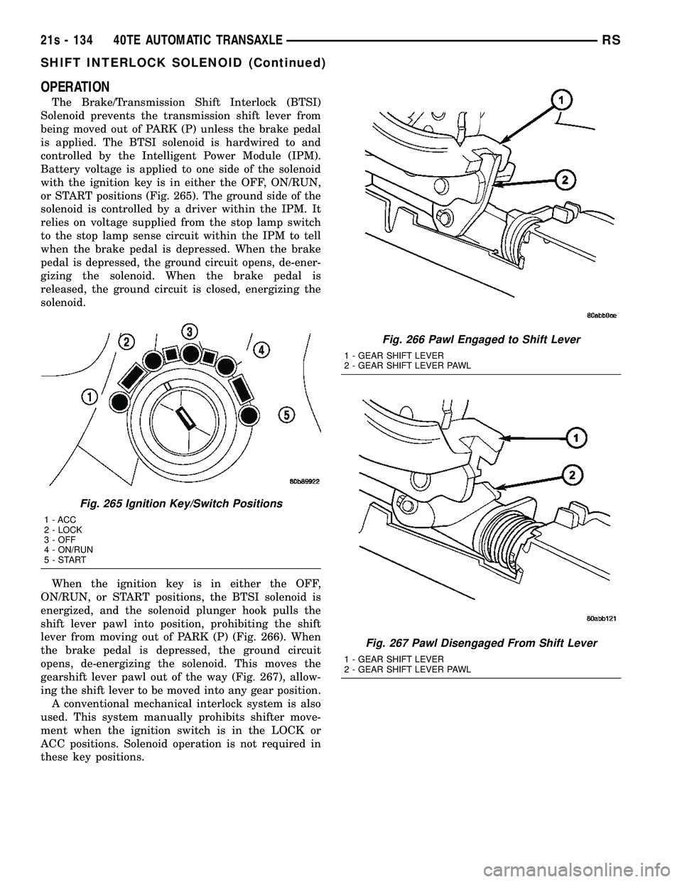
OPERATION
The Brake/Transmission Shift Interlock (BTSI)
Solenoid prevents the transmission shift lever from
being moved out of PARK (P) unless the brake pedal
is applied. The BTSI solenoid is hardwired to and
controlled by the Intelligent Power Module (IPM).
Battery voltage is applied to one side of the solenoid
with the ignition key is in either the OFF, ON/RUN,
or START positions (Fig. 265). The ground side of the
solenoid is controlled by a driver within the IPM. It
relies on voltage supplied from the stop lamp switch
to the stop lamp sense circuit within the IPM to tell
when the brake pedal is depressed. When the brake
pedal is depressed, the ground circuit opens, de-ener-
gizing the solenoid. When the brake pedal is
released, the ground circuit is closed, energizing the
solenoid.
When the ignition key is in either the OFF,
ON/RUN, or START positions, the BTSI solenoid is
energized, and the solenoid plunger hook pulls the
shift lever pawl into position, prohibiting the shift
lever from moving out of PARK (P) (Fig. 266). When
the brake pedal is depressed, the ground circuit
opens, de-energizing the solenoid. This moves the
gearshift lever pawl out of the way (Fig. 267), allow-
ing the shift lever to be moved into any gear position. A conventional mechanical interlock system is also
used. This system manually prohibits shifter move-
ment when the ignition switch is in the LOCK or
ACC positions. Solenoid operation is not required in
these key positions.
Fig. 265 Ignition Key/Switch Positions
1 - ACC
2 - LOCK
3 - OFF
4 - ON/RUN
5-START
Fig. 266 Pawl Engaged to Shift Lever
1 - GEAR SHIFT LEVER
2 - GEAR SHIFT LEVER PAWL
Fig. 267 Pawl Disengaged From Shift Lever
1 - GEAR SHIFT LEVER
2 - GEAR SHIFT LEVER PAWL
21s - 134 40TE AUTOMATIC TRANSAXLERS
SHIFT INTERLOCK SOLENOID (Continued)
Page 1998 of 2585

(3) Install steering column lower shroud.
(4) Install knee bolster (Fig. 274).
(5) Install instrument panel lower silencer (Fig.
275).
(6) Connect battery negative cable.
(7) Verify proper shift interlock system operation.
(Refer to 21 - TRANSMISSION/TRANSAXLE/AUTO-
MATIC - 31TH/SHIFT INTERLOCK SOLENOID -
OPERATION)
SOLENOID/PRESSURE
SWITCH ASSY
DESCRIPTION
The Solenoid/Pressure Switch Assembly (Fig. 276)
is external to the transaxle and mounted to the transaxle case. The assembly consists of four sole-
noids that control hydraulic pressure to the LR/CC,
2/4, OD, and UD friction elements. The reverse
clutch is controlled by line pressure from the manual
valve in the valve body. The solenoids are contained
within the Solenoid/Pressure Switch Assembly, and
can only be serviced by replacing the assembly.
The solenoid assembly also contains pressure
switches that monitor and send hydraulic circuit
information to the PCM/TCM. Likewise, the pressure
switches can only be service by replacing the assem-
bly.
OPERATION
SOLENOIDS
The solenoids receive electrical power from the
Transmission Control Relay through a single wire.
The PCM/TCM energizes or operates the solenoids
individually by grounding the return wire of the sole-
noid needed. When a solenoid is energized, the sole-
noid valve shifts, and a fluid passage is opened or
closed (vented or applied), depending on its default
operating state. The result is an apply or release of a
frictional element. The 2/4 and UD solenoids are normally applied,
which by design allow fluid to pass through in their
relaxed or ªoffº state. This allows transaxle limp-in
(P,R,N,2) in the event of an electrical failure. The continuity of the solenoids and circuits are
periodically tested. Each solenoid is turned on or off
depending on its current state. An inductive spike
Fig. 274 Knee Bolster
1 - KNEE BOLSTER
Fig. 275 Instrument Panel Lower Silencer
1 - INSTRUMENT PANEL LOWER SILENCER
Fig. 276 Solenoid/Pressure Switch Assembly
1 - SOLENOID AND PRESSURE SWITCH ASSEMBLY
RS 40TE AUTOMATIC TRANSAXLE21s - 137
SHIFT INTERLOCK SOLENOID (Continued)
Page 2081 of 2585

unique wheel weights. They are designed to fit the
contour of the wheel (Fig. 1).
²Inspect tires and wheels for damage, mud pack-
ing and unusual wear; correct as necessary.
²Check and adjust tire air pressure to the pres-
sure listed on the label attached to the rear face of
the driver's door.
ROAD TEST
Road test vehicle on a smooth road for a least five
miles to warm tires (remove any flat spots). Lightly
place hands on steering wheel at the 10:00 and 2:00
positions while slowly sweeping up and down from 90
to 110 km/h (55 to 70 mph) where legal speed limits
allow.
Observe the steering wheel for:
²Visual Nibble (oscillation: clockwise/counter-
clockwise, usually due to tire imbalance)
²Visual Buzziness (high frequency, rapid vibra-
tion up and down)
To rule out vibrations due to brakes or powertrain:
²Lightly apply brakes at speed; if vibration occurs
or is enhanced, vibration is likely due to causes other
than tire and wheel assemblies.
²Shift transmission into neutral while vibration
is occurring; if vibration is eliminated, vibration is
likely due to causes other than tire and wheel assem-
blies.
For brake vibrations, (Refer to 5 - BRAKES -
BASE/HYDRAULIC/MECHANICAL/ROTORS -
DIAGNOSIS AND TESTING).
For powertrain vibrations, (Refer to 3 - DIFFER-
ENTIAL & DRIVELINE - DIAGNOSIS AND TEST-
ING).
For tire and wheel assembly vibrations, continue
with this diagnosis and testing procedure.
TIRE AND WHEEL BALANCE
(1) Balance the tire and wheel assemblies as nec-
essary following the wheel balancer manufacturer's
instructions and using the information listed in Stan-
dard Procedure - Tire And Wheel Balance. (Refer to
22 - TIRES/WHEELS - STANDARD PROCEDURE)
(2) Road test the vehicle for at least 5 miles, fol-
lowing the format described in Road Test.
(3) If the vibration persists, continue with this
diagnosis and testing procedure.
TIRE AND WHEEL RUNOUT/MATCH MOUNTING
(1)System Radial Runout.This on-the-vehicle
system check will measure the radial runout includ-
ing the hub, wheel and tire.
(a) Raise vehicle so tires clear floor. (Refer to
LUBRICATION & MAINTENANCE/HOISTING -
STANDARD PROCEDURE)
(b) Apply masking tape around the circumfer-
ence of the tire in the locations to be measured
(Fig. 2). Do not overlap the tape.
(c) Check system runout using Dial Indicator
Set, Special Tool C-3339A with 25-W wheel, or
equivalent. Place the end of the indicator against
each taped area (one at a time) (Fig. 2) and rotate
the tire and wheel. System radial runout should
not exceed 0.76 mm (0.030 inch) with no tread
ªdipsº or ªsteps.º Tread ªdipsº and ªstepsº can be
identified by spikes of the dial indicator gauge.
²Tread9dips9; Rapid decrease then increase in
dial indicator reading over 101.6 mm (4.0 inch) of
tread circumference.
²Tread9steps9; Rapid decrease or increase in dial
indicator reading over 101.6 mm (4.0 inch) of tread
circumference.
(d) If system runout is excessive, re-index the
tire and wheel assembly on the hub. Remove
assembly from vehicle and install it back on the
hub two studs over from original mounting posi-
tion. If re-indexing the tire and wheel assembly
corrects or reduces system runout, check hub
runout and repair as necessary (Refer to 5 -
BRAKES - BASE/HYDRAULIC/MECHANICAL/
ROTORS - DIAGNOSIS AND TESTING).
(e) If system runout is still excessive, continue
with this diagnosis and testing procedure.
(2)Tire and Wheel Assembly Radial Runout.
This radial runout check is performed with the tire
and wheel assembly off the vehicle.
(a) Remove tire and wheel assembly from vehicle
and install it on a suitable wheel balancer.
(b) Check system runout using Dial Indicator
Set, Special Tool C-3339A with 25-W wheel, or
equivalent. Place the end of the indicator against
each taped area (one at a time) (Fig. 2) and rotate
the tire and wheel. Radial runout should not
Fig. 1 Aluminum Wheel Weight
1 - TIRE
2 - WHEEL
3 - WHEEL WEIGHT
22 - 2 TIRES/WHEELSRS
TIRES/WHEELS (Continued)
Page 2130 of 2585
(10) Verify door latch and power door lock opera-
tion.
(11) Install watershield and front door trim panel.
LATCH STRIKER
REMOVAL
(1) Mark outline of door striker on B-pillar to aid
in installation.
(2) Remove screws attaching door latch striker to
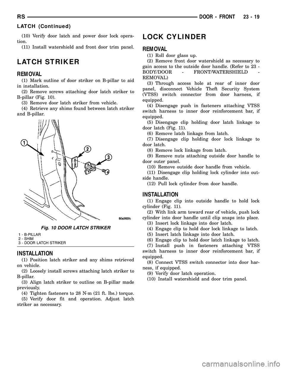
B-pillar (Fig. 10).
(3) Remove door latch striker from vehicle.
(4) Retrieve any shims found between latch striker
and B-pillar.
INSTALLATION
(1) Position latch striker and any shims retrieved
on vehicle.
(2) Loosely install screws attaching latch striker to
B-pillar.
(3) Align latch striker to outline on B-pillar made
previously.
(4) Tighten fasteners to 28 N´m (21 ft. lbs.) torque.
(5) Verify door fit and operation. Adjust latch
striker as necessary.
LOCK CYLINDER
REMOVAL
(1) Roll door glass up.
(2) Remove front door watershield as necessary to
gain access to the outside door handle. (Refer to 23 -
BODY/DOOR - FRONT/WATERSHIELD -
REMOVAL)
(3) Through access hole at rear of inner door
panel, disconnect Vehicle Theft Security System
(VTSS) switch connector from door harness, if
equipped.
(4) Disengage push in fasteners attaching VTSS
switch harness to inner door reinforcement bar, if
equipped.
(5) Disengage clip holding door latch linkage to
door latch (Fig. 11).
(6) Remove latch linkage from latch.
(7) Disengage clip holding door lock linkage to
door latch.
(8) Remove lock linkage from latch.
(9) Remove nuts attaching outside door handle to
door outer panel.
(10) Remove outside door handle from vehicle.
(11) Disengage clip holding lock cylinder into out-
side handle.
(12) Pull lock cylinder from door handle.
INSTALLATION
(1) Engage clip into outside handle to hold lock
cylinder (Fig. 11).
(2) With link arm toward rear of vehicle, push lock
cylinder into door handle until clip snaps into place.
(3) Insert lock linkage into door latch.
(4) Engage clip to hold door lock linkage to latch.
(5) Insert latch linkage into door latch.
(6) Engage clip to hold door latch linkage to latch.
(7) Install push in fasteners attaching VTSS
switch harness to inner door reinforcement bar, if
equipped.
(8) Connect VTSS switch connector into door har-
ness, if equipped.
(9) Verify door latch operation.
(10) Install watershield and door trim panel.
Fig. 10 DOOR LATCH STRIKER
1 - B-PILLAR
2 - SHIM
3 - DOOR LATCH STRIKER
RSDOOR - FRONT23-19
LATCH (Continued)
Page 2132 of 2585
(4) Place front door trim panel in position on door.
(5) Install trim panel into inner belt molding at
top of door.
(6) Install clips to attach door trim to door frame
around perimeter of panel.
(7) If equipped, install screw to attach door trim to
door panel behind inside latch release handle.
(8) If equipped, connect power switch into wire
connector.
(9) Place power accessary switch in position on
door trim.
(10) Connect wire connector into memory seat/mir-
ror switch and install switch into trim panel.
(11) Install screws to attach accessary switch
panel to door trim.
(12) Install screw cover into switch panel.
(13) If equipped, install window crank.
(14) If equipped, install screws to attach trim
panel to door inside map pocket.
(15) If equipped, install screw to attach door pull
cup to inner door panel.
(16) If equipped, install screws to attach door
assist handle to inner door panel.
(17) Connect wire connector into courtesy lamp.
(18) Install lamp in door trim.
(19) Install switch bezel.
WATERSHIELD
REMOVAL
(1) Remove door trim panel. (Refer to 23 - BODY/
DOOR - FRONT/TRIM PANEL - REMOVAL)
(2) Remove the front door speaker. (Refer to 8 -
ELECTRICAL/AUDIO/SPEAKER - REMOVAL)
(3) Peel watershield away from adhesive around
perimeter of inner door panel.
INSTALLATION
(1) Insure that enough adhesive remains to
securely retain the water dam. Replace as necessary.
(2) Place the shield into position and press
securely to adhesive making sure to properly route
wiring and linkages.
(3) Install the front door speaker. (Refer to 8 -
ELECTRICAL/AUDIO/SPEAKER - INSTALLATION)
(4) Install door trim panel. (Refer to 23 - BODY/
DOOR - FRONT/TRIM PANEL - INSTALLATION)
WINDOW CRANK
REMOVAL
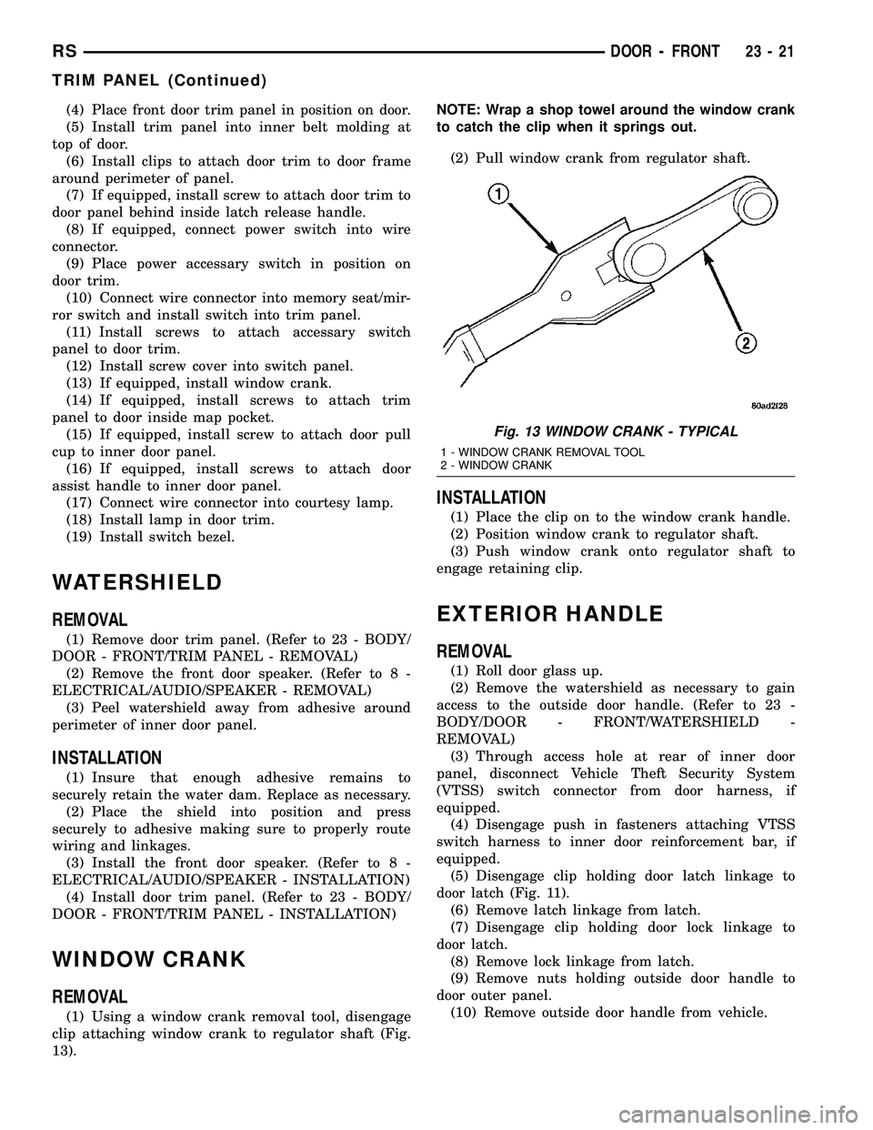
(1) Using a window crank removal tool, disengage
clip attaching window crank to regulator shaft (Fig.
13).NOTE: Wrap a shop towel around the window crank
to catch the clip when it springs out.
(2) Pull window crank from regulator shaft.
INSTALLATION
(1) Place the clip on to the window crank handle.
(2) Position window crank to regulator shaft.
(3) Push window crank onto regulator shaft to
engage retaining clip.
EXTERIOR HANDLE
REMOVAL
(1) Roll door glass up.
(2) Remove the watershield as necessary to gain
access to the outside door handle. (Refer to 23 -
BODY/DOOR - FRONT/WATERSHIELD -
REMOVAL)
(3) Through access hole at rear of inner door
panel, disconnect Vehicle Theft Security System
(VTSS) switch connector from door harness, if
equipped.
(4) Disengage push in fasteners attaching VTSS
switch harness to inner door reinforcement bar, if
equipped.
(5) Disengage clip holding door latch linkage to
door latch (Fig. 11).
(6) Remove latch linkage from latch.
(7) Disengage clip holding door lock linkage to
door latch.
(8) Remove lock linkage from latch.
(9) Remove nuts holding outside door handle to
door outer panel.
(10) Remove outside door handle from vehicle.
Fig. 13 WINDOW CRANK - TYPICAL
1 - WINDOW CRANK REMOVAL TOOL
2 - WINDOW CRANK
RSDOOR - FRONT23-21
TRIM PANEL (Continued)
Page 2135 of 2585
DOORS - SLIDING
TABLE OF CONTENTS
page page
CENTER HINGE
REMOVAL.............................24
INSTALLATION.........................24
SLIDING DOOR STOP BUMPER BEZEL
REMOVAL.............................25
INSTALLATION.........................25
STOP BUMPER
REMOVAL.............................25
INSTALLATION.........................25
HOLD OPEN LATCH
REMOVAL.............................25
INSTALLATION.........................25
HOLD OPEN LATCH STRIKER
REMOVAL.............................26
INSTALLATION.........................26
LATCH / LOCK ASSEMBLY
REMOVAL.............................26
INSTALLATION.........................27
INSIDE HANDLE ACTUATOR
REMOVAL.............................27
INSTALLATION.........................27
CENTER STRIKER
REMOVAL.............................28
INSTALLATION.........................28
LOWER HINGE
REMOVAL.............................28
INSTALLATION.........................28
REAR LATCH STRIKER
REMOVAL.............................29
INSTALLATION.........................29
SLIDING DOOR
REMOVAL.............................29
INSTALLATION.........................30ADJUSTMENTS
SLIDING DOOR ADJUSTMENTS..........30
STABILIZER
REMOVAL.............................33
INSTALLATION.........................33
STABILIZER SOCKET
REMOVAL.............................33
INSTALLATION.........................33
TRIM PANEL
REMOVAL.............................33
INSTALLATION.........................34
INSIDE LATCH HANDLE
REMOVAL.............................34
INSTALLATION.........................34
BELLCRANK
REMOVAL.............................35
INSTALLATION.........................35
OUTSIDE HANDLE
REMOVAL.............................35
INSTALLATION.........................35
UPPER HINGE
REMOVAL.............................36
INSTALLATION.........................36
OUTSIDE HANDLE CABLE
REMOVAL.............................37
INSTALLATION.........................37
INSIDE HANDLE CABLE
REMOVAL.............................37
INSTALLATION.........................38
HOLD OPEN LATCH CABLE
REMOVAL.............................38
INSTALLATION.........................38
CENTER HINGE
REMOVAL
NOTE: For power sliding door procedures refer to
POWER SLIDING DOOR SYSTEM in the ELECTRI-
CAL section.
(1) Open sliding door to the mid point of its travel.
(2) Support sliding door on a suitable lifting
device.
(3) Mark outline of center hinge of inner door
panel to aid installation.(4) Remove bolts attaching center hinge to sliding
door.
(5) Remove center hinge from sliding door.
(6) Roll center hinge to rear of roller channel.
(7) Remove center hinge from vehicle.
INSTALLATION
NOTE: For power sliding door procedures refer to
POWER SLIDING DOOR SYSTEM in the ELECTRI-
CAL section.
23 - 24 DOORS - SLIDINGRS
Page 2137 of 2585
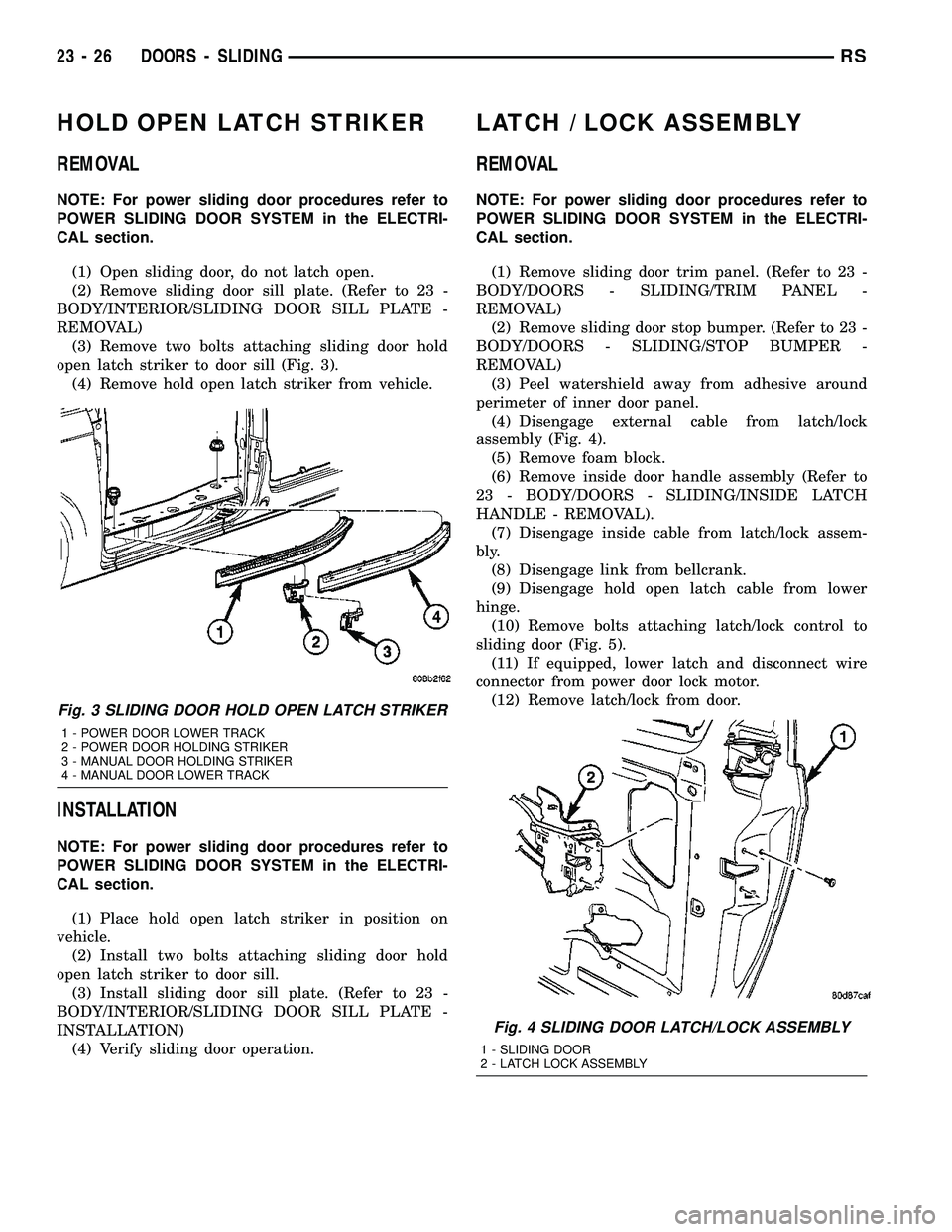
HOLD OPEN LATCH STRIKER
REMOVAL
NOTE: For power sliding door procedures refer to
POWER SLIDING DOOR SYSTEM in the ELECTRI-
CAL section.
(1) Open sliding door, do not latch open.
(2) Remove sliding door sill plate. (Refer to 23 -
BODY/INTERIOR/SLIDING DOOR SILL PLATE -
REMOVAL)
(3) Remove two bolts attaching sliding door hold
open latch striker to door sill (Fig. 3).
(4) Remove hold open latch striker from vehicle.
INSTALLATION
NOTE: For power sliding door procedures refer to
POWER SLIDING DOOR SYSTEM in the ELECTRI-
CAL section.
(1) Place hold open latch striker in position on
vehicle.
(2) Install two bolts attaching sliding door hold
open latch striker to door sill.
(3) Install sliding door sill plate. (Refer to 23 -
BODY/INTERIOR/SLIDING DOOR SILL PLATE -
INSTALLATION)
(4) Verify sliding door operation.
LATCH / LOCK ASSEMBLY
REMOVAL
NOTE: For power sliding door procedures refer to
POWER SLIDING DOOR SYSTEM in the ELECTRI-
CAL section.
(1) Remove sliding door trim panel. (Refer to 23 -
BODY/DOORS - SLIDING/TRIM PANEL -
REMOVAL)
(2) Remove sliding door stop bumper. (Refer to 23 -
BODY/DOORS - SLIDING/STOP BUMPER -
REMOVAL)
(3) Peel watershield away from adhesive around
perimeter of inner door panel.
(4) Disengage external cable from latch/lock
assembly (Fig. 4).
(5) Remove foam block.
(6) Remove inside door handle assembly (Refer to
23 - BODY/DOORS - SLIDING/INSIDE LATCH
HANDLE - REMOVAL).
(7) Disengage inside cable from latch/lock assem-
bly.
(8) Disengage link from bellcrank.
(9) Disengage hold open latch cable from lower
hinge.
(10) Remove bolts attaching latch/lock control to
sliding door (Fig. 5).
(11) If equipped, lower latch and disconnect wire
connector from power door lock motor.
(12) Remove latch/lock from door.
Fig. 3 SLIDING DOOR HOLD OPEN LATCH STRIKER
1 - POWER DOOR LOWER TRACK
2 - POWER DOOR HOLDING STRIKER
3 - MANUAL DOOR HOLDING STRIKER
4 - MANUAL DOOR LOWER TRACK
Fig. 4 SLIDING DOOR LATCH/LOCK ASSEMBLY
1 - SLIDING DOOR
2 - LATCH LOCK ASSEMBLY
23 - 26 DOORS - SLIDINGRS
Page 2138 of 2585
INSTALLATION
NOTE: For power sliding door procedures refer to
POWER SLIDING DOOR SYSTEM in the ELECTRI-
CAL section.
(1) Position latch/lock locking lever in unlocked
position.
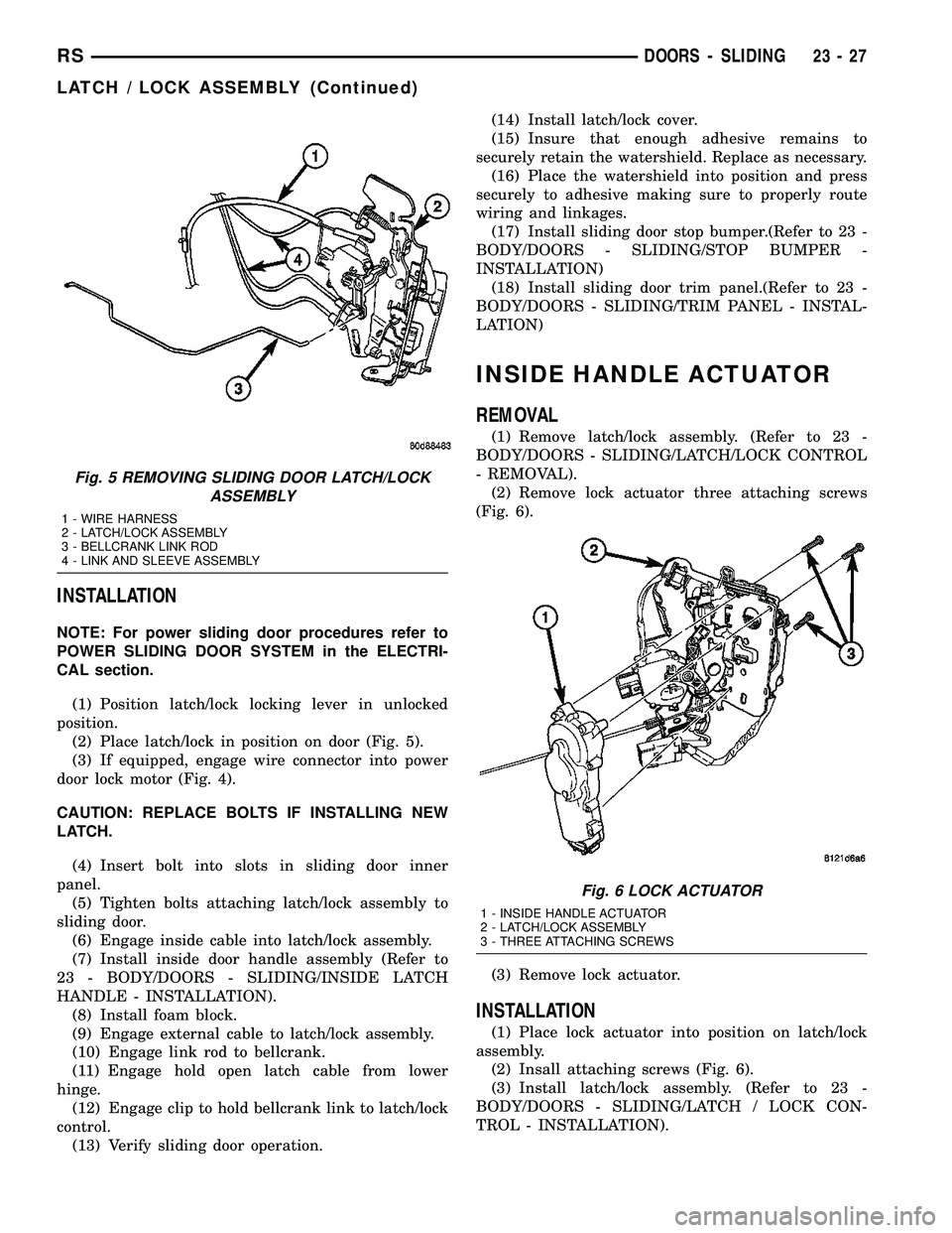
(2) Place latch/lock in position on door (Fig. 5).
(3) If equipped, engage wire connector into power
door lock motor (Fig. 4).
CAUTION: REPLACE BOLTS IF INSTALLING NEW
LATCH.
(4) Insert bolt into slots in sliding door inner
panel.
(5) Tighten bolts attaching latch/lock assembly to
sliding door.
(6) Engage inside cable into latch/lock assembly.
(7) Install inside door handle assembly (Refer to
23 - BODY/DOORS - SLIDING/INSIDE LATCH
HANDLE - INSTALLATION).
(8) Install foam block.
(9) Engage external cable to latch/lock assembly.
(10) Engage link rod to bellcrank.
(11) Engage hold open latch cable from lower
hinge.
(12) Engage clip to hold bellcrank link to latch/lock
control.
(13) Verify sliding door operation.(14) Install latch/lock cover.
(15) Insure that enough adhesive remains to
securely retain the watershield. Replace as necessary.
(16) Place the watershield into position and press
securely to adhesive making sure to properly route
wiring and linkages.
(17) Install sliding door stop bumper.(Refer to 23 -
BODY/DOORS - SLIDING/STOP BUMPER -
INSTALLATION)
(18) Install sliding door trim panel.(Refer to 23 -
BODY/DOORS - SLIDING/TRIM PANEL - INSTAL-
LATION)
INSIDE HANDLE ACTUATOR
REMOVAL
(1) Remove latch/lock assembly. (Refer to 23 -
BODY/DOORS - SLIDING/LATCH/LOCK CONTROL
- REMOVAL).
(2) Remove lock actuator three attaching screws
(Fig. 6).
(3) Remove lock actuator.
INSTALLATION
(1) Place lock actuator into position on latch/lock
assembly.
(2) Insall attaching screws (Fig. 6).
(3) Install latch/lock assembly. (Refer to 23 -
BODY/DOORS - SLIDING/LATCH / LOCK CON-
TROL - INSTALLATION).
Fig. 5 REMOVING SLIDING DOOR LATCH/LOCK
ASSEMBLY
1 - WIRE HARNESS
2 - LATCH/LOCK ASSEMBLY
3 - BELLCRANK LINK ROD
4 - LINK AND SLEEVE ASSEMBLY
Fig. 6 LOCK ACTUATOR
1 - INSIDE HANDLE ACTUATOR
2 - LATCH/LOCK ASSEMBLY
3 - THREE ATTACHING SCREWS
RSDOORS - SLIDING23-27
LATCH / LOCK ASSEMBLY (Continued)
Page 2139 of 2585
CENTER STRIKER
REMOVAL
(1) Remove sliding door trim panel. (Refer to 23 -
BODY/DOORS - SLIDING/TRIM PANEL -
REMOVAL)
(2) Remove bolts attaching stop bumper. Remove
stop bumper from door.
(3) Remove screws attaching center striker assem-
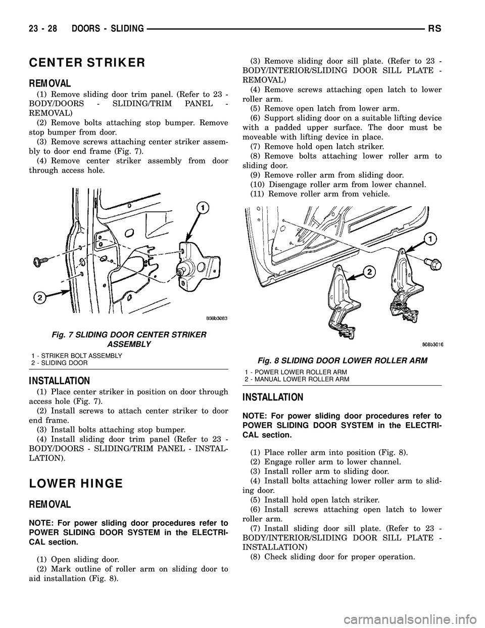
bly to door end frame (Fig. 7).
(4) Remove center striker assembly from door
through access hole.
INSTALLATION
(1) Place center striker in position on door through
access hole (Fig. 7).
(2) Install screws to attach center striker to door
end frame.
(3) Install bolts attaching stop bumper.
(4) Install sliding door trim panel (Refer to 23 -
BODY/DOORS - SLIDING/TRIM PANEL - INSTAL-
LATION).
LOWER HINGE
REMOVAL
NOTE: For power sliding door procedures refer to
POWER SLIDING DOOR SYSTEM in the ELECTRI-
CAL section.
(1) Open sliding door.
(2) Mark outline of roller arm on sliding door to
aid installation (Fig. 8).(3) Remove sliding door sill plate. (Refer to 23 -
BODY/INTERIOR/SLIDING DOOR SILL PLATE -
REMOVAL)
(4) Remove screws attaching open latch to lower
roller arm.
(5) Remove open latch from lower arm.
(6) Support sliding door on a suitable lifting device
with a padded upper surface. The door must be
moveable with lifting device in place.
(7) Remove hold open latch striker.
(8) Remove bolts attaching lower roller arm to
sliding door.
(9) Remove roller arm from sliding door.
(10) Disengage roller arm from lower channel.
(11) Remove roller arm from vehicle.
INSTALLATION
NOTE: For power sliding door procedures refer to
POWER SLIDING DOOR SYSTEM in the ELECTRI-
CAL section.
(1) Place roller arm into position (Fig. 8).
(2) Engage roller arm to lower channel.
(3) Install roller arm to sliding door.
(4) Install bolts attaching lower roller arm to slid-
ing door.
(5) Install hold open latch striker.
(6) Install screws attaching open latch to lower
roller arm.
(7) Install sliding door sill plate. (Refer to 23 -
BODY/INTERIOR/SLIDING DOOR SILL PLATE -
INSTALLATION)
(8) Check sliding door for proper operation.
Fig. 7 SLIDING DOOR CENTER STRIKER
ASSEMBLY
1 - STRIKER BOLT ASSEMBLY
2 - SLIDING DOORFig. 8 SLIDING DOOR LOWER ROLLER ARM
1 - POWER LOWER ROLLER ARM
2 - MANUAL LOWER ROLLER ARM
23 - 28 DOORS - SLIDINGRS
Page 2140 of 2585
REAR LATCH STRIKER
REMOVAL
(1) Open sliding door.
(2) Mark outline of striker on C-pillar door jamb
face to aid installation.
(3) Remove screws attaching striker to C-pillar
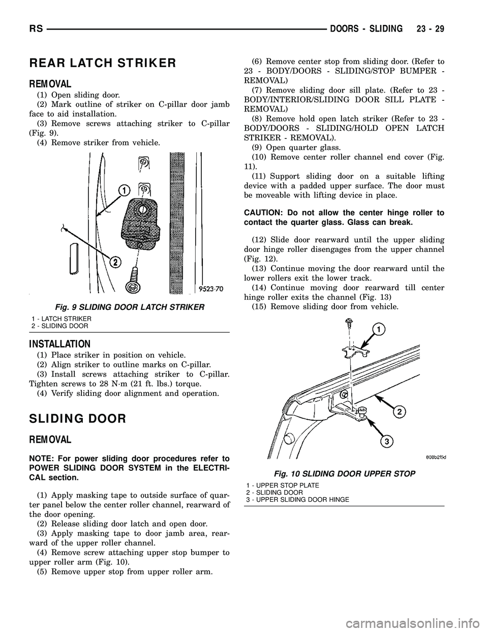
(Fig. 9).
(4) Remove striker from vehicle.
INSTALLATION
(1) Place striker in position on vehicle.
(2) Align striker to outline marks on C-pillar.
(3) Install screws attaching striker to C-pillar.
Tighten screws to 28 N´m (21 ft. lbs.) torque.
(4) Verify sliding door alignment and operation.
SLIDING DOOR
REMOVAL
NOTE: For power sliding door procedures refer to
POWER SLIDING DOOR SYSTEM in the ELECTRI-
CAL section.
(1) Apply masking tape to outside surface of quar-
ter panel below the center roller channel, rearward of
the door opening.
(2) Release sliding door latch and open door.
(3) Apply masking tape to door jamb area, rear-
ward of the upper roller channel.
(4) Remove screw attaching upper stop bumper to
upper roller arm (Fig. 10).
(5) Remove upper stop from upper roller arm.(6) Remove center stop from sliding door. (Refer to
23 - BODY/DOORS - SLIDING/STOP BUMPER -
REMOVAL)
(7) Remove sliding door sill plate. (Refer to 23 -
BODY/INTERIOR/SLIDING DOOR SILL PLATE -
REMOVAL)
(8) Remove hold open latch striker (Refer to 23 -
BODY/DOORS - SLIDING/HOLD OPEN LATCH
STRIKER - REMOVAL).
(9) Open quarter glass.
(10) Remove center roller channel end cover (Fig.
11).
(11) Support sliding door on a suitable lifting
device with a padded upper surface. The door must
be moveable with lifting device in place.
CAUTION: Do not allow the center hinge roller to
contact the quarter glass. Glass can break.
(12) Slide door rearward until the upper sliding
door hinge roller disengages from the upper channel
(Fig. 12).
(13) Continue moving the door rearward until the
lower rollers exit the lower track.
(14) Continue moving door rearward till center
hinge roller exits the channel (Fig. 13)
(15) Remove sliding door from vehicle.
Fig. 9 SLIDING DOOR LATCH STRIKER
1 - LATCH STRIKER
2 - SLIDING DOOR
Fig. 10 SLIDING DOOR UPPER STOP
1 - UPPER STOP PLATE
2 - SLIDING DOOR
3 - UPPER SLIDING DOOR HINGE
RSDOORS - SLIDING23-29