8e electrical CHRYSLER VOYAGER 2004 Owner's Manual
[x] Cancel search | Manufacturer: CHRYSLER, Model Year: 2004, Model line: VOYAGER, Model: CHRYSLER VOYAGER 2004Pages: 2585, PDF Size: 62.54 MB
Page 285 of 2585
(24) Install knee blocker reinforcement plate (Fig.
53). (25) Connect parking brake release link to release
handle. (26) Install data link diagnostic connector to
mounting hole in reinforcement plate. (27) Install lower steering column cover/knee
blocker (Fig. 53). (28) Install throttle cable onto throttle body lever.
(Refer to 14 - FUEL SYSTEM/FUEL INJECTION/
THROTTLE CONTROL CABLE - INSTALLATION)
NOTE: When reconnecting the battery on a vehicle
that has had the airbag module removed, the fol-
lowing procedure should be used.
(29) Reconnect ground cable to negative post of
battery following special Diagnosis And Testing pro-
cedure. (Refer t o 8 - ELECTRICAL/RESTRAINTS -
DIAGNOSIS AND TESTING) (30) Test operation of adjustable pedals and all
functions that are steering column operated. If appli-
cable, reset radio and clock. (31) Road test the vehicle to ensure proper opera-
tion of steering and brake systems.
PEDAL TORQUE SHAFT - RHD
REMOVAL
(1) Remove the instrument panel. (Refer to 23 -
BODY/INSTRUMENT PANEL/INSTRUMENT
PANEL ASSEMBLY - REMOVAL) (2) Remove the HVAC housing. (Refer to 24 -
HEATING & AIR CONDITIONING/DISTRIBUTION/
HVAC HOUSING - REMOVAL) (3) Remove the retaining clip at the torque shaft
end of the brake pedal-to-torque shaft link. Remove
the link from the torque shaft. Discard the retaining
clip. It is not to be reused. Replace with a new clip
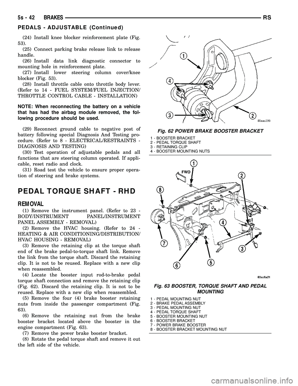
when reassembled. (4) Locate the booster input rod-to-brake pedal
torque shaft connection and remove the retaining clip
(Fig. 62). Discard the retaining clip. It is not to be
reused. Replace with a new clip when reassembled. (5) Remove the four (4) brake booster retaining
nuts from inside the passenger compartment (Fig.
63). (6) Remove the retaining nut from the brake
booster bracket located above the booster in the
engine compartment (Fig. 63). (7) Remove the power brake booster bracket.
(8) Rotate the pedal torque shaft and remove it out
the left side of the vehicle.
Fig. 62 POWER BRAKE BOOSTER BRACKET
1 - BOOSTER BRACKET
2 - PEDAL TORQUE SHAFT
3 - RETAINING CLIP
4 - BOOSTER MOUNTING NUTS
Fig. 63 BOOSTER, TORQUE SHAFT AND PEDAL MOUNTING
1 - PEDAL MOUNTING NUT
2 - BRAKE PEDAL ASSEMBLY
3 - PEDAL MOUNTING NUT
4 - PEDAL TORQUE SHAFT
5 - BOOSTER MOUNTING NUT
6 - BOOSTER BRACKET
7 - POWER BRAKE BOOSTER
8 - BOOSTER BRACKET MOUNTING NUT
5s - 42 BRAKESRS
PEDALS - ADJUSTABLE (Continued)
Page 286 of 2585
INSTALLATION
(1) Lubricate both ends of the torque shaft with
MS-4517 Lubricant or equivalent and install the
torque shaft from the left side reversing the removal
procedure. (2) Install the brake booster bracket on the left
end of the shaft. (3) Install the retaining nut for the brake booster
bracket in the engine compartment. Tighten the
mounting nut to a torque of 29 N´m (250 in. lbs.). (4) Install the four brake booster retaining nuts
inside the passenger compartment. Tighten the
mounting nuts to a torque of 29 N´m (250 in. lbs.). (5) Using lubriplate, or equivalent, coat the sur-
face of the brake pedal torque shaft pin where it con-
tacts the booster input rod. Also coat the surface of
the brake pedal torque shaft pin where it contacts
the brake pedal link.
CAUTION: When installing the power brake booster
input rod on the brake pedal torque shaft pin, do
not reuse the old retaining clip.
(6) Install booster input rod on brake pedal torque
shaft pin and install a NEW retaining clip (Fig. 62).
CAUTION: When installing the brake pedal link on
the brake pedal torque shaft pin, do not reuse the
old retaining clip.
(7) Connect the brake pedal link to the torque
shaft. Install a NEW retaining clip at the torque
shaft end of the brake pedal-to-torque shaft link. (8) Install the HVAC housing. (Refer to 24 - HEAT-
ING & AIR CONDITIONING/DISTRIBUTION/HVAC
HOUSING - INSTALLATION) (9) Install the instrument panel. (Refer to 23 -
BODY/INSTRUMENT PANEL/INSTRUMENT
PANEL ASSEMBLY - INSTALLATION)
CAUTION: Do not reuse the original brake lamp
switch. The switch can only be adjusted once. That
is during initial installation of the switch. If the
switch is not adjusted properly or has been
removed for some service, a new switch must be
installed and adjusted.
(10) Remove and replace the brake lamp switch
with a NEW switch. (Refer t o 8 - ELECTRICAL/
LAMPS/LIGHTING - EXTERIOR/BRAKE LAMP
SWITCH - REMOVAL), (Refer t o 8 - ELECTRICAL/
LAMPS/LIGHTING - EXTERIOR/BRAKE LAMP
SWITCH - INSTALLATION) (11) Road test vehicle to ensure proper operation of
the brakes.
POWER BRAKE BOOSTER
DESCRIPTION
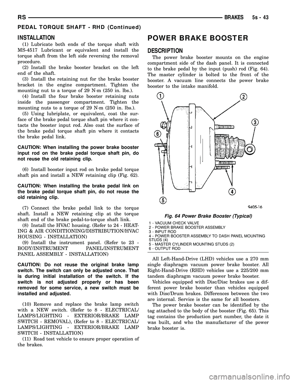
The power brake booster mounts on the engine
compartment side of the dash panel. It is connected
to the brake pedal by the input (push) rod (Fig. 64).
The master cylinder is bolted to the front of the
booster. A vacuum line connects the power brake
booster to the intake manifold.
All Left-Hand-Drive (LHD) vehicles use a 270 mm
single diaphragm vacuum power brake booster. All
Right-Hand-Drive (RHD) vehicles use a 225/200 mm
tandem diaphragm vacuum power brake booster. Vehicles equipped with Disc/Disc brakes use a dif-
ferent power brake booster than vehicles equipped
with Disc/Drum brakes. Differences between the two
are internal. Service is the same for all boosters. The power brake booster can be identified by the
tag attached to the body of the booster (Fig. 65). This
tag contains the production part number, the date it
was built, and who the manufacturer of the power
brake booster is.
Fig. 64 Power Brake Booster (Typical)
1 - VACUUM CHECK VALVE
2 - POWER BRAKE BOOSTER ASSEMBLY
3 - INPUT ROD
4 - POWER BOOSTER ASSEMBLY TO DASH PANEL MOUNTING
STUDS (4)
5 - MASTER CYLINDER MOUNTING STUDS (2)
6 - OUTPUT ROD
RS BRAKES5s-43
PEDAL TORQUE SHAFT - RHD (Continued)
Page 288 of 2585

(6) Apply light effort (approximately 15 lbs. of
force) to the brake pedal and hold the pedal steady.
Do not move the pedal once the pressure is applied
or the test results may vary. (7) Have an assistant reattach the vacuum line
pliers to the vacuum supply hose. (8) Allow 5 seconds for stabilization, then observe
the vacuum gauge. If the vacuum drop exceeds 3.0 inches Hg (10 kPa)
in 15 seconds, repeat the above steps to confirm the
reading. The vacuum loss should be less than 3.0
inches Hg in 15 seconds time span. If the loss is
more than 3.0 inches Hg, replace the power brake
booster. If it is not, the booster is not defective. (9) Remove the pliers and vacuum gauge.
REMOVAL
REMOVAL - LHD
CAUTION: Reserve vacuum in power brake booster
must be pumped down (removed) before removing
master cylinder from booster. This is necessary to
prevent booster from sucking in any contamination
as master cylinder is removed. This can be done
simply by pumping the brake pedal, with the vehi-
cle's engine not running, until a firm feeling brake
pedal is achieved.
(1) With engine not running, pump the brake
pedal until a firm pedal is achieved (4-5 strokes). (2) Remove negative battery cable terminal from
battery. (3) Remove positive battery cable terminal from
battery. (4) Remove battery thermal guard shield.
(5) Remove battery clamp, nut and battery from
the battery tray. (6) Remove screw securing engine coolant filler
tube to battery tray. (7) If the vehicle is equipped with speed control,
disconnect the vacuum hose at the vacuum tank built
into the battery tray. (8) Remove the two nuts and one bolt securing bat-
tery tray in place. Remove battery tray. (9) If vehicle is equipped with speed control:(a) Disconnect wiring harness connector from
the speed control servo. (b) Remove the two servo mounting nuts.
(c) Lay speed control servo off to the side, out of
the way.
(10) Remove the wiper module (unit). (Refer to 8 -
ELECTRICAL/WIPERS/WASHERS/WIPER MOD-
ULE - REMOVAL) (11) Disconnect wiring harness connector from
brake fluid level switch in master cylinder fluid res-
ervoir (Fig. 66).
CAUTION: Before removing the master cylinder
from the power brake vacuum booster, the master
cylinder and vacuum booster must be thoroughly
cleaned. This must be done to prevent dirt particles
from falling into the power brake vacuum booster.
(12) Clean area where master cylinder assembly
attaches to power brake booster. Use only a solvent
such as Mopar tBrake Parts Cleaner or equivalent.
(13) Disconnect primary and secondary brake
tubes from ABS integrated control unit or non-ABS
junction block (Fig. 67). Install sealing plugs in the
now open brake tube ports and install caps on ends
of tubes.
NOTE: It is not necessary to remove the brake
tubes from the master cylinder when removing the
master cylinder from the vacuum booster.
(14) Remove two nuts attaching master cylinder to
power brake booster (Fig. 67). (15) Slide master cylinder straight out of power
brake booster. Remove master cylinder with primary
and secondary tubes from vehicle.
CAUTION: A seal on the rear of the master cylinder
is used to create the seal for holding vacuum in the
power brake vacuum booster. The vacuum seal on
the master cylinder MUST be replaced whenever the
master cylinder is removed from the power brake
vacuum booster.
Fig. 66 Master Cylinder And Booster
1 - POWER BRAKE BOOSTER
2 - BOOSTER IDENTIFICATION LABEL
3 - FLUID LEVEL SWITCH CONNECTOR
4 - PRIMARY BRAKE TUBE NUT
5 - SECONDARY BRAKE TUBE NUT
6 - MASTER CYLINDER
RS BRAKES5s-45
POWER BRAKE BOOSTER (Continued)
Page 292 of 2585

INSTALLATION
INSTALLATION - LHD
(1) Position power brake booster on dash panel
using the reverse procedure of its removal (Fig. 70).
It may be necessary to push in on booster input rod
as it is guided through the dash panel. (2) Install the four nuts mounting the booster to
the dash panel (Fig. 69). Tighten the mounting nuts
to a torque of 29 N´m (250 in. lbs.). (3) Using lubriplate, or equivalent, coat the sur-
face of the brake pedal pin where it contacts the
booster input rod.
CAUTION: When installing the brake pedal pin on
the power brake booster input rod, do not re-use
the old retaining clip.
(4) Install booster input rod on brake pedal pin
and install a NEW retaining clip (Fig. 76).
CAUTION: Do not reuse the original brake lamp
switch. The switch can only be adjusted once. That
is during initial installation of the switch. If the
switch is not adjusted properly or has been
removed for some service, a new switch must be
installed and adjusted.
(5) Remove and replace the brake lamp switch
with a NEW switch. (Refer t o 8 - ELECTRICAL/
LAMPS/LIGHTING - EXTERIOR/BRAKE LAMP
SWITCH - REMOVAL), (Refer t o 8 - ELECTRICAL/
LAMPS/LIGHTING - EXTERIOR/BRAKE LAMP
SWITCH - INSTALLATION) (6) Install the silencer panel below the steering
column. (7) Connect vacuum hose to check valve on power
brake booster.
CAUTION: The master cylinder (and its rear seal) is
used to create the seal for holding vacuum in the
vacuum booster. The vacuum seal on the master
cylinder MUST be replaced with a NEW seal when-
ever the master cylinder is removed from the vac-
uum booster.
CAUTION: When removing the vacuum seal from
the master cylinder do not use a sharp tool.
(8) Using a soft tool such as a trim stick, remove
the vacuum seal from the master cylinder mounting
flange. (9) Install a NEW vacuum seal on rear mounting
flange of the master cylinder (Fig. 77).
(10) Position master cylinder on studs of booster,
aligning push rod on booster with master cylinder
piston. (11) Install the two nuts mounting the master cyl-
inder to the booster (Fig. 67). Tighten both mounting
nuts to a torque of 25 N´m (225 in. lbs.). (12) Connect wiring harness connector to brake
fluid level switch in the master cylinder fluid reser-
voir (Fig. 66). (13) Connect primary and secondary brake tubes
to ABS ICU or non-ABS junction block (Fig. 67).
Tighten the tube nuts to 17 N´m (145 in lbs.). (14) Install wiper module (unit). (Refer to 8 -
ELECTRICAL/WIPERS/WASHERS/WIPER MOD-
ULE - INSTALLATION) (15) If equipped with speed control, install speed
control servo and connect wiring connector. Tighten
Fig. 76 Retaining Pin Installed On Brake Pedal Pin
1 - BRAKE PEDAL
2 - RETAINING CLIP
3 - BOOSTER INPUT ROD
Fig. 77 Vacuum Seal (Typical)
1 - MASTER CYLINDER ASSEMBLY
2 - VACUUM SEAL
RS BRAKES5s-49
POWER BRAKE BOOSTER (Continued)
Page 294 of 2585
(11) Connect wiring harness connector to brake
fluid level switch in the master cylinder fluid reser-
voir (Fig. 71). (12) If the vehicle is equipped with the 2.5L diesel
engine, install the coolant recovery pressure con-
tainer and bracket. (Refer t o 7 - COOLING/ENGINE/
COOLANT RECOVERY PRESS CONTAINER -
INSTALLATION) (13) If equipped with speed control, install speed
control servo and connect wiring connector. Tighten
the mounting nuts to a torque of 14 N´m (124 in.
lbs.). (14) Install the battery tray. Install the two nuts
and one bolt attaching the battery tray to the vehicle.
Tighten the bolt and nuts to a torque of 14 N´m (124
in. lbs.). (15) If vehicle is equipped with speed control, con-
nect the servo vacuum hose to the vacuum tank on
the battery tray. (16) Install the battery, clamp and mounting nut.
(17) Install the positive battery cable on the bat-
tery. (18) Install the negative battery cable on the bat-
tery. (19) Install the battery thermal guard shield.
CAUTION: Do not reuse the original brake lamp
switch. The switch can only be adjusted once. That
is during initial installation of the switch. If the
switch is not adjusted properly or has been
removed for some service, a new switch must be
installed and adjusted. (20) Remove and replace the brake lamp switch
with a NEW switch. (Refer t o 8 - ELECTRICAL/
LAMPS/LIGHTING - EXTERIOR/BRAKE LAMP
SWITCH - REMOVAL), (Refer t o 8 - ELECTRICAL/
LAMPS/LIGHTING - EXTERIOR/BRAKE LAMP
SWITCH - INSTALLATION) (21) Bleed the base brakes as necessary. (Refer to
5 - BRAKES - STANDARD PROCEDURE) (22) Road test vehicle to ensure proper operation
of the brakes.
PROPORTIONING VALVE
DESCRIPTION - PROPORTIONING VALVE
(HEIGHT SENSING)
NOTE: Only vehicles without antilock brakes (ABS)
have a proportioning valve. Vehicles with ABS uti-
lize electronic brake distribution which is controlled
through the ABS integrated control unit.
Vehicles not equipped with ABS use a height sens-
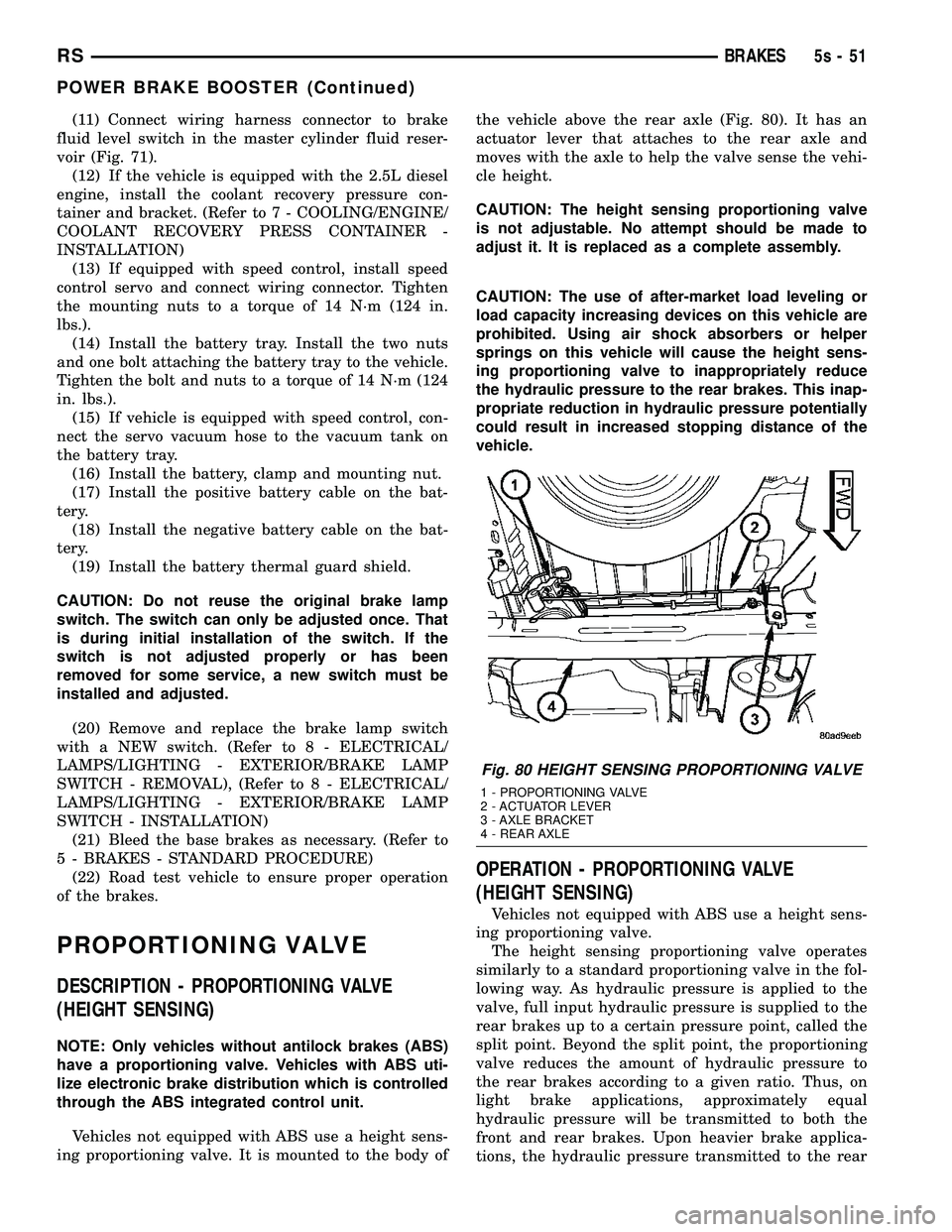
ing proportioning valve. It is mounted to the body of the vehicle above the rear axle (Fig. 80). It has an
actuator lever that attaches to the rear axle and
moves with the axle to help the valve sense the vehi-
cle height.
CAUTION: The height sensing proportioning valve
is not adjustable. No attempt should be made to
adjust it. It is replaced as a complete assembly.
CAUTION: The use of after-market load leveling or
load capacity increasing devices on this vehicle are
prohibited. Using air shock absorbers or helper
springs on this vehicle will cause the height sens-
ing proportioning valve to inappropriately reduce
the hydraulic pressure to the rear brakes. This inap-
propriate reduction in hydraulic pressure potentially
could result in increased stopping distance of the
vehicle.
OPERATION - PROPORTIONING VALVE
(HEIGHT SENSING)
Vehicles not equipped with ABS use a height sens-
ing proportioning valve. The height sensing proportioning valve operates
similarly to a standard proportioning valve in the fol-
lowing way. As hydraulic pressure is applied to the
valve, full input hydraulic pressure is supplied to the
rear brakes up to a certain pressure point, called the
split point. Beyond the split point, the proportioning
valve reduces the amount of hydraulic pressure to
the rear brakes according to a given ratio. Thus, on
light brake applications, approximately equal
hydraulic pressure will be transmitted to both the
front and rear brakes. Upon heavier brake applica-
tions, the hydraulic pressure transmitted to the rear
Fig. 80 HEIGHT SENSING PROPORTIONING VALVE
1 - PROPORTIONING VALVE
2 - ACTUATOR LEVER
3 - AXLE BRACKET
4 - REAR AXLE
RS BRAKES5s-51
POWER BRAKE BOOSTER (Continued)
Page 311 of 2585
(5) Install the park brake release rod on the
release mechanism of the park brake pedal. (6) Position the park brake pedal mechanism into
its installed position on the body of the vehicle. (7) Loosely install the top bolt mounting the park
brake pedal mechanism to the body (Fig. 111). (8) Loosely install the forward nut mounting the
park brake pedal mechanism to the body (Fig. 111). (9) Loosely install the lower bolt mounting the
park brake pedal mechanism to the body (Fig. 111). (10) Tighten pedal mechanism attaching bolts and
nut to 28 N´m (250 in. lbs.). (11) Verify that the park brake pedal is in the fully
released (full up) position. (12) Raise vehicle.
(13) Install the front park brake cable on the park
brake cable equalizer (Fig. 110).
NOTE: If the original lever assembly is being used,
the lever mechanism auto adjuster spring tension
will need to be reset. (Refer t o 5 - BRAKES/PARK-
ING BRAKE - STANDARD PROCEDURE)
(14) Lower vehicle.
(15) Remove the lock-out pin (if a new lever has
been installed) from the automatic cable adjuster on
the park brake pedal mechanism. (16) Install the electrical junction block on the
instrument panel. (17) Install the reinforcement on the lower instru-
ment panel. (18) Install the steering column lower cover on the
lower instrument panel. (19) Install the silencer panel under the instru-
ment panel. (20) Install the left side kick panel.
(21) Install the sill scuff plate on the lower sill of
the left door. (22) Install the negative (ground) cable on the bat-
tery. (23) Cycle the park brake pedal one time. This will
seat the park brake cables and will allow the auto-
matic self adjuster to properly tension the park brake
cables.
LEVER - PARKING BRAKE
(EXPORT)
REMOVAL - PARKING BRAKE LEVER AND
FRONT CABLE
(1) Raise vehicle. (Refer to LUBRICATION &
MAINTENANCE/HOISTING - STANDARD PROCE-
DURE) (2) Grasp the exposed section of the front parking
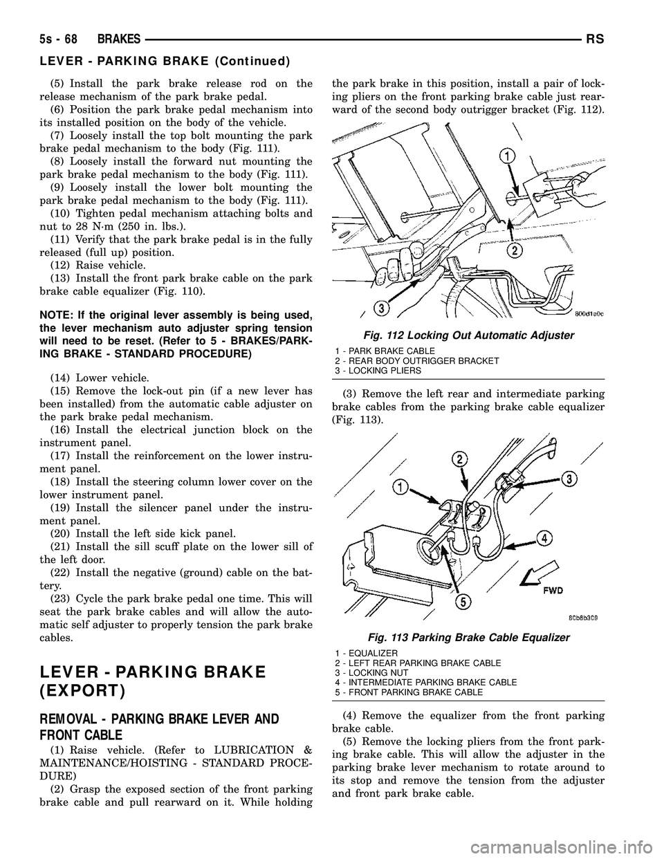
brake cable and pull rearward on it. While holding the park brake in this position, install a pair of lock-
ing pliers on the front parking brake cable just rear-
ward of the second body outrigger bracket (Fig. 112).
(3) Remove the left rear and intermediate parking
brake cables from the parking brake cable equalizer
(Fig. 113).
(4) Remove the equalizer from the front parking
brake cable. (5) Remove the locking pliers from the front park-
ing brake cable. This will allow the adjuster in the
parking brake lever mechanism to rotate around to
its stop and remove the tension from the adjuster
and front park brake cable.
Fig. 112 Locking Out Automatic Adjuster
1 - PARK BRAKE CABLE
2 - REAR BODY OUTRIGGER BRACKET
3 - LOCKING PLIERS
Fig. 113 Parking Brake Cable Equalizer
1 - EQUALIZER
2 - LEFT REAR PARKING BRAKE CABLE
3 - LOCKING NUT
4 - INTERMEDIATE PARKING BRAKE CABLE
5 - FRONT PARKING BRAKE CABLE
5s - 68 BRAKESRS
LEVER - PARKING BRAKE (Continued)
Page 329 of 2585
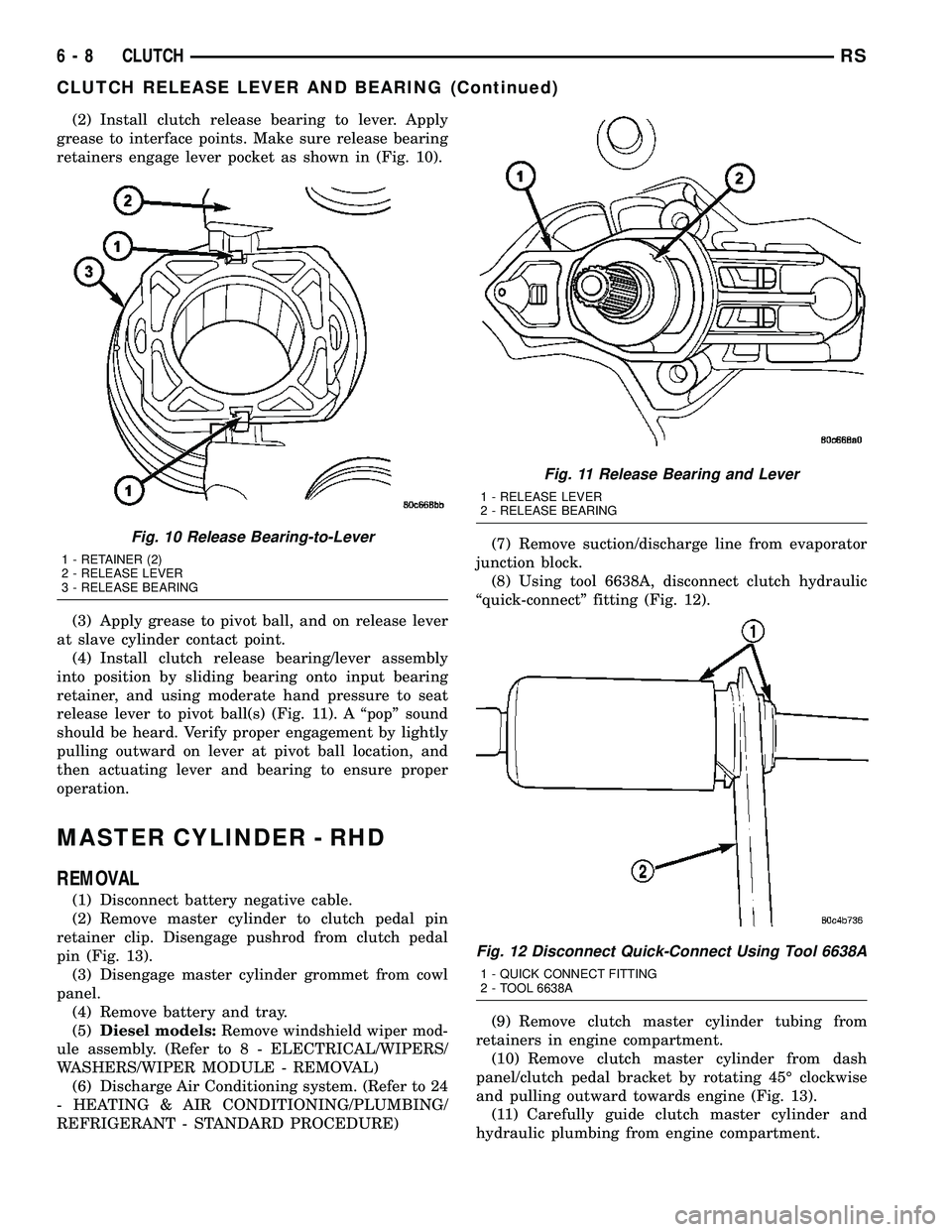
(2) Install clutch release bearing to lever. Apply
grease to interface points. Make sure release bearing
retainers engage lever pocket as shown in (Fig. 10).
(3) Apply grease to pivot ball, and on release lever
at slave cylinder contact point.
(4) Install clutch release bearing/lever assembly
into position by sliding bearing onto input bearing
retainer, and using moderate hand pressure to seat
release lever to pivot ball(s) (Fig. 11). A ªpopº sound
should be heard. Verify proper engagement by lightly
pulling outward on lever at pivot ball location, and
then actuating lever and bearing to ensure proper
operation.
MASTER CYLINDER - RHD
REMOVAL
(1) Disconnect battery negative cable.
(2) Remove master cylinder to clutch pedal pin
retainer clip. Disengage pushrod from clutch pedal
pin (Fig. 13).
(3) Disengage master cylinder grommet from cowl
panel.
(4) Remove battery and tray.
(5)Diesel models:Remove windshield wiper mod-
ule assembly. (Refer to 8 - ELECTRICAL/WIPERS/
WASHERS/WIPER MODULE - REMOVAL)
(6) Discharge Air Conditioning system. (Refer to 24
- HEATING & AIR CONDITIONING/PLUMBING/
REFRIGERANT - STANDARD PROCEDURE)(7) Remove suction/discharge line from evaporator
junction block.
(8) Using tool 6638A, disconnect clutch hydraulic
ªquick-connectº fitting (Fig. 12).
(9) Remove clutch master cylinder tubing from
retainers in engine compartment.
(10) Remove clutch master cylinder from dash
panel/clutch pedal bracket by rotating 45É clockwise
and pulling outward towards engine (Fig. 13).
(11) Carefully guide clutch master cylinder and
hydraulic plumbing from engine compartment.
Fig. 10 Release Bearing-to-Lever
1 - RETAINER (2)
2 - RELEASE LEVER
3 - RELEASE BEARING
Fig. 11 Release Bearing and Lever
1 - RELEASE LEVER
2 - RELEASE BEARING
Fig. 12 Disconnect Quick-Connect Using Tool 6638A
1 - QUICK CONNECT FITTING
2 - TOOL 6638A
6 - 8 CLUTCHRS
CLUTCH RELEASE LEVER AND BEARING (Continued)
Page 330 of 2585
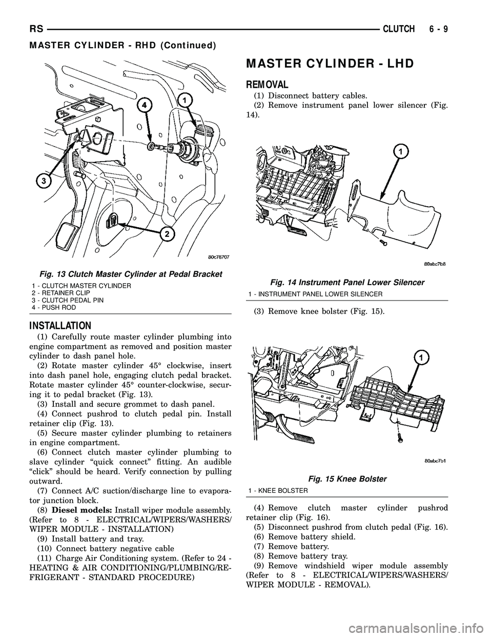
INSTALLATION
(1) Carefully route master cylinder plumbing into
engine compartment as removed and position master
cylinder to dash panel hole.
(2) Rotate master cylinder 45É clockwise, insert
into dash panel hole, engaging clutch pedal bracket.
Rotate master cylinder 45É counter-clockwise, secur-
ing it to pedal bracket (Fig. 13).
(3) Install and secure grommet to dash panel.
(4) Connect pushrod to clutch pedal pin. Install
retainer clip (Fig. 13).
(5) Secure master cylinder plumbing to retainers
in engine compartment.
(6) Connect clutch master cylinder plumbing to
slave cylinder ªquick connectº fitting. An audible
ªclickº should be heard. Verify connection by pulling
outward.
(7) Connect A/C suction/discharge line to evapora-
tor junction block.
(8)Diesel models:Install wiper module assembly.
(Refer to 8 - ELECTRICAL/WIPERS/WASHERS/
WIPER MODULE - INSTALLATION)
(9) Install battery and tray.
(10) Connect battery negative cable
(11) Charge Air Conditioning system. (Refer to 24 -
HEATING & AIR CONDITIONING/PLUMBING/RE-
FRIGERANT - STANDARD PROCEDURE)
MASTER CYLINDER - LHD
REMOVAL
(1) Disconnect battery cables.
(2) Remove instrument panel lower silencer (Fig.
14).
(3) Remove knee bolster (Fig. 15).
(4) Remove clutch master cylinder pushrod
retainer clip (Fig. 16).
(5) Disconnect pushrod from clutch pedal (Fig. 16).
(6) Remove battery shield.
(7) Remove battery.
(8) Remove battery tray.
(9) Remove windshield wiper module assembly
(Refer to 8 - ELECTRICAL/WIPERS/WASHERS/
WIPER MODULE - REMOVAL).
Fig. 13 Clutch Master Cylinder at Pedal Bracket
1 - CLUTCH MASTER CYLINDER
2 - RETAINER CLIP
3 - CLUTCH PEDAL PIN
4 - PUSH RODFig. 14 Instrument Panel Lower Silencer
1 - INSTRUMENT PANEL LOWER SILENCER
Fig. 15 Knee Bolster
1 - KNEE BOLSTER
RSCLUTCH6-9
MASTER CYLINDER - RHD (Continued)
Page 331 of 2585

(10) Using Tool 6638A, disconnect clutch master
cylinder ªquick connectº fitting (Fig. 17). Disengage
plumbing retainer from body stud.
(11) Remove master cylinder reservoir-to-strut
tower nuts (Fig. 18). Reposition reservoir off to side.
(12) Remove clutch master cylinder from dash
panel by rotating clockwise 45É and removing from
dash panel (Fig. 18).(13) Remove master cylinder and plumbing from
engine compartment. Use care not to bend or kink
plumbing. Note plumbing routing to aid in installa-
tion.
INSTALLATION
(1) Install master cylinder into position, while
routing plumbing as originally installed.
(2) Insert master cylinder pushrod through dash
panel (Fig. 18) and rotate 45É counter-clockwise to
secure.
(3) Connect master cylinder plumbing quick-con-
nect fitting. An audible ªclickº should be heard. Ver-
ify connection by pulling outward.
(4) Install master cylinder reservoir onto strut
tower. Install and tighten two (2) master cylinder
reservoir-to-strut tower nuts to 11 N´m (100 in. lbs.)
(Fig. 18).
(5) Install windshield wiper module assembly
(Refer to 8 - ELECTRICAL/WIPERS/WASHERS/
WIPER MODULE - INSTALLATION).
(6) Install battery tray.
(7) Install battery.
(8) Install battery shield.
(9) Connect master cylinder pushrod to clutch
pedal lever (Fig. 16). Install retainer clip.
(10) Install knee bolster and instrument panel
lower silencer (Fig. 15) (Fig. 14).
(11) Connect battery cables.
Fig. 16 Master Cylinder Pushrod at Pedal
1 - MASTER CYLINDER PUSHROD
2 - CLUTCH/BRAKE PEDAL ASSEMBLY
3 - PUSHROD RETAINER
Fig. 17 Disconnect Quick-Connect Using Tool 6638A
1 - QUICK CONNECT FITTING
2 - TOOL 6638A
Fig. 18 Clutch Master Cylinder Removal/Installation
1 - CLUTCH MASTER CYLINDER
2 - RESERVOIR
3 - NUT (2)
6 - 10 CLUTCHRS
MASTER CYLINDER - LHD (Continued)
Page 351 of 2585
ENGINE
DIAGNOSIS AND TESTING - ENGINE COOLING
SYSTEM
Establish what driving condition caused the cooling
system complaint. The problem may be caused by an
abnormal load on the system such as the following:
prolonged idle, very high ambient temperature, slight
tail wind at idle, slow traffic speed, traffic jam, high
speed, steep grade.
DRIVING TECHNIQUES
To avoid overheating the cooling system:
(1) Idle with A/C off when temperature gauge is at
end of normal range.
(2) Do not increase engine speed for more air flow
and coolant flow because the electric motor fan sys-
tems are not responsive to engine RPM. The added
cooling from higher coolant flow rate is more than
offset by increased heat rejection (engine heat added
to coolant).
TRAILER TOWING
Consult the owner's manual under Trailer Towing
and do not exceed specified limits.
VISUAL INSPECTION
If the cooling system problem is not caused by a
driving condition, perform a visual inspection to
determine if there was a recent service or accident
repair, including the following:
²Loose/damaged water pump drive belt
²Incorrect cooling system refilling (trapped air or
low level)
²Brakes possibly dragging
²Damaged hoses
²Loose/damaged hose clamps
²Damaged/incorrect engine thermostat
²Damaged cooling fan motor, fan blade and fan
shroud
²Damaged head gasket
²Damaged water pump
²Damaged radiator
²Damaged coolant recovery system
²Damaged heater core
²Open/shorted electrical circuits
If the visual inspection reveals none of the above
as cause for a cooling system complaint, refer to the
following diagnostic charts.
COOLING SYSTEM DIAGNOSIS CHART
CONDITION POSSIBLE CAUSES CORRECTION
PRESSURE CAP IS BLOWING
OFF STEAM AND/OR COOLANT.
TEMPERATURE GAUGE READING
MAY BE ABOVE NORMAL BUT
NOT HIGH. COOLANT LEVEL MAY
BE HIGH IN COOLANT RESERVE/
OVERFLOW TANK.1. Pressure relief valve in radiator
cap is defective, or was not
properly seated.1. Check condition of radiator cap
and cap seal. (Refer to 7 -
COOLING/ENGINE/RADIATOR
PRESSURE CAP - DIAGNOSIS
AND TESTING) Replace cap as
necessary.
2. Incorrect cap was installed. 2. Replace cap as necessary.
3. Incorrect coolant mixture. 3. Check concentration level of the
coolant. (Refer to 7 - COOLING/
ENGINE/COOLANT - DIAGNOSIS
AND TESTING) Adjust the ethylene
glycol-to-water ratio as required.
COOLANT LOSS TO THE
GROUND WITHOUT PRESSURE
CAP BLOWOFF. GAUGE IS
READING HIGH OR HOT.1. Coolant leaks in radiator, cooling
system hoses, water pump or
engine.1. Pressure test and repair as
necessary. (Refer to 7 - COOLING -
DIAGNOSIS AND TESTING)
7 - 14 ENGINERS