service indicator CHRYSLER VOYAGER 2004 Owner's Manual
[x] Cancel search | Manufacturer: CHRYSLER, Model Year: 2004, Model line: VOYAGER, Model: CHRYSLER VOYAGER 2004Pages: 2585, PDF Size: 62.54 MB
Page 1800 of 2585
STANDARD PROCEDURE - FLUID AND FILTER
SERVICE
NOTE: Refer to the maintenance schedules in
LUBRICATION and MAINTENANCE, or the vehicle
owner's manual, for the recommended maintenance
(fluid/filter change) intervals for this transaxle.
NOTE: Only fluids of the type labeled MoparTATF+4
(Automatic Transmission Fluid) should be used. A
filter change should be made at the time of the
transmission oil change. The magnet (on the inside
of the oil pan) should also be cleaned with a clean,
dry cloth.
NOTE: If the transaxle is disassembled for any rea-
son, the fluid and filter should be changed.
FLUID/FILTER SERVICE (RECOMMENDED)
(1) Raise vehicle on a hoist. Refer to LUBRICA-
TION and MAINTENANCE for proper procedures.
Place a drain container with a large opening, under
transaxle oil pan.
(2) Loosen pan bolts and tap the pan at one corner
to break it loose allowing fluid to drain, then remove
the oil pan.
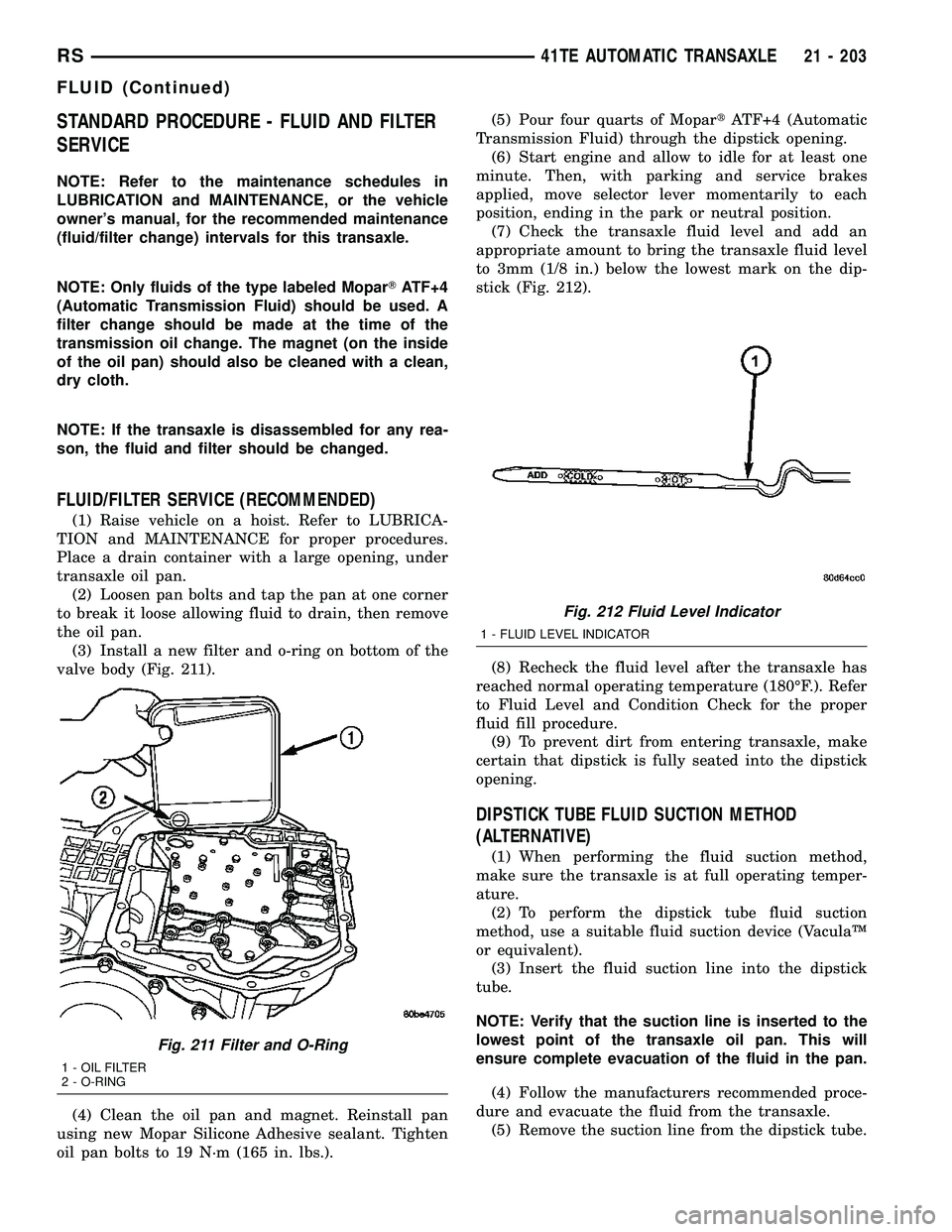
(3) Install a new filter and o-ring on bottom of the
valve body (Fig. 211).
(4) Clean the oil pan and magnet. Reinstall pan
using new Mopar Silicone Adhesive sealant. Tighten
oil pan bolts to 19 N´m (165 in. lbs.).(5) Pour four quarts of MopartATF+4 (Automatic
Transmission Fluid) through the dipstick opening.
(6) Start engine and allow to idle for at least one
minute. Then, with parking and service brakes
applied, move selector lever momentarily to each
position, ending in the park or neutral position.
(7) Check the transaxle fluid level and add an
appropriate amount to bring the transaxle fluid level
to 3mm (1/8 in.) below the lowest mark on the dip-
stick (Fig. 212).
(8) Recheck the fluid level after the transaxle has
reached normal operating temperature (180ÉF.). Refer
to Fluid Level and Condition Check for the proper
fluid fill procedure.
(9) To prevent dirt from entering transaxle, make
certain that dipstick is fully seated into the dipstick
opening.
DIPSTICK TUBE FLUID SUCTION METHOD
(ALTERNATIVE)
(1) When performing the fluid suction method,
make sure the transaxle is at full operating temper-
ature.
(2) To perform the dipstick tube fluid suction
method, use a suitable fluid suction device (VaculaŸ
or equivalent).
(3) Insert the fluid suction line into the dipstick
tube.
NOTE: Verify that the suction line is inserted to the
lowest point of the transaxle oil pan. This will
ensure complete evacuation of the fluid in the pan.
(4) Follow the manufacturers recommended proce-
dure and evacuate the fluid from the transaxle.
(5) Remove the suction line from the dipstick tube.
Fig. 211 Filter and O-Ring
1 - OIL FILTER
2 - O-RING
Fig. 212 Fluid Level Indicator
1 - FLUID LEVEL INDICATOR
RS41TE AUTOMATIC TRANSAXLE21 - 203
FLUID (Continued)
Page 1893 of 2585
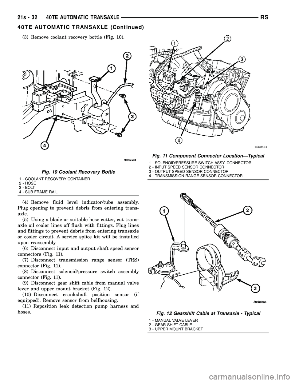
(3) Remove coolant recovery bottle (Fig. 10).
(4) Remove fluid level indicator/tube assembly.
Plug opening to prevent debris from entering trans-
axle. (5) Using a blade or suitable hose cutter, cut trans-
axle oil cooler lines off flush with fittings. Plug lines
and fittings to prevent debris from entering transaxle
or cooler circuit. A service splice kit will be installed
upon reassembly. (6) Disconnect input and output shaft speed sensor
connectors (Fig. 11). (7) Disconnect transmission range sensor (TRS)
connector (Fig. 11). (8) Disconnect solenoid/pressure switch assembly
connector (Fig. 11). (9) Disconnect gear shift cable from manual valve
lever and upper mount bracket (Fig. 12). (10) Disconnect crankshaft position sensor (if
equipped). Remove sensor from bellhousing. (11) Reposition leak detection pump harness and
hoses.
Fig. 10 Coolant Recovery Bottle
1 - COOLANT RECOVERY CONTAINER
2 - HOSE
3 - BOLT
4 - SUB FRAME RAIL
Fig. 11 Component Connector LocationÐTypical
1 - SOLENOID/PRESSURE SWITCH ASSY. CONNECTOR
2 - INPUT SPEED SENSOR CONNECTOR
3 - OUTPUT SPEED SENSOR CONNECTOR
4 - TRANSMISSION RANGE SENSOR CONNECTOR
Fig. 12 Gearshift Cable at Transaxle - Typical
1 - MANUAL VALVE LEVER
2 - GEAR SHIFT CABLE
3 - UPPER MOUNT BRACKET
21s - 32 40TE AUTOMATIC TRANSAXLERS
40TE AUTOMATIC TRANSAXLE (Continued)
Page 1927 of 2585
NOTE: The 2/4 Clutch Piston has bonded seals
which are not individually serviceable. Seal replace-
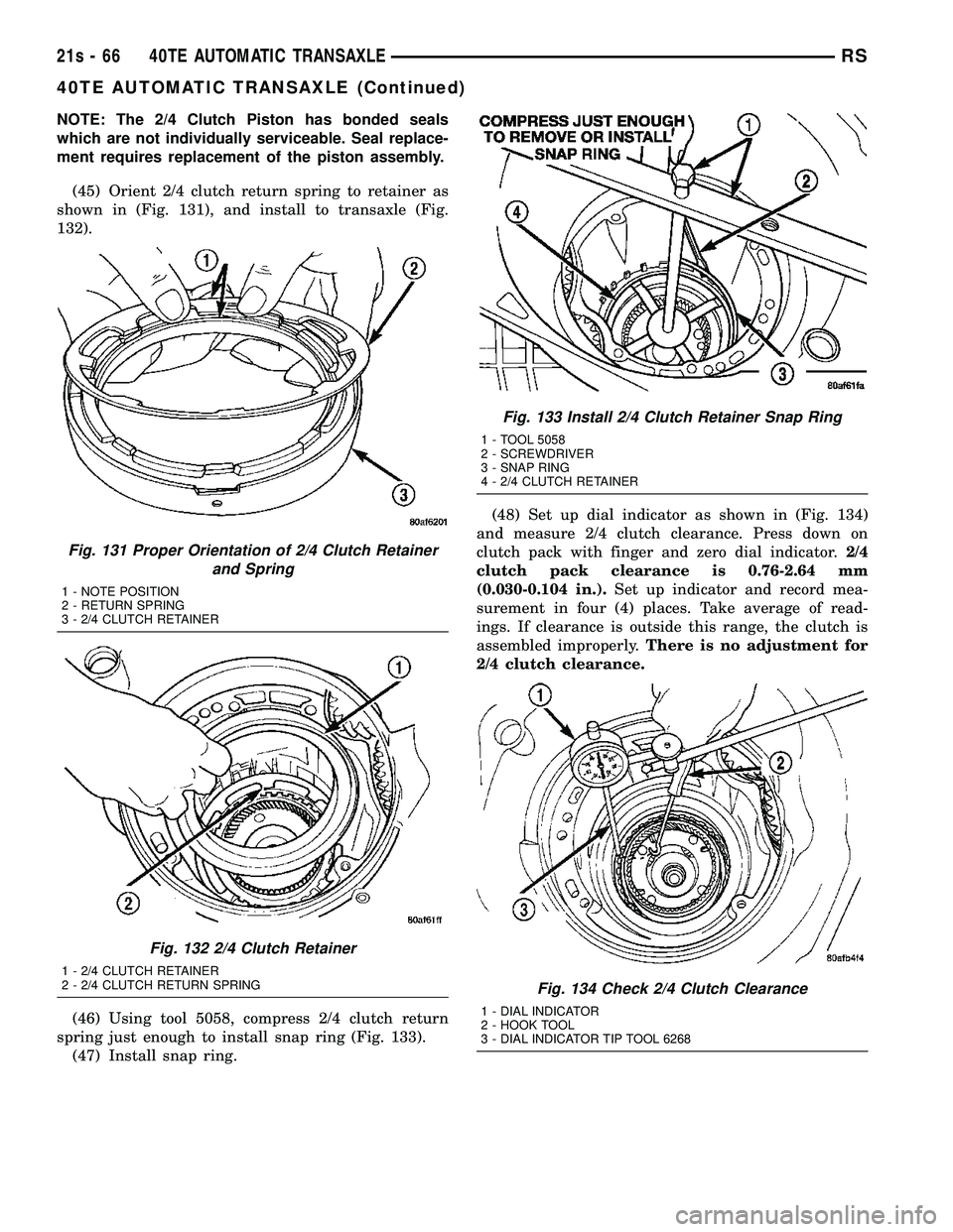
ment requires replacement of the piston assembly.(45) Orient 2/4 clutch return spring to retainer as
shown in (Fig. 131), and install to transaxle (Fig.
132).
(46) Using tool 5058, compress 2/4 clutch return
spring just enough to install snap ring (Fig. 133). (47) Install snap ring. (48) Set up dial indicator as shown in (Fig. 134)
and measure 2/4 clutch clearance. Press down on
clutch pack with finger and zero dial indicator. 2/4
clutch pack clearance is 0.76-2.64 mm
(0.030-0.104 in.). Set up indicator and record mea-
surement in four (4) places. Take average of read-
ings. If clearance is outside this range, the clutch is
assembled improperly. There is no adjustment for
2/4 clutch clearance.
Fig. 131 Proper Orientation of 2/4 Clutch Retainer and Spring
1 - NOTE POSITION
2 - RETURN SPRING
3 - 2/4 CLUTCH RETAINER
Fig. 132 2/4 Clutch Retainer
1 - 2/4 CLUTCH RETAINER
2 - 2/4 CLUTCH RETURN SPRING
Fig. 133 Install 2/4 Clutch Retainer Snap Ring
1 - TOOL 5058
2 - SCREWDRIVER
3 - SNAP RING
4 - 2/4 CLUTCH RETAINER
Fig. 134 Check 2/4 Clutch Clearance
1 - DIAL INDICATOR
2 - HOOK TOOL
3 - DIAL INDICATOR TIP TOOL 6268
21s - 66 40TE AUTOMATIC TRANSAXLERS
40TE AUTOMATIC TRANSAXLE (Continued)
Page 1935 of 2585
(13) Install left and right halfshaft assemblies.
(Refer t o 3 - DIFFERENTIAL & DRIVELINE/HALF
SHAFT - INSTALLATION) (14) Install front wheel/tire assemblies.
(15) Lower vehicle.
(16) Torque remaining rear mount bracket-to-tran-
saxle vertical bolts (Fig. 160) to 102 N´m (75 ft. lbs.). (17) Install transaxle upper bellhousing-to-block
bolts and torque to 95 N´m (70 ft. lbs.). (18) Install and connect crank position sensor (if
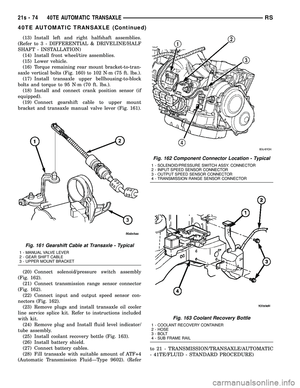
equipped). (19) Connect gearshift cable to upper mount
bracket and transaxle manual valve lever (Fig. 161).
(20) Connect solenoid/pressure switch assembly
(Fig. 162). (21) Connect transmission range sensor connector
(Fig. 162). (22) Connect input and output speed sensor con-
nectors (Fig. 162). (23) Remove plugs and install transaxle oil cooler
line service splice kit. Refer to instructions included
with kit. (24) Remove plug and Install fluid level indicator/
tube assembly. (25) Install coolant recovery bottle (Fig. 163).
(26) Install battery shield.
(27) Connect battery cables.
(28) Fill transaxle with suitable amount of ATF+4
(Automatic Transmission FluidÐType 9602). (Refer to 21 - TRANSMISSION/TRANSAXLE/AUTOMATIC
- 41TE/FLUID - STANDARD PROCEDURE)
Fig. 161 Gearshift Cable at Transaxle - Typical
1 - MANUAL VALVE LEVER
2 - GEAR SHIFT CABLE
3 - UPPER MOUNT BRACKET
Fig. 162 Component Connector Location - Typical
1 - SOLENOID/PRESSURE SWITCH ASSY. CONNECTOR
2 - INPUT SPEED SENSOR CONNECTOR
3 - OUTPUT SPEED SENSOR CONNECTOR
4 - TRANSMISSION RANGE SENSOR CONNECTOR
Fig. 163 Coolant Recovery Bottle
1 - COOLANT RECOVERY CONTAINER
2 - HOSE
3 - BOLT
4 - SUB FRAME RAIL
21s - 74 40TE AUTOMATIC TRANSAXLERS
40TE AUTOMATIC TRANSAXLE (Continued)
Page 1965 of 2585
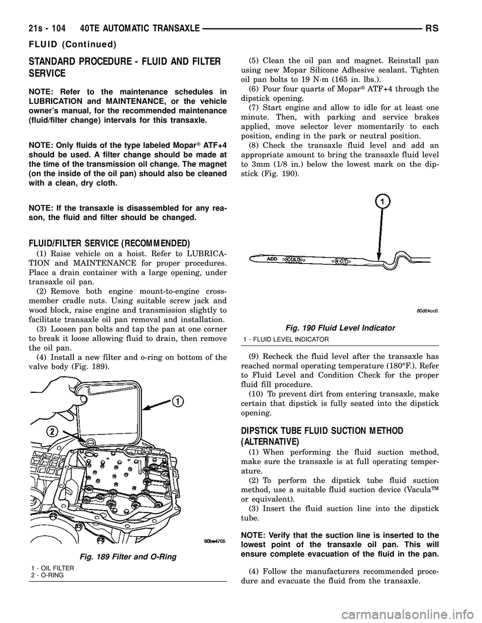
STANDARD PROCEDURE - FLUID AND FILTER
SERVICE
NOTE: Refer to the maintenance schedules in
LUBRICATION and MAINTENANCE, or the vehicle
owner's manual, for the recommended maintenance
(fluid/filter change) intervals for this transaxle.
NOTE: Only fluids of the type labeled MoparTATF+4
should be used. A filter change should be made at
the time of the transmission oil change. The magnet
(on the inside of the oil pan) should also be cleaned
with a clean, dry cloth.
NOTE: If the transaxle is disassembled for any rea-
son, the fluid and filter should be changed.
FLUID/FILTER SERVICE (RECOMMENDED)
(1) Raise vehicle on a hoist. Refer to LUBRICA-
TION and MAINTENANCE for proper procedures.
Place a drain container with a large opening, under
transaxle oil pan. (2) Remove both engine mount-to-engine cross-
member cradle nuts. Using suitable screw jack and
wood block, raise engine and transmission slightly to
facilitate transaxle oil pan removal and installation. (3) Loosen pan bolts and tap the pan at one corner
to break it loose allowing fluid to drain, then remove
the oil pan. (4) Install a new filter and o-ring on bottom of the
valve body (Fig. 189). (5) Clean the oil pan and magnet. Reinstall pan
using new Mopar Silicone Adhesive sealant. Tighten
oil pan bolts to 19 N´m (165 in. lbs.). (6) Pour four quarts of Mopar tATF+4 through the
dipstick opening. (7) Start engine and allow to idle for at least one
minute. Then, with parking and service brakes
applied, move selector lever momentarily to each
position, ending in the park or neutral position. (8) Check the transaxle fluid level and add an
appropriate amount to bring the transaxle fluid level
to 3mm (1/8 in.) below the lowest mark on the dip-
stick (Fig. 190).
(9) Recheck the fluid level after the transaxle has
reached normal operating temperature (180ÉF.). Refer
to Fluid Level and Condition Check for the proper
fluid fill procedure. (10) To prevent dirt from entering transaxle, make
certain that dipstick is fully seated into the dipstick
opening.
DIPSTICK TUBE FLUID SUCTION METHOD
(ALTERNATIVE)
(1) When performing the fluid suction method,
make sure the transaxle is at full operating temper-
ature. (2) To perform the dipstick tube fluid suction
method, use a suitable fluid suction device (VaculaŸ
or equivalent). (3) Insert the fluid suction line into the dipstick
tube.
NOTE: Verify that the suction line is inserted to the
lowest point of the transaxle oil pan. This will
ensure complete evacuation of the fluid in the pan.
(4) Follow the manufacturers recommended proce-
dure and evacuate the fluid from the transaxle.
Fig. 189 Filter and O-Ring
1 - OIL FILTER
2 - O-RING
Fig. 190 Fluid Level Indicator
1 - FLUID LEVEL INDICATOR
21s - 104 40TE AUTOMATIC TRANSAXLERS
FLUID (Continued)
Page 2059 of 2585
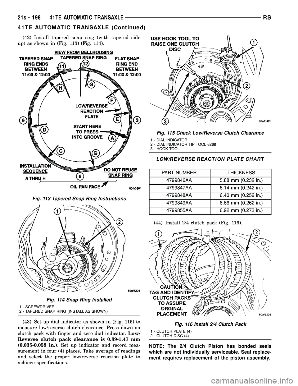
(42) Install tapered snap ring (with tapered side
up) as shown in (Fig. 113) (Fig. 114).
(43) Set up dial indicator as shown in (Fig. 115) to
measure low/reverse clutch clearance. Press down on
clutch pack with finger and zero dial indicator. Low/
Reverse clutch pack clearance is 0.89-1.47 mm
(0.035-0.058 in.) . Set up indicator and record mea-
surement in four (4) places. Take average of readings
and select the proper low/reverse reaction plate to
achieve specifications.
LOW/REVERSE REACTION PLATE CHART
PART NUMBER THICKNESS
4799846AA 5.88 mm (0.232 in.)
4799847AA 6.14 mm (0.242 in.)
4799848AA 6.40 mm (0.252 in.)
4799849AA 6.66 mm (0.262 in.)
4799855AA 6.92 mm (0.273 in.)
(44) Install 2/4 clutch pack (Fig. 116).
NOTE: The 2/4 Clutch Piston has bonded seals
which are not individually serviceable. Seal replace-
ment requires replacement of the piston assembly.
Fig. 113 Tapered Snap Ring Instructions
Fig. 114 Snap Ring Installed
1 - SCREWDRIVER
2 - TAPERED SNAP RING (INSTALL AS SHOWN)
Fig. 115 Check Low/Reverse Clutch Clearance
1 - DIAL INDICATOR
2 - DIAL INDICATOR TIP TOOL 6268
3 - HOOK TOOL
Fig. 116 Install 2/4 Clutch Pack
1 - CLUTCH PLATE (4)
2 - CLUTCH DISC (4)
21s - 198 41TE AUTOMATIC TRANSAXLERS
41TE AUTOMATIC TRANSAXLE (Continued)
Page 2580 of 2585
TRANSMITTER CODES - STANDARD
PROCEDURE, SETTING................8M-11
TRANSMITTER PROGRAMING -
STANDARD PROCEDURE, RKE..........8N-43
TRANSMITTER PROGRAMMING -
STANDARD PROCEDURE, REMOTE
KEYLESS ENTRY......................8N-5
TRANSMITTER RANGE -
SPECIFICATIONS......................8N-5
TRANSPONDER KEY - DESCRIPTION......8Q-6
TRANSPONDER KEY - OPERATION........8Q-6
TRANSPONDER PROGRAMMING -
STANDARD PROCEDURE...............8Q-6
TRANSVERSE BRACKET - DESCRIPTION . . 8N-18
TRANSVERSE BRACKET - INSTALLATION . . 8N-18
TRANSVERSE BRACKET - OPERATION....8N-18
TRANSVERSE BRACKET - REMOVAL.....8N-18
TRAY - BRACKET ASSEMBLY -
INSTALLATION, FLOOR CONSOLE........23-83
TRAY - BRACKET ASSEMBLY -
REMOVAL, FLOOR CONSOLE...........23-83
TRAY - DESCRIPTION, BATTERY.........8F-18
TRAY - INSTALLATION, BATTERY........8F-19
TRAY - INSTALLATION, FLOOR CONSOLE . . 23-83
TRAY - OPERATION, BATTERY......8F-18,8F-19
TRAY - REMOVAL, BATTERY............8F-19
TRAY - REMOVAL, FLOOR CONSOLE.....23-83
TRD LINK - DESCRIPTION............21-249
TRD LINK - OPERATION..............21-249
TREAD WEAR INDICATORS - DIAGNOSIS
AND TESTING..................22-16,22s-8
TRIM - INSTALLATION, A-PILLAR........23-74
TRIM - INSTALLATION, A-PILLAR
LOWER EXTENSION..................23-74
TRIM - INSTALLATION, B-PILLAR
LOWER............................23-75
TRIM - INSTALLATION, B-PILLAR UPPER . . 23-75
TRIM - INSTALLATION, COWL..........23-76
TRIM - INSTALLATION, C-PILLAR........23-77
TRIM - INSTALLATION, REAR HEADER....23-80
TRIM - REMOVAL, A-PILLAR...........23-74
TRIM - REMOVAL, A-PILLAR LOWER
EXTENSION.........................23-74
TRIM - REMOVAL, B-PILLAR LOWER.....23-74
TRIM - REMOVAL, B-PILLAR UPPER.....23-75
TRIM - REMOVAL, COWL..............23-76
TRIM - REMOVAL, C-PILLAR...........23-77
TRIM - REMOVAL, REAR HEADER.......23-80
TRIM BOLSTER - INSTALLATION,
QUARTER..........................23-79
TRIM BOLSTER - REMOVAL, QUARTER . . . 23-79
TRIM COVER - INSTALLATION, DRIVER
AIRBAG.............................8O-7
TRIM COVER - REMOVAL, DRIVER
AIRBAG.............................8O-7
TRIM PANEL - INSTALLATION.....23-20,23-34,
23-44
TRIM PANEL - INSTALLATION, LEFT
D-PILLAR...........................23-78
TRIM PANEL - INSTALLATION, LEFT
QUARTER..........................23-80
TRIM PANEL - INSTALLATION, RIGHT
D-PILLAR...........................23-82
TRIM PANEL - INSTALLATION, RIGHT
QUARTER..........................23-79
TRIM PANEL - REMOVAL....23-20,23-33,23-43
TRIM PANEL - REMOVAL, LEFT
D-PILLAR...........................23-78
TRIM PANEL - REMOVAL, LEFT
QUARTER..........................23-80
TRIM PANEL - REMOVAL, RIGHT
D-PILLAR...........................23-81
TRIM PANEL - REMOVAL, RIGHT
QUARTER..........................23-79
TRIM PLATE - INSTALLATION, DOOR
SILL...............................23-77
TRIM PLATE - REMOVAL, DOOR SILL....23-77
TRIP DEFINITION - DESCRIPTION.........25-1
TROUBLE CODES - STANDARD
PROCEDURE, OBTAINING DIAGNOSTIC
. . . 8E-15
TUBE - 2.4L - DESCRIPTION, WATER
PUMP INLET
.........................7-35
TUBE - 2.4L - INSTALLATION, WATER
PUMP INLET
.........................7-35
TUBE - 2.4L - REMOVAL, WATER PUMP
INLET
...............................7-35
TUBE - 3.3/3.8L - INSTALLATION, WATER
PUMP INLET
.........................7-36TUBE - 3.3/3.8L - REMOVAL, WATER
PUMP INLET.........................7-36
TUBE - INSTALLATION, DRAIN.........23-120
TUBE - INSTALLATION, EXHAUST.......24-115
TUBE - INSTALLATION, FUEL TANK
FILLER.............................14-13
TUBE - REMOVAL, DRAIN.............23-119
TUBE - REMOVAL, EXHAUST..........24-114
TUBE - REMOVAL, FUEL TANK FILLER....14-12
TUBES - INSTALLATION, HEATER CORE . . . 24-85
TUBES - REMOVAL, HEATER CORE.......24-83
TUBES - REMOVAL, UNDERBODY
HEATER ...........................24-109
TUBES AND HOSES - DESCRIPTION,
BRAKE.........................5-14,5s-13
TUBES AND HOSES - INSPECTION,
BRAKE.........................5-14,5s-13
TUBES AND HOSES - OPERATION,
BRAKE.........................5-14,5s-13
TUBING AND FITTINGS - STANDARD
PROCEDURE, HANDLING..............24-70
TURN SIGNAL SYSTEM - DESCRIPTION . . . 8L-17
TURN SIGNAL SYSTEM - OPERATION....8L-18
TURNING TORQUE - ADJUSTMENT,
DIFFERENTIAL.......................21-69
UNDER SEAT STORAGE BIN -
INSTALLATION......................23-105
UNDER SEAT STORAGE BIN - REMOVAL . 23-105
UNDER SEAT STORAGE BIN GUIDE -
INSTALLATION......................23-105
UNDER SEAT STORAGE BIN GUIDE -
REMOVAL.........................23-105
UNDER SEAT STORAGE BIN LOCK/LATCH
- INSTALLATION....................23-105
UNDER SEAT STORAGE BIN LOCK/LATCH
- REMOVAL........................23-105
UNDERBODY HEATER TUBES -
REMOVAL.........................24-109
UNDERBODY LINES - DESCRIPTION.....24-107
UNDERBODY LINES - OPERATION......24-107
UNDERBODY REFRIGERANT LINES -
INSTALLATION......................24-111
UNDERBODY REFRIGERANT LINES -
REMOVAL.........................24-110
UNIT - DESCRIPTION, LOWER DRIVE....8N-32
UNIT - DESCRIPTION, POWER
TRANSFER...........................21-1
UNIT - EXPORT - INSTALLATION,
HEADLAMP.........................8L-17
UNIT - EXPORT - REMOVAL, HEADLAMP . . 8L-17
UNIT - INSTALLATION, CENTER HIGH
MOUNTED STOP LAMP.................8L-6
UNIT - INSTALLATION, HEATER........24-119
UNIT - INSTALLATION, LOWER DRIVE....8N-33
UNIT - INSTALLATION, TAIL LAMP.......8L-19
UNIT - OPERATION, LOWER DRIVE......8N-32
UNIT - OPERATION, POWER TRANSFER....21-3
UNIT - REMOVAL, CENTER HIGH
MOUNTED STOP LAMP.................8L-6
UNIT - REMOVAL, HEATER............24-118
UNIT - REMOVAL, LOWER DRIVE.......8N-33
UNIT - REMOVAL, TAIL LAMP
...........8L-19
UNIT / SENSOR - DESCRIPTION, FUEL
LEVEL SENDING
......................14-5
UNIT / SENSOR - INSTALLATION, FUEL
LEVEL SENDING
......................14-5
UNIT / SENSOR - OPERATION, FUEL
LEVEL SENDING
......................14-5
UNIT / SENSOR - REMOVAL, FUEL
LEVEL SENDING
......................14-5
UNIT ALIGNMENT - EXPORT -
STANDARD PROCEDURE, FRONT FOG
LAMP
...............................8L-9
UNIT ALIGNMENT - EXPORT -
STANDARD PROCEDURE, HEADLAMP
....8L-14
UNIT ALIGNMENT - STANDARD
PROCEDURE, FRONT FOG LAMP
.........8L-9
UNIT ALIGNMENT - STANDARD
PROCEDURE, HEADLAMP
..............8L-13
UNIT FLUID - DESCRIPTION, AWD
POWER TRANSFER
.....................0-6
UNIT, SPECIAL TOOLS - SDP POWER
TRANSFER
...........................21-8
UNIT TRACK & RACK - DESCRIPTION,
LOWER DRIVE
......................8N-34
UNIT TRACK & RACK - INSTALLATION,
LOWER DRIVE
......................8N-34UNIT TRACK & RACK - OPERATION,
LOWER DRIVE......................8N-34
UNIT TRACK & RACK - REMOVAL,
LOWER DRIVE......................8N-34
UNIVERSAL TRANSMITTER -
DESCRIPTION.......................8M-10
UNIVERSAL TRANSMITTER - DIAGNOSIS
AND TESTING.......................8M-10
UNIVERSAL TRANSMITTER - OPERATION . 8M-10
UPPER - INSPECTION, INTAKE
MANIFOLD...........................9-59
UPPER - INSTALLATION, INTAKE
MANIFOLD...........................9-59
UPPER - INSTALLATION, SHROUD.......19-23
UPPER - REMOVAL, INTAKE MANIFOLD....9-58
UPPER - REMOVAL, SHROUD...........19-23
UPPER HINGE - INSTALLATION.........23-36
UPPER HINGE - REMOVAL.............23-36
UPPER INTAKE MANIFOLD -
INSTALLATION.......................9-147
UPPER INTAKE MANIFOLD - REMOVAL . . . 9-145
UPPER TRIM - INSTALLATION, B-PILLAR . . 23-75
UPPER TRIM - REMOVAL, B-PILLAR.....23-75
UPSTOP SWITCH - INSTALLATION,
CLUTCH PEDAL.......................6-16
UPSTOP SWITCH - REMOVAL, CLUTCH
PEDAL..............................6-15
UPSTREAM 1/1 - 2.4L - INSTALLATION . . . 14-34
UPSTREAM 1/1 - 2.4L - REMOVAL.......14-33
UPSTREAM 1/1 - 3.3/3.8L -
INSTALLATION.......................14-34
UPSTREAM 1/1 - 3.3/3.8L - REMOVAL....14-33
USAGE - DESCRIPTION, FASTENER.....Intro.-5
USE WIRING DIAGRAMS -
DESCRIPTION, HOW TO.............8W-01-1
USING PLASTIGAGE - STANDARD
PROCEDURE, MEASURING BEARING
CLEARANCE.....................9-12,9-84
VAC LEAK DETECTION ASSY -
INSTALLATION, NATURAL..............25-13
VAC LEAK DETECTION ASSY -
REMOVAL, NATURAL..................25-13
VACUUM PORT REPAIR - STANDARD
PROCEDURE, INTAKE MANIFOLD........9-145
VACUUM RESERVOIR - DESCRIPTION.....8P-6
VACUUM RESERVOIR - INSTALLATION....8P-6
VACUUM RESERVOIR - OPERATION.......8P-6
VACUUM RESERVOIR - REMOVAL........8P-6
VALVE - DESCRIPTION................25-22
VALVE - DESCRIPTION, A/C EXPANSION . . 24-99
VALVE - DESCRIPTION, EXPANSION......24-81
VALVE - DESCRIPTION, HIGH PRESSURE
RELIEF.............................24-73
VALVE - DESCRIPTION, PCV............25-16
VALVE - DIAGNOSIS AND TESTING, A/C
EXPANSION.........................24-81
VALVE - DIAGNOSIS AND TESTING,
EXPANSION........................24-100
VALVE - INSTALLATION, A/C EXPANSION . 24-100
VALVE - INSTALLATION, EXPANSION.....24-82
VALVE - INSTALLATION, OIL PRESSURE
RELIEF.............................9-141
VALVE - OPERATION..................25-22
VALVE - OPERATION, A/C EXPANSION....24-99
VALVE - OPERATION, EXPANSION.......24-81
VALVE - OPERATION, HIGH PRESSURE
RELIEF.............................24-73
VALVE - OPERATION, PCV..............25-16
VALVE - REMOVAL, A/C EXPANSION.....24-100
VALVE - REMOVAL, EXPANSION.........24-82
VALVE - REMOVAL, OIL PRESSURE
RELIEF.............................9-141
VALVE BODY - ASSEMBLY.....21-257,21s-159,
21s-212
VALVE BODY - DESCRIPTION . . . 21-250,21s-152
VALVE BODY - DISASSEMBLY . . 21-252,21s-155,
21s-208
VALVE BODY - INSTALLATION . . 21-262,21s-164,
21s-217
VALVE BODY - OPERATION
.....21-250,21s-152
VALVE BODY - REMOVAL
......21-251,21s-153,
21s-206
VALVE CORE - DESCRIPTION, SERVICE
PORT
..............................24-94
VALVE CORE - INSTALLATION, SERVICE
PORT
..............................24-94
VALVE CORE - REMOVAL, SERVICE
PORT
..............................24-94
RSINDEX37
Description Group-Page Description Group-Page Description Group-Page