8e electrical control module CHRYSLER VOYAGER 2004 Owner's Guide
[x] Cancel search | Manufacturer: CHRYSLER, Model Year: 2004, Model line: VOYAGER, Model: CHRYSLER VOYAGER 2004Pages: 2585, PDF Size: 62.54 MB
Page 441 of 2585
CHARGING
TABLE OF CONTENTS
page page
CHARGING
DESCRIPTION - CHARGING SYSTEM.......20
OPERATION - CHARGING SYSTEM.........20
DIAGNOSIS AND TESTING - ON-BOARD
DIAGNOSTIC SYSTEM.................21
SPECIFICATIONS
GENERATOR........................22
TORQUE............................22
SPECIFICATIONS - BATTERY
TEMPERATURE SENSOR...............22
SPECIAL TOOLS.......................23
BATTERY TEMPERATURE SENSOR
DESCRIPTION.........................23
OPERATION...........................23
REMOVAL.............................23
GENERATOR
DESCRIPTION.........................23OPERATION...........................23
REMOVAL
REMOVAL - 2.4L......................23
REMOVAL - 3.3/3.8L...................24
INSTALLATION
INSTALLATION - 2.4L..................24
INSTALLATION - 3.3/3.8L................24
GENERATOR DECOUPLER PULLEY
DESCRIPTION.........................25
OPERATION...........................25
DIAGNOSIS AND TESTING - GENERATOR
DECOUPLER PULLEY..................25
REMOVAL.............................26
INSTALLATION.........................26
VOLTAGE REGULATOR
DESCRIPTION.........................27
OPERATION...........................27
CHARGING
DESCRIPTION - CHARGING SYSTEM
The charging system consists of:
²Generator
²Decoupler Pulley (If equipped)
²Electronic Voltage Regulator (EVR) circuitry
within the Powertrain Control Module (PCM)
²Ignition switch (refer to the Ignition System sec-
tion for information)
²Battery (refer to the Battery section for informa-
tion)
²Ambient Air Temperature (If equipped)
²Inlet Air Temperature (calculated battery tem-
perature)(If equipped)
²Voltmeter (refer to the Instrument Cluster sec-
tion for information if equipped)
²Wiring harness and connections (refer to the
Wiring section for information)
²Accessory drive belt (refer to the Cooling section
for more information)
²Battery Temperature sensor (if equipped)
OPERATION - CHARGING SYSTEM
The charging system is turned on and off with the
ignition switch. The system is on when the engine is
running and the ASD relay is energized. The ASD
relay is energized when the PCM grounds the ASD
control circuit. (SBEC vehicles) This voltage is con-
nected through the PCM or IPM (intelligent powermodule) (if equipped) and supplied to one of the gen-
erator field terminals (Gen. Source +) at the back of
the generator.
The generator is driven by the engine through a
serpentine belt and pulley or decoupler pulley
arrangement.
The amount of DC current produced by the gener-
ator is controlled by the EVR (field control) circuitry
contained within the PCM. This circuitry is con-
nected in series with the second rotor field terminal
and ground.
(SBEC vehicles) An Inlet air temperature sensor is
used to calculate the temperature near the battery.
This temperature data, along with data from moni-
tored line voltage (battery voltage sense circuit), is
used by the PCM to vary the battery charging rate.
This is done by cycling the ground path to control the
strength of the rotor magnetic field. The PCM then
compensates and regulates generator current output
accordingly to maintain system voltage at the tar-
geted system voltage based on battery temperature.
All vehicles are equipped with On-Board Diagnos-
tics (OBD). All OBD-sensed systems, including EVR
(field control) circuitry, are monitored by the PCM.
Each monitored circuit is assigned a Diagnostic Trou-
ble Code (DTC). The PCM will store a DTC in elec-
tronic memory for certain failures it detects and
illuminate the (MIL) lamp. Refer to On-Board Diag-
nostics in the Electronic Control Modules(Refer to 8 -
ELECTRICAL/ELECTRONIC CONTROL MOD-
8F - 20 CHARGINGRS
Page 442 of 2585
ULES/POWERTRAIN CONTROL MODULE -
DESCRIPTION) section for more DTC information.
The Check Gauges Lamp (if equipped) or Battery
Lamp monitors:charging system voltage,engine
coolant temperature and engine oil pressure. If an
extreme condition is indicated, the lamp will be illu-
minated. The signal to activate the lamp is sent via
the PCI bus circuits. The lamp is located on the
instrument panel. Refer to the Instrument Cluster
section for additional information.
(If equipped with inlet air temperature sensor) The
PCM uses the inlet air temperature sensor to control
the charge system voltage. This temperature, along
with data from monitored line voltage, is used by the
PCM to vary the battery charging rate. The system
voltage is higher at cold temperatures and is gradu-
ally reduced as the calculated battery temperature
increases.
The ambient temperature sensor is used to control
the battery voltage based upon ambient temperature
(approximation of battery temperature). The PCM
maintains the optimal output of the generator by
monitoring battery voltage and controlling it to a
range of 13.5 - 14.7 volts based on battery tempera-
ture. The system target voltage is 13.5 ± 14.7 volts.
However the actual voltage go below this during
heavy electrical loads and generator speeds. Also the
actual voltage can be lower than the target voltage
between the battery and the battery voltage sense
circuit, approximately 0.2 Ð 0.3 volts.
DIAGNOSIS AND TESTING - ON-BOARD
DIAGNOSTIC SYSTEM
The Powertrain Control Module (PCM) monitors
critical input and output circuits of the charging sys-
tem, making sure they are operational. A Diagnostic
Trouble Code (DTC) is assigned to each input and
output circuit monitored by the OBD system. Some
circuits are checked continuously and some are
checked only under certain conditions.
If the OBD system senses that a monitored circuit
is bad, it will put a DTC into electronic memory. The
DTC will stay in electronic memory as long as the
circuit continues to be bad. The PCM is programmed
to clear the memory after 40 good trip if the problem
does not occur again.
DIAGNOSTIC TROUBLE CODES
A DTC description can be read using the DRBIIIt
scan tool. Refer to the appropriate Powertrain Diag-
nostic Procedures manual for information.
A DTC does not identify which component in a cir-
cuit is bad. Thus, a DTC should be treated as a
symptom, not as the cause for the problem. In some
cases, because of the design of the diagnostic test
procedure, a DTC can be the reason for another DTCto be set. Therefore, it is important that the test pro-
cedures be followed in sequence, to understand what
caused a DTC to be set.
ERASING DIAGNOSTIC TROUBLE CODES
The DRBIIItScan Tool must be used to erase a
DTC.
The following procedures may be used to diagnose
the charging system if:
²the check gauges lamp or battery lamp is illumi-
nated with the engine running
²the voltmeter (if equipped) does not register
properly
²an undercharged or overcharged battery condi-
tion occurs.
Remember that an undercharged battery is often
caused by:
²accessories being left on with the engine not
running
²a faulty or improperly adjusted switch that
allows a lamp to stay on. Refer to Ignition-Off Draw
Test (Refer to 8 - ELECTRICAL/BATTERY SYSTEM/
BATTERY - STANDARD PROCEDURE)
²loose generator belt.
INSPECTION
The Powertrain Control Module (PCM) monitors
critical input and output circuits of the charging sys-
tem, making sure they are operational. A Diagnostic
Trouble Code (DTC) is assigned to each input and
output circuit monitored by the On-Board Diagnostic
(OBD) system. Some charging system circuits are
checked continuously, and some are checked only
under certain conditions.
Refer to Diagnostic Trouble Codes in; Powertrain
Control Module; Electronic Control Modules for more
DTC information. This will include a complete list of
DTC's including DTC's for the charging system.
To perform a complete test of the charging system,
refer to the appropriate Powertrain Diagnostic Proce-
dures service manual and the DRBIIItscan tool.
Perform the following inspections before attaching
the scan tool.
(1) Inspect the battery condition. Refer to the Bat-
tery section (Refer to 8 - ELECTRICAL/BATTERY
SYSTEM - DIAGNOSIS AND TESTING) for proce-
dures.
(2) Inspect condition of battery cable terminals,
battery posts, connections at engine block, starter
solenoid and relay. They should be clean and tight.
Repair as required.
(3) Inspect all fuses in both the fuseblock and
Power Distribution Center (PDC) or IPM (if
equipped) for tightness in receptacles. They should be
properly installed and tight. Repair or replace as
required.
RSCHARGING8F-21
CHARGING (Continued)
Page 459 of 2585
²Battery Holddown - The battery holddown
hardware secures the battery in the battery tray in
the engine compartment. ² Battery Thermowrap - The battery thermow-
rap insulates the battery to protect it from engine
compartment temperature extremes. ² Battery Tray - The battery tray provides a
secure mounting location in the vehicle for the bat-
tery and an anchor point for the battery holddown
hardware. For battery system maintenance schedules and
jump starting procedure, see the owner's manual in
the vehicle glove box. Optionally, refer to the Lubri-
cation and Maintenance section of this manual for
the recommended battery maintenance schedules and
for the proper battery jump starting procedure. While
battery charging can be considered a maintenance
procedure, the battery charging procedure and
related information are located later in this section of
this service manual. This was done because the bat-
tery must be fully-charged before any battery system
diagnosis or testing procedures can be performed.
OPERATION
The battery system is designed to provide a safe,
efficient, reliable and mobile means of delivering and
storing electrical energy. This electrical energy is
required to operate the engine starting system, as
well as to operate many of the other vehicle acces-
sory systems for limited durations while the engine
and/or the charging system are not operating. The
battery system is also designed to provide a reserve
of electrical energy to supplement the charging sys-
tem for short durations while the engine is running
and the electrical current demands of the vehicle
exceed the output of the charging system. In addition
to delivering, and storing electrical energy for the
vehicle, the battery system serves as a capacitor and
voltage stabilizer for the vehicle electrical system. It
absorbs most abnormal or transient voltages caused
by the switching of any of the electrical components
or circuits in the vehicle.
DIAGNOSIS AND TESTING - BATTERY SYSTEM
The battery, starting, and charging systems in the
vehicle operate with one another and must be tested
as a complete system. In order for the engine to start
and the battery to maintain its charge properly, all of
the components that are used in these systems must
perform within specifications. It is important that
the battery, starting, and charging systems be thor-
oughly tested and inspected any time a battery needs
to be charged or replaced. The cause of abnormal bat-
tery discharge, overcharging or early battery failure
must be diagnosed and corrected before a battery is
replaced and before a vehicle is returned to service. The service information for these systems has been
separated within this service manual to make it eas-
ier to locate the specific information you are seeking.
However, when attempting to diagnose any of these
systems, it is important that you keep their interde-
pendency in mind.
The diagnostic procedures used for the battery,
starting, and charging systems include the most
basic conventional diagnostic methods, to the more
sophisticated On-Board Diagnostics (OBD) built into
the Powertrain Control Module (PCM). Use of an
induction-type milliampere ammeter, a volt/ohmme-
ter, a battery charger, a carbon pile rheostat (load
tester) and a 12-volt test lamp may be required. All
OBD-sensed systems are monitored by the PCM.
Each monitored circuit is assigned a Diagnostic Trou-
ble Code (DTC). The PCM will store a DTC in elec-
tronic memory for any failure it detects. Refer to
Charging System for the proper charging system on-
board diagnostic test procedures.
MICRO 420 BATTERY TESTER
The Micro 420 automotive battery tester is
designed to help the dealership technicians diagnose
the cause of a defective battery. Follow the instruc-
tion manual supplied with the tester to properly
diagnose a vehicle. If the instruction manual is not
available refer to the standard procedure in this sec-
tion, which includes the directions for using the
Micro 420 battery tester.
8Fs - 2 BATTERY SYSTEMRS
BATTERY SYSTEM (Continued)
Page 470 of 2585
CONVENTIONAL BATTERY CHARGING TIME TABLECharging
Amperage 5 Amps10
Amps 20 Amps
Open Circuit Voltage Hours Charging @ 21É C (70É
F)
12.25 to 12.49 6 hours 3 hours 1.5 hours
12.00 to 12.24 10 hours 5 hours 2.5 hours
10.00 to 11.99 14 hours 7 hours 3.5 hours
Below 10.00 18 hours 9 hours 4.5 hours
STANDARD PROCEDURE - OPEN-CIRCUIT
VOLTAGE TEST
A battery open-circuit voltage (no load) test will
show the approximate state-of-charge of a battery.
This test can be used if no other battery tester is
available. Before proceeding with this test, completely charge
the battery. Refer to Standard Procedures for the
proper battery charging procedures. (1) Before measuring the open-circuit voltage, the
surface charge must be removed from the battery.
Turn on the headlamps for fifteen seconds, then
allow up to five minutes for the battery voltage to
stabilize. (2) Disconnect and isolate both battery cables, neg-
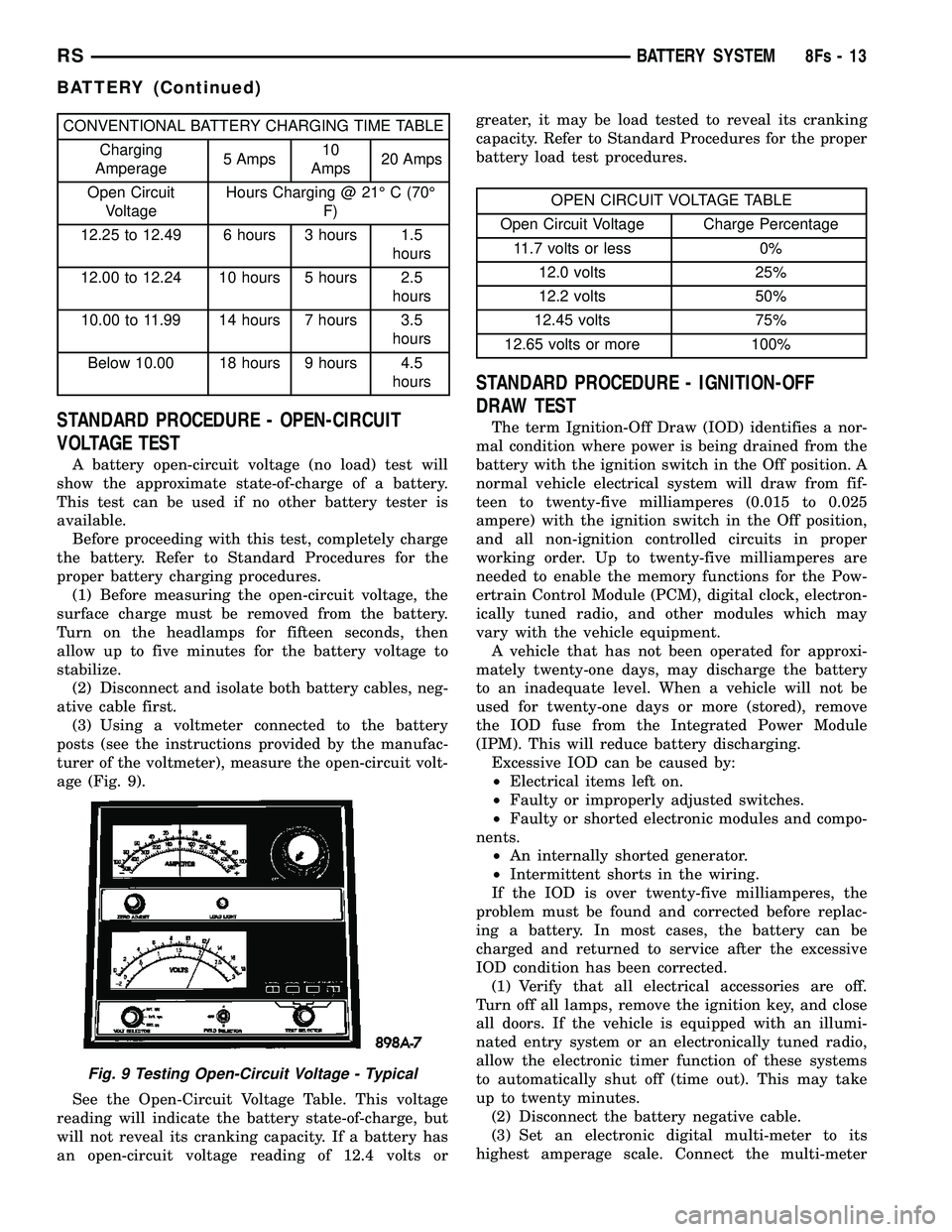
ative cable first. (3) Using a voltmeter connected to the battery
posts (see the instructions provided by the manufac-
turer of the voltmeter), measure the open-circuit volt-
age (Fig. 9).
See the Open-Circuit Voltage Table. This voltage
reading will indicate the battery state-of-charge, but
will not reveal its cranking capacity. If a battery has
an open-circuit voltage reading of 12.4 volts or greater, it may be load tested to reveal its cranking
capacity. Refer to Standard Procedures for the proper
battery load test procedures.
OPEN CIRCUIT VOLTAGE TABLE
Open Circuit Voltage Charge Percentage 11.7 volts or less 0% 12.0 volts 25%
12.2 volts 50%
12.45 volts 75%
12.65 volts or more 100%
STANDARD PROCEDURE - IGNITION-OFF
DRAW TEST
The term Ignition-Off Draw (IOD) identifies a nor-
mal condition where power is being drained from the
battery with the ignition switch in the Off position. A
normal vehicle electrical system will draw from fif-
teen to twenty-five milliamperes (0.015 to 0.025
ampere) with the ignition switch in the Off position,
and all non-ignition controlled circuits in proper
working order. Up to twenty-five milliamperes are
needed to enable the memory functions for the Pow-
ertrain Control Module (PCM), digital clock, electron-
ically tuned radio, and other modules which may
vary with the vehicle equipment. A vehicle that has not been operated for approxi-
mately twenty-one days, may discharge the battery
to an inadequate level. When a vehicle will not be
used for twenty-one days or more (stored), remove
the IOD fuse from the Integrated Power Module
(IPM). This will reduce battery discharging. Excessive IOD can be caused by:
² Electrical items left on.
² Faulty or improperly adjusted switches.
² Faulty or shorted electronic modules and compo-
nents. ² An internally shorted generator.
² Intermittent shorts in the wiring.
If the IOD is over twenty-five milliamperes, the
problem must be found and corrected before replac-
ing a battery. In most cases, the battery can be
charged and returned to service after the excessive
IOD condition has been corrected. (1) Verify that all electrical accessories are off.
Turn off all lamps, remove the ignition key, and close
all doors. If the vehicle is equipped with an illumi-
nated entry system or an electronically tuned radio,
allow the electronic timer function of these systems
to automatically shut off (time out). This may take
up to twenty minutes. (2) Disconnect the battery negative cable.
(3) Set an electronic digital multi-meter to its
highest amperage scale. Connect the multi-meter
Fig. 9 Testing Open-Circuit Voltage - Typical
RS BATTERY SYSTEM8Fs-13
BATTERY (Continued)
Page 472 of 2585
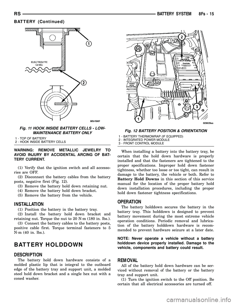
WARNING: REMOVE METALLIC JEWELRY TO
AVOID INJURY BY ACCIDENTAL ARCING OF BAT-
TERY CURRENT.(1) Verify that the ignition switch and all accesso-
ries are OFF. (2) Disconnect the battery cables from the battery
posts, negative first (Fig. 12). (3) Remove the battery hold down retaining nut.
(4) Remove the battery hold down bracket.
(5) Remove the battery from the vehicle.
INSTALLATION
(1) Position the battery in the battery tray.
(2) Install the battery hold down bracket and
retaining nut. Torque the nut to 20 N´m (180 in. lbs.). (3) Connect the battery cables to the battery posts,
positive cable first. Torque terminal fasteners to 5
N´m (40 in. lbs.).
BATTERY HOLDDOWN
DESCRIPTION
The battery hold down hardware consists of a
molded plastic lip that is integral to the outboard
edge of the battery tray and support unit, a molded
steel hold down bracket and a single hex nut with a
coned washer. When installing a battery into the battery tray, be
certain that the hold down hardware is properly
installed and that the fasteners are tightened to the
proper specifications. Improper hold down fastener
tightness, whether too loose or too tight, can result in
damage to the battery, the vehicle or both. Refer to
Battery Hold Downs in this section of this service
manual for the location of the proper battery hold
down installation procedures, including the proper
hold down fastener tightness specifications.
OPERATION
The battery holddown secures the battery in the
battery tray. This holddown is designed to prevent
battery movement during the most extreme vehicle
operation conditions. Periodic removal and lubrica-
tion of the battery holddown hardware is recom-
mended to prevent hardware seizure at a later date.
NOTE: Never operate a vehicle without a battery
holddown device properly installed. Damage to the
vehicle, components and battery could result.
REMOVAL
All of the battery hold down hardware can be ser-
viced without removal of the battery or the battery
tray and support unit. (1) Turn the ignition switch to the Off position. Be
certain that all electrical accessories are turned off.
Fig. 11 HOOK INSIDE BATTERY CELLS - LOW- MAINTENANCE BATTERY ONLY
1 - TOP OF BATTERY
2 - HOOK INSIDE BATTERY CELLS
Fig. 12 BATTERY POSITION & ORIENTATION
1 - BATTERY THERMOWRAP (IF EQUIPPED)
2 - INTEGRATED POWER MODULE
3 - FRONT CONTROL MODULE
RS BATTERY SYSTEM8Fs-15
BATTERY (Continued)
Page 477 of 2585
CHARGING
TABLE OF CONTENTS
page page
CHARGING DESCRIPTION - CHARGING SYSTEM .......20
OPERATION - CHARGING SYSTEM .........20
DIAGNOSIS AND TESTING - ON-BOARD DIAGNOSTIC SYSTEM .................21
SPECIFICATIONS GENERATOR ........................22
TORQUE ............................22
SPECIFICATIONS - BATTERY TEMPERATURE SENSOR ...............22
SPECIAL TOOLS .......................23
BATTERY TEMPERATURE SENSOR DESCRIPTION .........................23
OPERATION ...........................23
REMOVAL .............................23
GENERATOR DESCRIPTION .........................23
OPERATION ...........................23 REMOVAL
REMOVAL - 2.4L ......................23
REMOVAL - 2.5L ......................24
REMOVAL - 3.3/3.8L ...................25
INSTALLATION INSTALLATION - 2.4L ..................26
INSTALLATION - 2.5L ..................26
INSTALLATION - 3.3/3.8L ................26
GENERATOR DECOUPLER PULLEY DESCRIPTION .........................27
OPERATION ...........................27
DIAGNOSIS AND TESTING - GENERATOR DECOUPLER PULLEY ..................27
REMOVAL .............................28
INSTALLATION .........................28
VOLTAGE REGULATOR DESCRIPTION .........................29
OPERATION ...........................29
CHARGING
DESCRIPTION - CHARGING SYSTEM
The charging system consists of:
²Generator
² Decoupler Pulley (If equipped)
² Electronic Voltage Regulator (EVR) circuitry
within the Powertrain Control Module (PCM) ² Ignition switch (refer to the Ignition System sec-
tion for information) ² Battery (refer to the Battery section for informa-
tion) ² Ambient Air Temperature (If equipped)
² Inlet Air Temperature (calculated battery tem-
perature)(If equipped) ² Voltmeter (refer to the Instrument Cluster sec-
tion for information if equipped) ² Wiring harness and connections (refer to the
Wiring section for information) ² Accessory drive belt (refer to the Cooling section
for more information) ² Battery Temperature sensor (if equipped)
OPERATION - CHARGING SYSTEM
The charging system is turned on and off with the
ignition switch. The system is on when the engine is
running and the ASD relay is energized. The ASD
relay is energized when the PCM grounds the ASD
control circuit. This voltage is connected through the PCM or IPM (intelligent power module) (if equipped)
and supplied to one of the generator field terminals
(Gen. Source +) at the back of the generator.
The generator is driven by the engine through a
serpentine belt and pulley or decoupler pulley
arrangement. The amount of DC current produced by the gener-
ator is controlled by the EVR (field control) circuitry
contained within the PCM. This circuitry is con-
nected in series with the second rotor field terminal
and ground. An Ambient air temperature sensor is used to cal-
culate the temperature near the battery. This tem-
perature data, along with data from monitored line
voltage (battery voltage sense circuit), is used by the
PCM to vary the battery charging rate. This is done
by cycling the ground path to control the strength of
the rotor magnetic field. The PCM then compensates
and regulates generator current output accordingly
to maintain system voltage at the targeted system
voltage based on battery temperature. All vehicles are equipped with On-Board Diagnos-
tics (OBD). All OBD-sensed systems, including EVR
(field control) circuitry, are monitored by the PCM.
Each monitored circuit is assigned a Diagnostic Trou-
ble Code (DTC). The PCM will store a DTC in elec-
tronic memory for certain failures it detects and
illuminate the (MIL) lamp. Refer to On-Board Diag-
nostics in the Electronic Control Modules(Refer to 8 -
ELECTRICAL/ELECTRONIC CONTROL MOD-
8Fs - 20 CHARGINGRS
Page 478 of 2585
ULES/POWERTRAIN CONTROL MODULE -
DESCRIPTION) section for more DTC information.The Charging system ªBatteryº light indicates
problems with the charging system (voltage too high/
low, generator failure, etc.). If an extreme condition is
indicated, the lamp will be illuminated. The signal to
activate the lamp is sent via the PCI bus circuits.
The lamp is located on the instrument panel. Refer
to the Instrument Cluster section for additional infor-
mation. The PCM uses the ambient air temperature sensor
to control the charge system voltage. This tempera-
ture, along with data from monitored line voltage, is
used by the PCM to vary the battery charging rate.
The system voltage is higher at cold temperatures
and is gradually reduced as the calculated battery
temperature increases. The ambient temperature sensor is used to control
the battery voltage based upon ambient temperature
(approximation of battery temperature). The PCM
maintains the optimal output of the generator by
monitoring battery voltage and controlling it to a
range of 13.5 - 14.7 volts based on battery tempera-
ture.
DIAGNOSIS AND TESTING - ON-BOARD
DIAGNOSTIC SYSTEM
The Powertrain Control Module (PCM) monitors
critical input and output circuits of the charging sys-
tem, making sure they are operational. A Diagnostic
Trouble Code (DTC) is assigned to each input and
output circuit monitored by the OBD system. Some
circuits are checked continuously and some are
checked only under certain conditions. If the OBD system senses that a monitored circuit
is bad, it will put a DTC into electronic memory. The
DTC will stay in electronic memory as long as the
circuit continues to be bad. The PCM is programmed
to clear the memory after 40 good trip if the problem
does not occur again.
DIAGNOSTIC TROUBLE CODES
A DTC description can be read using the DRBIII t
scan tool. Refer to the appropriate Powertrain Diag-
nostic Procedures manual for information. A DTC does not identify which component in a cir-
cuit is bad. Thus, a DTC should be treated as a
symptom, not as the cause for the problem. In some
cases, because of the design of the diagnostic test
procedure, a DTC can be the reason for another DTC
to be set. Therefore, it is important that the test pro-
cedures be followed in sequence, to understand what
caused a DTC to be set. ERASING DIAGNOSTIC TROUBLE CODES
The DRBIII tScan Tool must be used to erase a
DTC. The following procedures may be used to diagnose
the charging system if: ² the check gauges lamp or battery lamp is illumi-
nated with the engine running ² the voltmeter (if equipped) does not register
properly ² an undercharged or overcharged battery condi-
tion occurs. Remember that an undercharged battery is often
caused by: ² accessories being left on with the engine not
running ² a faulty or improperly adjusted switch that
allows a lamp to stay on. Refer to Ignition-Off Draw
Test (Refer t o 8 - ELECTRICAL/BATTERY SYSTEM/
BATTERY - STANDARD PROCEDURE) ² loose generator belt.
INSPECTION The Powertrain Control Module (PCM) monitors
critical input and output circuits of the charging sys-
tem, making sure they are operational. A Diagnostic
Trouble Code (DTC) is assigned to each input and
output circuit monitored by the On-Board Diagnostic
(OBD) system. Some charging system circuits are
checked continuously, and some are checked only
under certain conditions. Refer to Diagnostic Trouble Codes in; Powertrain
Control Module; Electronic Control Modules for more
DTC information. This will include a complete list of
DTC's including DTC's for the charging system. To perform a complete test of the charging system,
refer to the appropriate Powertrain Diagnostic Proce-
dures service manual and the DRBIII tscan tool.
Perform the following inspections before attaching
the scan tool. (1) Inspect the battery condition. Refer to the Bat-
tery section (Refer t o 8 - ELECTRICAL/BATTERY
SYSTEM - DIAGNOSIS AND TESTING) for proce-
dures. (2) Inspect condition of battery cable terminals,
battery posts, connections at engine block, starter
solenoid and relay. They should be clean and tight.
Repair as required. (3) Inspect all fuses in both the fuseblock and
Power Distribution Center (PDC) or IPM (if
equipped) for tightness in receptacles. They should be
properly installed and tight. Repair or replace as
required. (4) Inspect generator mounting bolts for tightness.
Replace or tighten bolts if required. Refer to the Gen-
erator Removal/Installation section of this group for
RS CHARGING8Fs-21
CHARGING (Continued)
Page 496 of 2585
HEATED SYSTEMS
TABLE OF CONTENTS
page page
HEATED GLASS........................... 1
HEATED MIRRORS......................... 6HEATED SEAT SYSTEM..................... 7
HEATED GLASS
TABLE OF CONTENTS
page page
HEATED GLASS
DESCRIPTION..........................1
OPERATION............................2
DIAGNOSIS AND TESTING - REAR WINDOW
DEFOGGER SYSTEM...................2
REAR WINDOW DEFOGGER RELAY
DESCRIPTION..........................3
OPERATION............................3REMOVAL.............................3
INSTALLATION..........................3
REAR WINDOW DEFOGGER SWITCH
DESCRIPTION..........................4
OPERATION............................4
REAR WINDOW DEFOGGER GRID
STANDARD PROCEDURE - GRID LINE AND
TERMINAL REPAIR.....................4
HEATED GLASS
DESCRIPTION
CAUTION: Grid lines can be damaged or scraped
off with sharp instruments. Care should be taken in
cleaning glass or removing foreign materials,
decals or stickers. Normal glass cleaning solvents
or hot water used with rags or toweling is recom-
mended.
The rear window defogger system consists of two
vertical bus bars linked by a series of grid lines fired
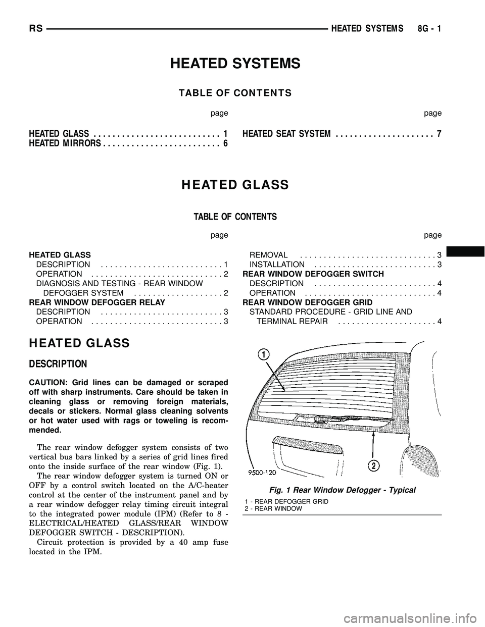
onto the inside surface of the rear window (Fig. 1).
The rear window defogger system is turned ON or
OFF by a control switch located on the A/C-heater
control at the center of the instrument panel and by
a rear window defogger relay timing circuit integral
to the integrated power module (IPM) (Refer to 8 -
ELECTRICAL/HEATED GLASS/REAR WINDOW
DEFOGGER SWITCH - DESCRIPTION).
Circuit protection is provided by a 40 amp fuse
located in the IPM.
Fig. 1 Rear Window Defogger - Typical
1 - REAR DEFOGGER GRID
2 - REAR WINDOW
RSHEATED SYSTEMS8G-1
Page 497 of 2585
OPERATION
When the rear window defogger button is
depressed to the On position, current is directed to
the rear defogger grid lines and the heated power
mirrors (if equipped). The heated grid lines heat the
glass to help clear the rear window and side mirror
surfaces of fog or frost.
The defogger system is controlled by a momentary
switch located in the A/C-heater control on the
instrument panel. A yellow indicator in the switch
will illuminate to indicate when the defogger system
is turned on. The integrated power module (IPM)
contains the defogger system control circuitry.
NOTE:
The rear window defogger turns off automat-
ically after approximately 10 minutes of initial opera-
tion. Each following activation cycle of the defogger
system will last approximately five minutes.
The defogger system will be automatically turned
off after a programmed time interval of about ten
minutes. After the initial time interval has expired, if
the defogger switch is turned on again during the
same ignition cycle, the defogger system will auto-
matically turn off after about five minutes.
The defogger system will automatically shut off if
the ignition switch is turned to the Off position, or it
can be turned off manually by depressing the defog-
ger switch a second time.
DIAGNOSIS AND TESTING - REAR WINDOW
DEFOGGER SYSTEM
The electrically heated rear window defogger oper-
ation can be checked on the vehicle in the following
manner:
(1) Turn the ignition switch to the On position.
(2) Make sure that the defogger switch is Off.
(3) Using a ammeter on the battery, turn the rear
defogger control switch to the On position, a distinct
increase in amperage draw should be noted.
(4) The rear window defogger operation can be
checked by feeling the glass. A distinct difference in
temperature between the grid lines and adjacent
clear glass should be detected in three to four min-
utes of operation.
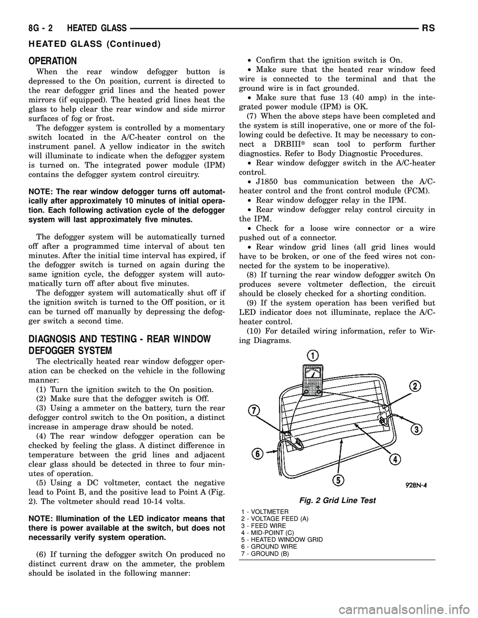
(5) Using a DC voltmeter, contact the negative
lead to Point B, and the positive lead to Point A (Fig.
2). The voltmeter should read 10-14 volts.
NOTE: Illumination of the LED indicator means that
there is power available at the switch, but does not
necessarily verify system operation.
(6) If turning the defogger switch On produced no
distinct current draw on the ammeter, the problem
should be isolated in the following manner:²Confirm that the ignition switch is On.
²Make sure that the heated rear window feed
wire is connected to the terminal and that the
ground wire is in fact grounded.
²Make sure that fuse 13 (40 amp) in the inte-
grated power module (IPM) is OK.
(7) When the above steps have been completed and
the system is still inoperative, one or more of the fol-
lowing could be defective. It may be necessary to con-
nect a DRBIIItscan tool to perform further
diagnostics. Refer to Body Diagnostic Procedures.
²Rear window defogger switch in the A/C-heater
control.
²J1850 bus communication between the A/C-
heater control and the front control module (FCM).
²Rear window defogger relay in the IPM.
²Rear window defogger relay control circuity in
the IPM.
²Check for a loose wire connector or a wire
pushed out of a connector.
²Rear window grid lines (all grid lines would
have to be broken, or one of the feed wires not con-
nected for the system to be inoperative).
(8) If turning the rear window defogger switch On
produces severe voltmeter deflection, the circuit
should be closely checked for a shorting condition.
(9) If the system operation has been verified but
LED indicator does not illuminate, replace the A/C-
heater control.
(10) For detailed wiring information, refer to Wir-
ing Diagrams.
Fig. 2 Grid Line Test
1 - VOLTMETER
2 - VOLTAGE FEED (A)
3 - FEED WIRE
4 - MID-POINT (C)
5 - HEATED WINDOW GRID
6 - GROUND WIRE
7 - GROUND (B)
8G - 2 HEATED GLASSRS
HEATED GLASS (Continued)
Page 498 of 2585
REAR WINDOW DEFOGGER
RELAY
DESCRIPTION
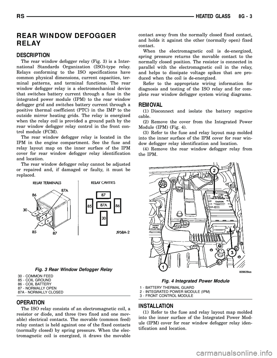
The rear window defogger relay (Fig. 3) is a Inter-
national Standards Organization (ISO)-type relay.
Relays conforming to the ISO specifications have
common physical dimensions, current capacities, ter-
minal patterns, and terminal functions. The rear
window defogger relay is a electromechanical device
that switches battery current through a fuse in the
integrated power module (IPM) to the rear window
defogger grid and switches battery current through a
positive thermal coefficient (PTC) in the IMP to the
outside mirror heating grids. The relay is energized
when the relay coil is provided a ground path by the
rear window defogger relay control in the front con-
trol module (FCM).
The rear window defogger relay is located in the
IPM in the engine compartment. See the fuse and
relay layout map on the inner surface of the IPM
cover for rear window defogger relay identification
and location.
The rear window defogger relay cannot be adjusted
or repaired and, if damaged or faulty, it must be
replaced.
OPERATION
The ISO relay consists of an electromagnetic coil, a
resistor or diode, and three (two fixed and one mov-
able) electrical contacts. The movable (common feed)
relay contact is held against one of the fixed contacts
(normally closed) by spring pressure. When the elec-
tromagnetic coil is energized, it draws the movablecontact away from the normally closed fixed contact,
and holds it against the other (normally open) fixed
contact.
When the electromagnetic coil is de-energized,
spring pressure returns the movable contact to the
normally closed position. The resistor is connected in
parallel with the electromagnetic coil in the relay,
and helps to dissipate voltage spikes that are pro-
duced when the coil is de-energized.
Refer to the appropriate wiring information for
diagnosis and testing of the ISO relay and for com-
plete rear window defogger system wiring diagrams.
REMOVAL
(1) Disconnect and isolate the battery negative
cable.
(2) Remove the cover from the Integrated Power
Module (IPM) (Fig. 4).
(3) Refer to the fuse and relay layout map molded
into the inner surface of the IPM cover for rear win-
dow defogger relay identification and location.
(4) Remove the rear window defogger relay from
the IPM.
INSTALLATION
(1) Refer to the fuse and relay layout map molded
into the inner surface of the Integrated Power Mod-
ule (IPM) cover for rear window defogger relay iden-
tification and location.
Fig. 3 Rear Window Defogger Relay
30 - COMMON FEED
85 - COIL GROUND
86 - COIL BATTERY
87 - NORMALLY OPEN
87A - NORMALLY CLOSED
Fig. 4 Integrated Power Module
1 - BATTERY THERMAL GUARD
2 - INTEGRATED POWER MODULE (IPM)
3 - FRONT CONTROL MODULE
RSHEATED GLASS8G-3