8e electrical control module CHRYSLER VOYAGER 2004 User Guide
[x] Cancel search | Manufacturer: CHRYSLER, Model Year: 2004, Model line: VOYAGER, Model: CHRYSLER VOYAGER 2004Pages: 2585, PDF Size: 62.54 MB
Page 387 of 2585
motors, and fuel pumps that have been found to be
potential sources of RFI or EMI.
OPERATION
There are two common strategies that can be used
to suppress Radio Frequency Interference (RFI) and
ElectroMagnetic Interference (EMI) radio noise. The
first suppression strategy involves preventing the
production of RFI and EMI electromagnetic signals
at their sources. The second suppression strategy
involves preventing the reception of RFI and EMI
electromagnetic signals by the audio system compo-
nents.
The use of braided ground straps in key locations
is part of the RFI and EMI prevention strategy.
These ground straps ensure adequate ground paths,
particularly for high current components such as
many of those found in the starting, charging, igni-
tion, engine control and transmission control sys-
tems. An insufficient ground path for any of these
high current components may result in radio noise
caused by induced voltages created as the high cur-
rent seeks alternative ground paths through compo-
nents or circuits intended for use by, or in close
proximity to the audio system components or circuits.
Preventing the reception of RFI and EMI is accom-
plished by ensuring that the audio system compo-
nents are correctly installed in the vehicle. Loose,
corroded or improperly soldered wire harness connec-
tions, improperly routed wiring and inadequate audio
system component grounding can all contribute to
the reception of RFI and EMI. A properly grounded
antenna body and radio chassis, as well as a shielded
antenna coaxial cable with clean and tight connec-
tions will each help reduce the potential for reception
of RFI and EMI.
REMOTE SWITCHES
DESCRIPTION
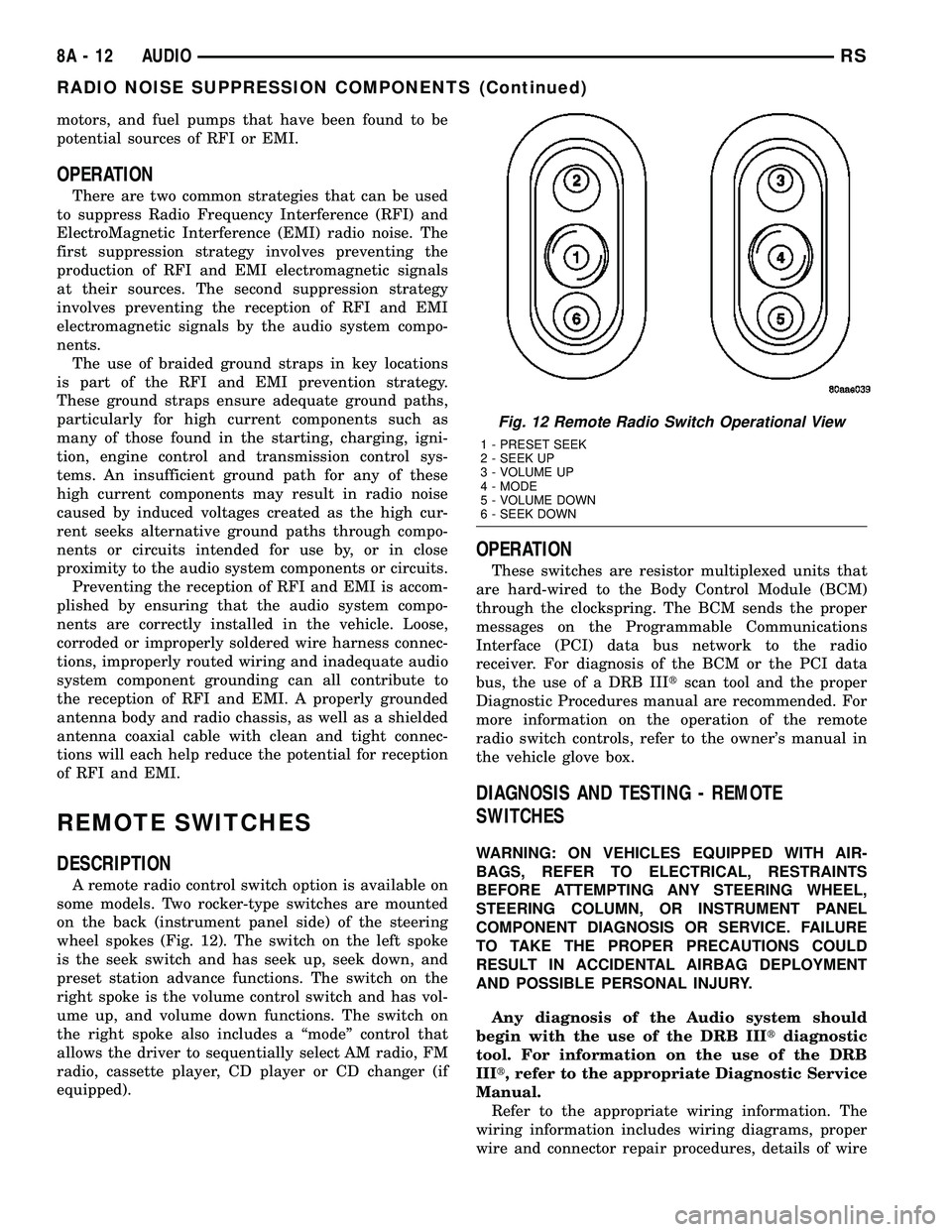
A remote radio control switch option is available on
some models. Two rocker-type switches are mounted
on the back (instrument panel side) of the steering
wheel spokes (Fig. 12). The switch on the left spoke
is the seek switch and has seek up, seek down, and
preset station advance functions. The switch on the
right spoke is the volume control switch and has vol-
ume up, and volume down functions. The switch on
the right spoke also includes a ªmodeº control that
allows the driver to sequentially select AM radio, FM
radio, cassette player, CD player or CD changer (if
equipped).
OPERATION
These switches are resistor multiplexed units that
are hard-wired to the Body Control Module (BCM)
through the clockspring. The BCM sends the proper
messages on the Programmable Communications
Interface (PCI) data bus network to the radio
receiver. For diagnosis of the BCM or the PCI data
bus, the use of a DRB IIItscan tool and the proper
Diagnostic Procedures manual are recommended. For
more information on the operation of the remote
radio switch controls, refer to the owner's manual in
the vehicle glove box.
DIAGNOSIS AND TESTING - REMOTE
SWITCHES
WARNING: ON VEHICLES EQUIPPED WITH AIR-
BAGS, REFER TO ELECTRICAL, RESTRAINTS
BEFORE ATTEMPTING ANY STEERING WHEEL,
STEERING COLUMN, OR INSTRUMENT PANEL
COMPONENT DIAGNOSIS OR SERVICE. FAILURE
TO TAKE THE PROPER PRECAUTIONS COULD
RESULT IN ACCIDENTAL AIRBAG DEPLOYMENT
AND POSSIBLE PERSONAL INJURY.
Any diagnosis of the Audio system should
begin with the use of the DRB IIItdiagnostic
tool. For information on the use of the DRB
IIIt, refer to the appropriate Diagnostic Service
Manual.
Refer to the appropriate wiring information. The
wiring information includes wiring diagrams, proper
wire and connector repair procedures, details of wire
Fig. 12 Remote Radio Switch Operational View
1 - PRESET SEEK
2 - SEEK UP
3 - VOLUME UP
4 - MODE
5 - VOLUME DOWN
6 - SEEK DOWN
8A - 12 AUDIORS
RADIO NOISE SUPPRESSION COMPONENTS (Continued)
Page 388 of 2585
harness routing and retention, connector pin-out
information and location views for the various wire
harness connectors, splices and grounds.
(1) Disconnect and isolate the battery negative
cable. Wait two minutes for the airbag system capac-
itor to discharge before further service.
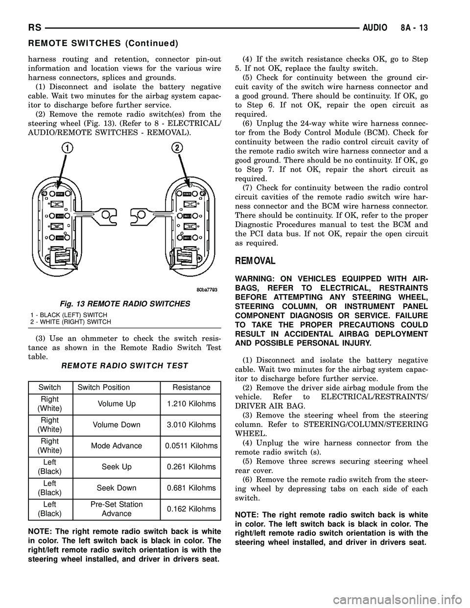
(2) Remove the remote radio switch(es) from the
steering wheel (Fig. 13). (Refer to 8 - ELECTRICAL/
AUDIO/REMOTE SWITCHES - REMOVAL).
(3) Use an ohmmeter to check the switch resis-
tance as shown in the Remote Radio Switch Test
table.
REMOTE RADIO SWITCH TEST
Switch Switch Position Resistance
Right
(White)Volume Up 1.210 Kilohms
Right
(White)Volume Down 3.010 Kilohms
Right
(White)Mode Advance 0.0511 Kilohms
Left
(Black)Seek Up 0.261 Kilohms
Left
(Black)Seek Down 0.681 Kilohms
Left
(Black)Pre-Set Station
Advance0.162 Kilohms
NOTE: The right remote radio switch back is white
in color. The left switch back is black in color. The
right/left remote radio switch orientation is with the
steering wheel installed, and driver in drivers seat.(4) If the switch resistance checks OK, go to Step
5. If not OK, replace the faulty switch.
(5) Check for continuity between the ground cir-
cuit cavity of the switch wire harness connector and
a good ground. There should be continuity. If OK, go
to Step 6. If not OK, repair the open circuit as
required.
(6) Unplug the 24-way white wire harness connec-
tor from the Body Control Module (BCM). Check for
continuity between the radio control circuit cavity of
the remote radio switch wire harness connector and a
good ground. There should be no continuity. If OK, go
to Step 7. If not OK, repair the short circuit as
required.
(7) Check for continuity between the radio control
circuit cavities of the remote radio switch wire har-
ness connector and the BCM wire harness connector.
There should be continuity. If OK, refer to the proper
Diagnostic Procedures manual to test the BCM and
the PCI data bus. If not OK, repair the open circuit
as required.
REMOVAL
WARNING: ON VEHICLES EQUIPPED WITH AIR-
BAGS, REFER TO ELECTRICAL, RESTRAINTS
BEFORE ATTEMPTING ANY STEERING WHEEL,
STEERING COLUMN, OR INSTRUMENT PANEL
COMPONENT DIAGNOSIS OR SERVICE. FAILURE
TO TAKE THE PROPER PRECAUTIONS COULD
RESULT IN ACCIDENTAL AIRBAG DEPLOYMENT
AND POSSIBLE PERSONAL INJURY.
(1) Disconnect and isolate the battery negative
cable. Wait two minutes for the airbag system capac-
itor to discharge before further service.
(2) Remove the driver side airbag module from the
vehicle. Refer to ELECTRICAL/RESTRAINTS/
DRIVER AIR BAG.
(3) Remove the steering wheel from the steering
column. Refer to STEERING/COLUMN/STEERING
WHEEL.
(4) Unplug the wire harness connector from the
remote radio switch (s).
(5) Remove three screws securing steering wheel
rear cover.
(6) Remove the remote radio switch from the steer-
ing wheel by depressing tabs on each side of each
switch.
NOTE: The right remote radio switch back is white
in color. The left switch back is black in color. The
right/left remote radio switch orientation is with the
steering wheel installed, and driver in drivers seat.
Fig. 13 REMOTE RADIO SWITCHES
1 - BLACK (LEFT) SWITCH
2 - WHITE (RIGHT) SWITCH
RSAUDIO8A-13
REMOTE SWITCHES (Continued)
Page 389 of 2585

INSTALLATION
WARNING: ON VEHICLES EQUIPPED WITH AIR-
BAGS, REFER TO ELECTRICAL, RESTRAINTS
BEFORE ATTEMPTING ANY STEERING WHEEL,
STEERING COLUMN, OR INSTRUMENT PANEL
COMPONENT DIAGNOSIS OR SERVICE. FAILURE
TO TAKE THE PROPER PRECAUTIONS COULD
RESULT IN ACCIDENTAL AIRBAG DEPLOYMENT
AND POSSIBLE PERSONAL INJURY.
(1) Install remote radio switch to the steering
wheel.
(2) Install three screws securing steering wheel
rear cover.
(3) Connect the wire harness to the remote radio
switch.
(4) Install the steering wheel. Refer to STEERING/
COLUMN/STEERING WHEEL.
(5) Install the driver side airbag module. Refer to
ELECTRICAL/RESTRAINTS/DRIVER AIRBAG.
(6) Connect the battery negative cable.
SPEAKER
DIAGNOSIS AND TESTING - SPEAKER
WARNING: DISABLE THE AIRBAG SYSTEM
BEFORE ATTEMPTING ANY STEERING WHEEL,
STEERING COLUMN, SEAT BELT TENSIONER, SIDE
AIRBAG, OR INSTRUMENT PANEL COMPONENT
DIAGNOSIS OR SERVICE. DISCONNECT AND ISO-
LATE THE BATTERY NEGATIVE (GROUND) CABLE,
THEN WAIT TWO MINUTES FOR THE AIRBAG SYS-
TEM CAPACITOR TO DISCHARGE BEFORE PER-
FORMING FURTHER DIAGNOSIS OR SERVICE. THIS
IS THE ONLY SURE WAY TO DISABLE THE AIRBAG
SYSTEM. FAILURE TO TAKE THE PROPER PRE-
CAUTIONS COULD RESULT IN ACCIDENTAL AIR-
BAG DEPLOYMENT AND POSSIBLE PERSONAL
INJURY.
Any diagnosis of the Audio system should
begin with the use of the DRB IIItdiagnostic
tool. For information on the use of the DRB
IIIt, refer to the appropriate Diagnostic Service
Manual.
Refer to the appropriate wiring information. The
wiring information includes wiring diagrams, proper
wire and connector repair procedures, details of wire
harness routing and retention, connector pin-out
information and location views for the various wire
harness connectors, splices and grounds.
CAUTION: The speaker output of the radio is a
ªfloating groundº system. Do not allow any speakerlead to short to ground, as damage to the radio
may result.
(1) If all speakers are inoperative, check the radio
fuses in the junction block. If OK, go to Step 2. If not
OK, repair the shorted circuit or component as
required and replace the faulty fuse.
(2) Turn the ignition switch to the ON position.
Turn the radio receiver ON. Adjust the balance and
fader control controls to check the performance of
each individual speaker. Note the speaker locations
that are not performing correctly. Go to Step 3.
(3) Turn the radio receiver OFF. Turn the ignition
OFF. Disconnect and isolate the battery negative
cable. Remove the radio receiver.
(4) Check both the speaker feed (+) circuit and
return (-) circuit cavities for the inoperative speaker
at the radio receiver wire harness connector for con-
tinuity to ground. There should be no continuity. If
OK, go to Step 5. If not OK, repair the shorted
speaker feed (+) and/or return (-) circuits(s) to the
speaker as required.
(5) Disconnect wire harness connector at the inop-
erative speaker. Check for continuity between the
speaker feed (+) circuit cavities of the radio receiver
wire harness connector and the speaker wire harness
connector. Repeat the check between the speaker
return (-) circuit cavities of the radio receiver wire
harness connector and the speaker wire harness con-
nector. In each case, there should be continuity. If
OK, replace the faulty speaker. If not OK, repair the
open speaker feed (+) and/or return (-) circuits(s) as
required.
REMOVAL
D-PILLAR SPEAKER
(1) Disconnect and isolate the battery negative
cable.
(2) Remove rear header trim (right side speaker).
(3) Remove jack cover (left side speaker).
(4) Remove liftgate scuff plate.
(5) Remove upper seat belt bolt. (Refer to 8 -
ELECTRICAL/RESTRAINTS/SEAT BELT OUT-
BOARD FRONT - REMOVAL).
(6) Partially remove quarter trim panel to access
the D-pillar speaker.
(7) Slide the speaker from the retainer (Fig. 14).
(8) Disconnect the wire harness connector from the
speaker.
FRONT DOOR SPEAKER
(1) Disconnect and isolate the battery negative
cable.
(2) Remove the front door trim panel. (Refer to 23
- BODY/DOOR - FRONT/TRIM PANEL - REMOV-
AL).
8A - 14 AUDIORS
REMOTE SWITCHES (Continued)
Page 399 of 2585
be automatically cleared from the CAB memory after
the identical fault has not been seen during the next
3,500 miles. Drive-off may be required for the amber
ABS warning indicator lamp to go out on the next
ignition cycle.
CAB INPUTS
²Wheel speed sensors (four)
²Brake lamp switch
²Ignition switch
²System and pump voltage
²Ground
²Traction control switch (if equipped)
²Diagnostic communication (PCI)
CAB OUTPUTS
²Amber ABS warning indicator lamp actuation
(via BUS)
²Red BRAKE warning indicator lamp actuation
(via BUS)
²Instrument cluster (MIC) communication (PCI)
²Traction control lamps (if equipped)
²Diagnostic communication (PCI, via BUS)
REMOVAL
(1) Disconnect the battery cables.
(2) Remove the battery (Refer to 8 - ELECTRI-
CAL/BATTERY SYSTEM/BATTERY - REMOVAL).
(3) Disconnect the vacuum hose connector at the
tank built into the battery tray.
(4) Remove the screw securing the coolant filler
neck to the battery tray.
(5) Remove the battery tray (Refer to 8 - ELEC-
TRICAL/BATTERY SYSTEM/TRAY - REMOVAL).
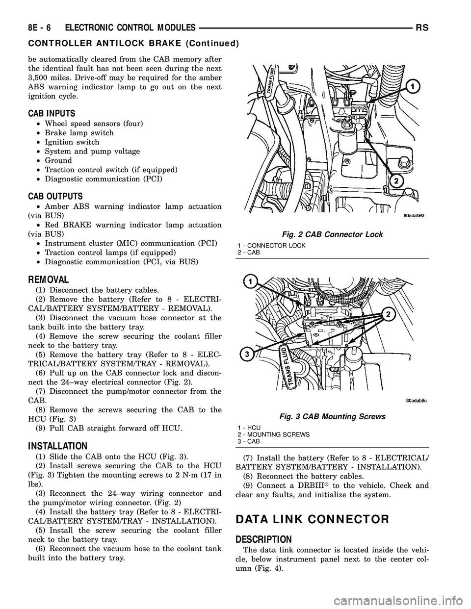
(6) Pull up on the CAB connector lock and discon-
nect the 24±way electrical connector (Fig. 2).
(7) Disconnect the pump/motor connector from the
CAB.
(8) Remove the screws securing the CAB to the
HCU (Fig. 3)
(9) Pull CAB straight forward off HCU.
INSTALLATION
(1) Slide the CAB onto the HCU (Fig. 3).
(2) Install screws securing the CAB to the HCU
(Fig. 3) Tighten the mounting screws to 2 N´m (17 in
lbs).
(3) Reconnect the 24±way wiring connector and
the pump/motor wiring connector. (Fig. 2)
(4) Install the battery tray (Refer to 8 - ELECTRI-
CAL/BATTERY SYSTEM/TRAY - INSTALLATION).
(5) Install the screw securing the coolant filler
neck to the battery tray.
(6) Reconnect the vacuum hose to the coolant tank
built into the battery tray.(7) Install the battery (Refer to 8 - ELECTRICAL/
BATTERY SYSTEM/BATTERY - INSTALLATION).
(8) Reconnect the battery cables.
(9) Connect a DRBIIItto the vehicle. Check and
clear any faults, and initialize the system.
DATA LINK CONNECTOR
DESCRIPTION
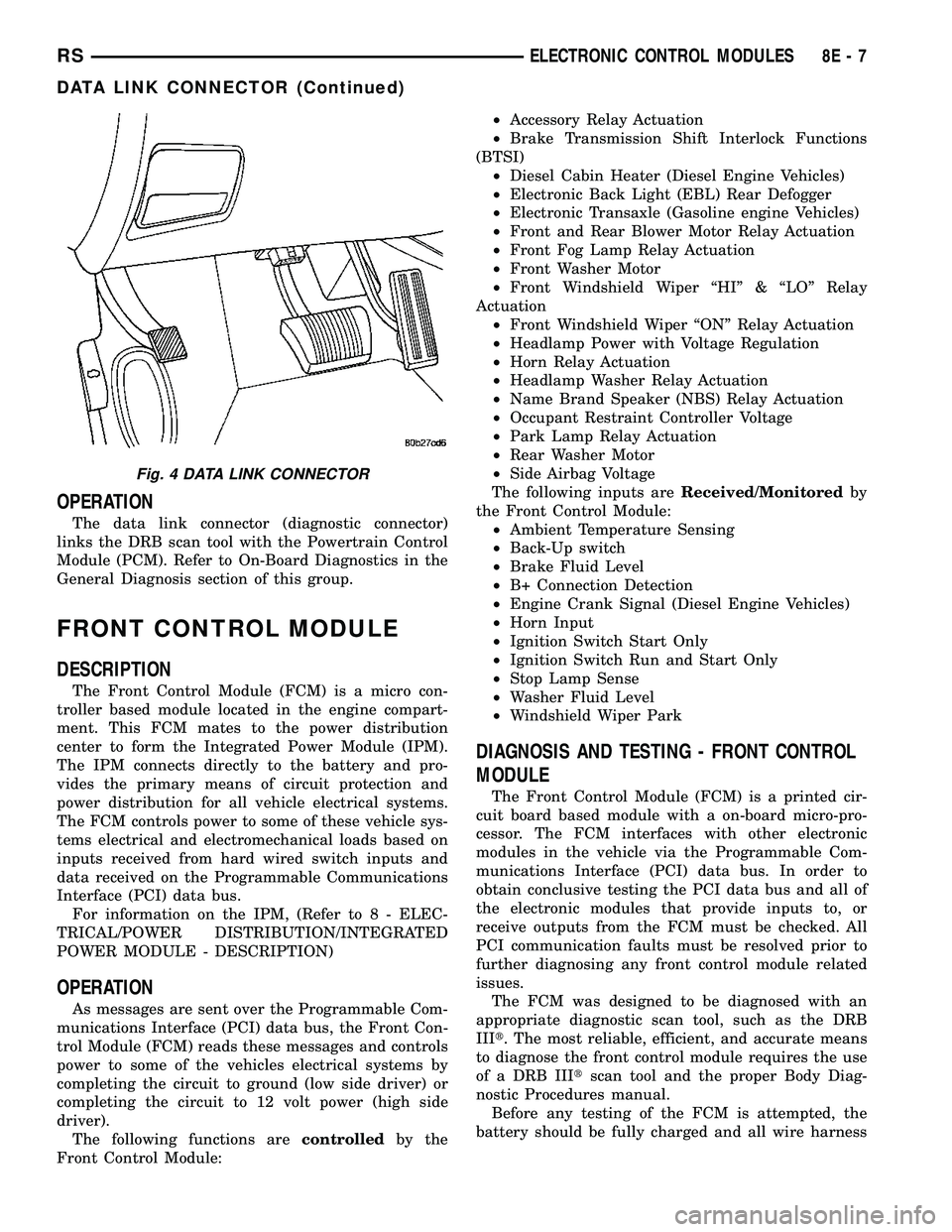
The data link connector is located inside the vehi-
cle, below instrument panel next to the center col-
umn (Fig. 4).
Fig. 2 CAB Connector Lock
1 - CONNECTOR LOCK
2 - CAB
Fig. 3 CAB Mounting Screws
1 - HCU
2 - MOUNTING SCREWS
3 - CAB
8E - 6 ELECTRONIC CONTROL MODULESRS
CONTROLLER ANTILOCK BRAKE (Continued)
Page 400 of 2585
OPERATION
The data link connector (diagnostic connector)
links the DRB scan tool with the Powertrain Control
Module (PCM). Refer to On-Board Diagnostics in the
General Diagnosis section of this group.
FRONT CONTROL MODULE
DESCRIPTION
The Front Control Module (FCM) is a micro con-
troller based module located in the engine compart-
ment. This FCM mates to the power distribution
center to form the Integrated Power Module (IPM).
The IPM connects directly to the battery and pro-
vides the primary means of circuit protection and
power distribution for all vehicle electrical systems.
The FCM controls power to some of these vehicle sys-
tems electrical and electromechanical loads based on
inputs received from hard wired switch inputs and
data received on the Programmable Communications
Interface (PCI) data bus.
For information on the IPM, (Refer to 8 - ELEC-
TRICAL/POWER DISTRIBUTION/INTEGRATED
POWER MODULE - DESCRIPTION)
OPERATION
As messages are sent over the Programmable Com-
munications Interface (PCI) data bus, the Front Con-
trol Module (FCM) reads these messages and controls
power to some of the vehicles electrical systems by
completing the circuit to ground (low side driver) or
completing the circuit to 12 volt power (high side
driver).
The following functions arecontrolledby the
Front Control Module:²Accessory Relay Actuation
²Brake Transmission Shift Interlock Functions
(BTSI)
²Diesel Cabin Heater (Diesel Engine Vehicles)
²Electronic Back Light (EBL) Rear Defogger
²Electronic Transaxle (Gasoline engine Vehicles)
²Front and Rear Blower Motor Relay Actuation
²Front Fog Lamp Relay Actuation
²Front Washer Motor
²Front Windshield Wiper ªHIº & ªLOº Relay
Actuation
²Front Windshield Wiper ªONº Relay Actuation
²Headlamp Power with Voltage Regulation
²Horn Relay Actuation
²Headlamp Washer Relay Actuation
²Name Brand Speaker (NBS) Relay Actuation
²Occupant Restraint Controller Voltage
²Park Lamp Relay Actuation
²Rear Washer Motor
²Side Airbag Voltage
The following inputs areReceived/Monitoredby
the Front Control Module:
²Ambient Temperature Sensing
²Back-Up switch
²Brake Fluid Level
²B+ Connection Detection
²Engine Crank Signal (Diesel Engine Vehicles)
²Horn Input
²Ignition Switch Start Only
²Ignition Switch Run and Start Only
²Stop Lamp Sense
²Washer Fluid Level
²Windshield Wiper Park
DIAGNOSIS AND TESTING - FRONT CONTROL
MODULE
The Front Control Module (FCM) is a printed cir-
cuit board based module with a on-board micro-pro-
cessor. The FCM interfaces with other electronic
modules in the vehicle via the Programmable Com-
munications Interface (PCI) data bus. In order to
obtain conclusive testing the PCI data bus and all of
the electronic modules that provide inputs to, or
receive outputs from the FCM must be checked. All
PCI communication faults must be resolved prior to
further diagnosing any front control module related
issues.
The FCM was designed to be diagnosed with an
appropriate diagnostic scan tool, such as the DRB
IIIt. The most reliable, efficient, and accurate means
to diagnose the front control module requires the use
of a DRB IIItscan tool and the proper Body Diag-
nostic Procedures manual.
Before any testing of the FCM is attempted, the
battery should be fully charged and all wire harness
Fig. 4 DATA LINK CONNECTOR
RSELECTRONIC CONTROL MODULES8E-7
DATA LINK CONNECTOR (Continued)
Page 401 of 2585

and ground connections inspected around the affected
areas on the vehicle.
REMOVAL
(1) Disconnect and isolate the negative and posi-
tive battery cables from the battery.
(2) Remove the battery from the vehicle. Refer to
the procedure in Battery Systems.
(3) Using a long flat-bladed screwdriver, gently
twist the Integrated Power Module (IPM) retaining
clip outboard to free the IPM from its mounting
bracket (Fig. 5). Rotate IPM upward to access the
Front Control Module (FCM) retaining screws.
(4) Remove the front control module retaining
screws.
(5) Using both hands, pull the FCM straight from
the IPM assembly to disconnect the 49-way electrical
connector (Fig. 6) and remove the front control mod-
ule from the vehicle.
INSTALLATION
NOTE: Front Control Module must be programmed
to the correct radio EQ curve using the DRB IIIT.
This will ensure that the audio system is operating
correctly.
(1) Install the Front Control Module (FCM) in the
Integrated Power Module (IPM) assembly by pushing
the 49-way electrical connector straight in.
(2) Install the FCM retaining screws. Torque the
screws to 1 N´m (7 in. lbs).
(3) Rotate the IPM assembly downward to secure
in mounting bracket.(4) Install the battery in the vehicle. Refer to the
procedure in Battery Systems.
(5) Connect the positive and negative battery
cables.
(6) Using the DRB IIIt, under ªFRONT CON-
TROL MODULEº then ªMISCº program the EQ
curve of the radio into the Front Control Module.
Refer to the appropriate diagnostic manual.
NOTE: If the vehicle is not equipped with Name
Brand Speakers (Infinity, etc.) or Headlamp Washers
the DRB IIITmust be used to Disable the appropri-
ate relays in the Integrated Power Module Assem-
bly.
HEATED SEAT MODULE
DESCRIPTION
Vehicles equipped with heated seats utilize two
heated seat modules. The heated seat modules (Fig.
7) are located under the front seats, where they are
secured to the seat cushion pans. The left heated
seat module controls the left heated seat, and the
right controls the right. Each heated seat module has
three connector receptacles that allow the modules to
be connected to all of the required inputs and out-
puts through the seat wire harness.
The heated seat modules are an electronic micro-
processor controlled device designed and programmed
to use inputs from the ignition switch, heated seat
Fig. 5 REMOVING INTEGRATED POWER MODULE
Fig. 6 FRONT CONTROL MODULE
1 - FRONT CONTROL MODULE
8E - 8 ELECTRONIC CONTROL MODULESRS
FRONT CONTROL MODULE (Continued)
Page 402 of 2585

switch and the heated seat sensor to operate and
control the heated seat elements in the front seat.
The heated seat modules cannot be repaired. If
either of the heated seat modules are damaged or
faulty, the entire module must be replaced.
OPERATION
The heated seat module operates on fused battery
current received from the integrated power module.
The module is grounded at all times through the seat
wire harness. Inputs to the module include a resistor
multiplexed heated seat switch request circuit for the
heated seat switch and the heated seat sensor inputs
from the seat cushions of each front seat. In response
to those inputs the heated seat module controls bat-
tery current feeds to the heated seat elements.
When a heated seat switch request signal is
received by the heated seat module and the enable
input is high, the heated seat module energizes the
selected heated seat sensor circuit and the sensor
provides the module with an input indicating the
surface temperature of the selected seat cushion.
The Low heat set point is about 35É C (95É F), and
the High heat set point is about 40É C (104É F). If the
seat cushion surface temperature input is below the
temperature set point for the selected temperature
setting, the heated seat module energizes an N-chan-
nel Field Effect Transistor (N-FET) within the mod-
ule which energizes the heated seat elements in theselected seat cushion and back. When the sensor
input to the module indicates the correct tempera-
ture set point has been achieved, the module de-en-
ergizes the N-FET which de-energizes the heated
seat elements. The heated seat module will continue
to cycle the N-FET as needed to maintain the
selected temperature set point.
DIAGNOSIS AND TESTING - HEATED SEAT
MODULE
If a heated seat heats but one or both indicator
lamps on the heated seat switch fail to operate, test
the heated seat switch. Refer toDiagnosis and
Testing Heated Seat Switchin Heated Seats for
heated seat switch diagnosis and testing procedures.
If the heated seat switch checks OK, proceed as fol-
lows.
(1) Check the heated seat element (Refer to 8 -
ELECTRICAL/HEATED SEATS/HEATED SEAT
ELEMENT - DIAGNOSIS AND TESTING).
(2) Check the heated seat sensor (Refer to 8 -
ELECTRICAL/HEATED SEATS/HEATED SEAT
SENSOR - DIAGNOSIS AND TESTING).
(3) Check the heated seat switch (Refer to 8 -
ELECTRICAL/HEATED SEATS/DRIVER HEATED
SEAT SWITCH - DIAGNOSIS AND TESTING).
NOTE: Refer to Wiring for the location of complete
heated seat system wiring diagrams and connector
pin-out information.
(4) Using a voltmeter, back probe the appropriate
heated seat module connector, do not disconnect.
Check for battery voltage at the appropriate pin cav-
ities. If OK go to Step 5. If not OK, repair the open
or shorted voltage supply circuit as required.
(5) Using a ohmmeter, back probe the appropriate
heated seat module connector, do not disconnect.
Check for proper continuity to ground on the ground
pin cavities. Continuity should be present. If OK
replace the heated seat module with a known good
unit and retest system, if Not OK, Repair the open or
shorted ground circuit as required.
REMOVAL
(1) Disconnect and isolate the negative battery
cable.
(2) Remove the appropriate front seat from the
vehicle (Refer to 23 - BODY/SEATS/SEAT - REMOV-
AL).
(3) Unsnap the module from the seat cushion pan.
(4) Disconnect the module wire harness connec-
tors.
Fig. 7 HEATED SEAT MODULE
1 - HEATED SEAT MODULE
2 - C1 CONNECTOR
3 - C3 CONNECTOR
4 - C1 CONNECTOR
RSELECTRONIC CONTROL MODULES8E-9
HEATED SEAT MODULE (Continued)
Page 403 of 2585
INSTALLATION
(1) Connect the module wire harness connectors.
(2) Snap the module on the seat cushion pan.
(3) Install the appropriate front seat in the vehicle
(Refer to 23 - BODY/SEATS/SEAT - INSTALLA-
TION).
(4) Connect and isolate the negative battery cable.
MEMORY SEAT/MIRROR
MODULE
DESCRIPTION
Vehicles equipped with the memory seat/mirror
option, utilize a memory module located under the
drivers front seat. This module is basically wired in-
line between the power seat switch and the power
seat track/adjuster motors, or in-line between the
power mirror switch and the power side view mir-
ror(s) motor(s). The MSMM contains a central pro-
cessing unit that communicates with other modules
on the Programmable Communications Interface
(PCI) data bus network.
The Memory Seat/Mirror Module (MSMM) receives
hard wired inputs from the driver power seat switch
and the potentiometers on each of the driver side
power seat track motors, or from the power mirror
switch and the potentiometers on the side view mir-
ror. The MSMM receives messages over the PCI data
bus from the Body Control Module (BCM) (memory
switch status), the Powertrain Control Module (PCM)
(vehicle speed status). The MSMM will prevent the
seat memory recall function from being initiated if
the driver side seat belt is buckled, if the transmis-
sion gear selector lever is not in the Park or Neutral
positions, or if the vehicle is moving.
For diagnosis of the MSMM or the PCI data bus, a
DRB IIItscan tool and the proper Diagnostic Proce-
dures manual are recommended. The MSMM cannot
be repaired and, if faulty or damaged, it must be
replaced. Refer toMemory Systemin the Power
Seat or Power Mirror section of this manual for more
information on the memory system option.
OPERATION
When memory system operation is requested
(depressing of the memory switch), a resistor multi-
plexed signal is sent from the memory switch to the
body control module (BCM). The body control module
will then send the appropriate signals out to the
memory/mirror seat module, the memory/mirror seat
module then applies the voltage supply to the power
seat track or side-view mirror if the proper require-
ments are met. The vehicle speed must equal zero
and the transmission must be in park or neutral in
order for the memory system to function.
DIAGNOSIS AND TESTING - MEMORY
SEAT/MIRROR MODULE
Visually inspect the related wiring harness connec-
tors. Look for broken, bent, pushed out, or corroded
terminals. If any of the above conditions are present,
repair as necessary. If not, use a DRB IIItscan tool
and the proper Diagnostic Procedures Manual to test
the memory/mirror seat module. For complete circuit
diagrams, refer toWiring Diagrams.
REMOVAL
(1) Disconnect and isolate the battery negative
cable.
(2) Remove the driver side front bucket seat
retaining nuts from under the vehicle (Refer to 23 -
BODY/SEATS/SEAT - REMOVAL).
(3) Lift the drivers seat up and out of the mount-
ing holes in the floor pan and lay the seat rearward
to access the module located under the seat. It is not
necessary to disconnect the seat electrical, just use
care not to damage the wiring by over-extending.
(4) Disconnect the memory/mirror seat module
electrical connectors. Depress the retaining tab and
pull straight apart.
(5) Remove the module retaining bolts and remove
the module from the bracket.
INSTALLATION
(1) Position and install the module retaining bolts.
(2) Connect the memory/mirror seat module elec-
trical connectors.
(3) Position the drivers seat in the mounting holes
in the floor pan.
(4) Install the driver side front bucket seat retain-
ing nuts from under the vehicle (Refer to 23 - BODY/
SEATS/SEAT - INSTALLATION).
(5) Connect the battery negative cable.
POWER LIFTGATE CONTROL
MODULE
DESCRIPTION
Vehicles equipped with a power liftgate (PLG) uti-
lize a PLG control module. This module is located on
the vehicles left side D-pillar just below the motor
assembly (Fig. 8) and contains a microprocessor,
which is used to communicate to the vehicles body
control module. The PLG control module receives and
monitors logic inputs from all the PLG system
switches except for the outside handle switch. This
module also contains the software technology to
detect liftgate obstructions and stop and/or reverse
the door accordingly.
8E - 10 ELECTRONIC CONTROL MODULESRS
HEATED SEAT MODULE (Continued)
Page 404 of 2585

OPERATION
The PLG control module contains the electronic cir-
cuitry and software used to control the sequence of
events for the PLG system. This module comunicates
on the PCI bus circuit with the vehicles body control
module to monitor many different inputs and outputs
such as door lock status, transmission gear selector
position and vehicle speed. Refer to PLG system
operation for more information.
REMOVAL
(1) Disconnect and isolate the battery negative
cable.
(2) Remove left D-pillar trim panel from the vehi-
cle. Refer to Body for the procedure.
(3) Disconnect the wire harness connections from
the PLG motor assembly (Fig. 8).
(4) Remove the screw holding the PLG control
module to the D-pillar (Fig. 8).
(5) Remove the PLG control module from the vehi-
cle.
INSTALLATION
(1) Install the PLG control module on the D-pillar
and install retaining screw. Torque the screw to 14.5
in. lbs.(2) Connect the wire harness connections on the
PLG control module. Be certain to slide connector
locks to the locked position.
(3) Install the D-pillar trim panel on the vehicle.
Refer to the Body section for the procedure.
(4) Connect the negative battery cable.
(5) Using an appropriate scan tool, check any
erase any PLG control module diagnostic trouble
codes.
(6) Verify PLG system operation. Cycle the PLG
through one complete open and close cycle, this will
allow the PLG control module to relearn its cycle
with the new components.
POWERTRAIN CONTROL
MODULE
DESCRIPTION
DESCRIPTION
The Powertrain Control Module (PCM) is a digital
computer containing a microprocessor (Fig. 9). The
PCM receives input signals from various switches
and sensors referred to as Powertrain Control Mod-
ule Inputs. Based on these inputs, the PCM adjusts
various engine and vehicle operations through
devices referred to as Powertrain Control Module
Outputs.Fig. 8 POWER LIFTGATE CONTROL MODULE
1 - POWER LIFTGATE CONTROL MODULE
2 - RETAINING SCREWS
3 - D-PILLAR
4 - POWER LIFTGATE MOTOR
5 - ELECTRICAL CONNECTORS
Fig. 9 Powertrain Control Module (PCM)
1 - Battery
2 - Power Distribution Center
3 - Powertrain Control Module
RSELECTRONIC CONTROL MODULES8E-11
POWER LIFTGATE CONTROL MODULE (Continued)
Page 406 of 2585
fuel pump and the heating element in each oxygen
sensor.
The PCM contains a voltage converter that
changes battery voltage to a regulated 8.0 volts. The
8.0 volts power the camshaft position sensor, crank-
shaft position sensor and vehicle speed sensor. The
PCM also provides a 5.0 volts supply for the engine
coolant temperature sensor, intake air temperature
sensor, manifold absolute pressure sensor and throt-
tle position sensor.
The PCM engine control strategy prevents reduced
idle speeds until after the engine operates for 320 km
(200 miles). If the PCM is replaced after 320 km (200
miles) of usage, update the mileage in new PCM. Use
the DRBIIItscan tool to change the mileage in the
PCM. Refer to the appropriate Powertrain Diagnostic
Manual and the DRBIIItscan tool.
TRANSMISSION CONTROL (2.4L MODELS ONLY)
CLUTCH VOLUME INDEX (CVI)
An important function of the PCM is to monitor
Clutch Volume Index (CVI). CVIs represent the vol-
ume of fluid needed to compress a clutch pack.
The PCM monitors gear ratio changes by monitor-
ing the Input and Output Speed Sensors. The Input,
or Turbine Speed Sensor sends an electrical signal to
the PCM that represents input shaft rpm. The Out-
put Speed Sensor provides the PCM with output
shaft speed information.
By comparing the two inputs, the PCM can deter-
mine transaxle gear ratio. This is important to the
CVI calculation because the PCM determines CVIs
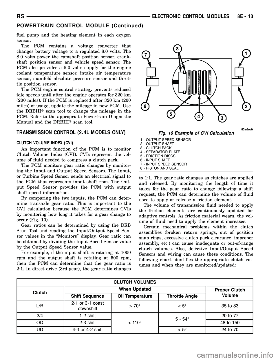
by monitoring how long it takes for a gear change to
occur (Fig. 10).
Gear ratios can be determined by using the DRB
Scan Tool and reading the Input/Output Speed Sen-
sor values in the ªMonitorsº display. Gear ratio can
be obtained by dividing the Input Speed Sensor value
by the Output Speed Sensor value.
For example, if the input shaft is rotating at 1000
rpm and the output shaft is rotating at 500 rpm,
then the PCM can determine that the gear ratio is
2:1. In direct drive (3rd gear), the gear ratio changesto 1:1. The gear ratio changes as clutches are applied
and released. By monitoring the length of time it
takes for the gear ratio to change following a shift
request, the PCM can determine the volume of fluid
used to apply or release a friction element.
The volume of transmission fluid needed to apply
the friction elements are continuously updated for
adaptive controls. As friction material wears, the vol-
ume of fluid need to apply the element increases.
Certain mechanical problems within the clutch
assemblies (broken return springs, out of position
snap rings, excessive clutch pack clearance, improper
assembly, etc.) can cause inadequate or out-of-range
clutch volumes. Also, defective Input/Output Speed
Sensors and wiring can cause these conditions. The
following chart identifies the appropriate clutch vol-
umes and when they are monitored/updated:
CLUTCH VOLUMES
ClutchWhen Updated
Proper Clutch
Volume
Shift Sequence Oil Temperature Throttle Angle
L/R2-1 or 3-1 coast
downshift>70É <5É 35to83
2/4 1-2 shift
> 110É5 - 54É20 to 77
OD 2-3 shift 48 to 150
UD 4-3 or 4-2 shift > 5É 24 to 70
Fig. 10 Example of CVI Calculation
1 - OUTPUT SPEED SENSOR
2 - OUTPUT SHAFT
3 - CLUTCH PACK
4 - SEPARATOR PLATE
5 - FRICTION DISCS
6 - INPUT SHAFT
7 - INPUT SPEED SENSOR
8 - PISTON AND SEAL
RSELECTRONIC CONTROL MODULES8E-13
POWERTRAIN CONTROL MODULE (Continued)