lock diagram CHRYSLER VOYAGER 2004 Owner's Guide
[x] Cancel search | Manufacturer: CHRYSLER, Model Year: 2004, Model line: VOYAGER, Model: CHRYSLER VOYAGER 2004Pages: 2585, PDF Size: 62.54 MB
Page 653 of 2585
and test again to be certain that the adjuster is not
at its travel limit. If the power seat track adjuster
still fails to operate in only one direction, refer to
Diagnosis and Testing Power Seat Switchin this
section. If the power seat track adjuster fails to oper-
ate in more than one direction, perform the following
tests. For complete circuit diagrams, refer to Wiring
Diagrams .
TESTING POWER SEAT TRACK MOTORS
(1) Check the power seat circuit breaker under the
seat. If OK, go to Step 2. If not OK, replace the
faulty power seat circuit breaker. (2) Check for battery voltage at the power seat cir-
cuit breaker under the seat. If OK, go to Step 3. If
not OK, repair the open fused B(+) circuit to the fuse
in the Intelligent Power Module as required. (3) Remove the outboard seat cushion side shield
from the seat. Disconnect the seat wire harness con-
nector from the power seat switch connector recepta-
cle. Check for battery voltage at the fused B(+)
circuit cavity of the power seat wire harness connec-
tor for the power seat switch. If OK, go to Step 4. If
not OK, repair the open fused B(+) circuit to the
power seat circuit breaker under the seat as
required. (4) Check for continuity between the ground cir-
cuit cavity of the power seat wire harness connector
for the power seat switch and a good ground. There
should be continuity. If OK, go to Step 5. If not OK,
repair the open ground circuit to ground as required. (5) Test the power seat switch. Refer to Diagnosis
and Testing Power Seat Switch in this section. If
the switch tests OK, test the circuits of the power
seat wire harness between the inoperative power seat
track adjuster motor and the power seat switch for
shorts or opens. If the circuits check OK, replace the
faulty power seat track unit. If the circuits are not
OK, repair the power seat wire harness as required.
REMOVAL
WARNING: SOME VEHICLES ARE EQUIPPED WITH
SEATBACK MOUNTED AIRBAGS. BEFORE
ATTEMPTING TO DIAGNOSE OR SERVICE ANY
SEAT OR POWER SEAT SYSTEM COMPONENT
YOU MUST FIRST DISCONNECT AND ISOLATE THE
BATTERY NEGATIVE CABLE. THEN WAIT TWO MIN-
UTES FOR THE SYSTEM CAPACITOR TO DIS-
CHARGE BEFORE FURTHER SYSTEM SERVICE.
THIS IS THE ONLY SURE WAY TO DISABLE THE
AIRBAG SYSTEM. FAILURE TO DO SO COULD
RESULT IN ACCIDENTAL AIRBAG DEPLOYMENT
AND POSSIBLE PERSONAL INJURY. (1) Remove the appropriate seat from the vehicle
and place it on a clean work surface(Refer to 23 -
BODY/SEATS/SEAT - REMOVAL). (2) If the vehicle is so equipped, remove the Mem-
ory Seat/Mirror Module (MSMM) retaining screws. (3) If the vehicle is so equipped, disconnect the
MSMM electrical connectors and remove the MSMM
from the power seat track. (4) Remove the rear fabric blocker trim panel from
the rear of the front seat. (5) Remove the seat side cover and power seat
switch as an assembly (Refer to 23 - BODY/SEATS/
SEAT CUSHION SIDE COVERS - REMOVAL). (6) Disconnect all electrical connectors connecting
the power seat track to the seat assembly. (7) Pull the seat back trim cover up slightly to
access and remove the two seat back frame mounting
bolts and also remove two seat back recliner bolts. (8) Remove four seat track mounting bolts from
the seat cushion pan. (9) Remove the power seat track from the seat.
INSTALLATION
(1) Position the seat cushion on the seat track.
(2) Install the four seat track retaining bolts in the
seat cushion pan. Torque the bolts to 28.5 N´m. (3) Position the seat back and install the two seat
back frame mounting bolts and the two seat back
recliner bolts. Torque the bolts to 55 N´m. (4) Route and connect the electrical connectors
between the power seat track and the seat assembly. (5) Install the seat side cover and power seat
switch as an assembly (Refer to 23 - BODY/SEATS/
SEAT CUSHION SIDE COVERS - INSTALLATION). (6) Install the rear fabric blocker trim panel on the
rear of the front seat. (7) If the vehicle is so equipped, position the Mem-
ory Seat/Mirror Module (MSMM) and connect the
MSMM electrical connectors. (8) Install the MSMM retaining screws.
(9) Install the seat assembly in the vehicle (Refer
to 23 - BODY/SEATS/SEAT - INSTALLATION).
PASSENGER POWER SEAT
TRACK
DESCRIPTION
The four-way passenger side power seat option
includes a electrically operated power seat track unit
located under the passenger side front seat. The
power seat circuit breaker is mounted on the rear of
the power seat track, just behind the seat rear trim
panel. The lower half of the power seat track is
secured to the floor panel via four studs and nuts
that must be accessed from the underside of the vehi-
8Ns - 16 POWER SEAT SYSTEMRS
DRIVER POWER SEAT TRACK (Continued)
Page 692 of 2585

CONDITION POSSIBLE CAUSES CORRECTION
WASHER SYSTEM WILL NOT
FLOW WASHER FLUID.1. NO WASHER FLUID IN
RESERVOIR.1. FILL WASHER RESERVOIR.
2. IPM FUSE #33 BLOWN. 2. SHORT OR DEFECTIVE CIRCUIT
BETWEEN IPM PIN 11 AND WASHER PUMP
MOTOR CONNECTOR POSITIVE TERMINAL
2. INTERNAL SHORT IN IPM. IF NOT OK,
REPAIR CIRCUIT OR REFER TO IPM
DIAGNOSTIC PROCEDURES IN WIRING
DIAGRAMS.
3. WASHER HOSE NOT
FLOWING WASHER FLUID.3. ASSURE WASHER HOSE IS NOT
PINCHED, LOOSE, BROKEN OR
DISCONNECTED. IF NOT OK, PROPERLY
ROUTE OR REPAIR WASHER HOSE.
4. MOTOR CONNECTOR LOOSE. 4. PROPERLY SEAT AND LOCK CONNECTOR
TO MOTOR.
5. MOTOR CONNECTOR
TERMINALS BENT.5. REPAIR TERMINALS AND PROPERLY
SEAT CONNECTOR TO MOTOR.
6. OPEN CIRCUIT TO OR FROM
WASHER SELECT SWITCH
(EXPORT AND ATC EQUIPPED
VEHICLES ONLY).6. OPEN OR DEFECTIVE CIRCUIT BETWEEN
IPM BODY CONTROLLER PIN 27 AND
WASHER SELECT SWITCH PIN 4, OR OPEN
OR DEFECTIVE CIRCUIT BETWEEN IPM
BODY CONTROLLER PIN 22 AND WASHER
SELECT SWITCH PIN 2. IF NOT OK, REPAIR
CIRCUIT.
7. OPEN OR DEFECTIVE
WASHER SELECT SWITCH.7. REFERO TO THE PROPER BODY
DIAGNOSTIC PROCEDURES INFORMATION
ON MANUAL TEMPERATURE CONTROLS.
8. OPEN POWER CIRCUIT TO
MOTOR.8. OPEN OR DEFECTIVE CIRCUIT BETWEEN
IPM CONNECTOR TERMINAL 11 AND
WASHER MOTOR CONNECTOR POSITIVE
TERMINAL 2. INTERNAL OPEN IN IPM. IF
NOT OK, REPAIR CIRCUIT OR REFER TO
IPM DIAGNOSTIC PROCEDURES IN WIRING
DIAGRAMS.
9. OPEN OR DEFECTIVE MOTOR
GROUND CIRCUIT.9. OPEN OR DEFECTIVE CIRCUIT BETWEEN
IPM CONNECTOR TERMINAL 20 AND
WASHER MOTOR CONNECTOR NEGATIVE
TERMINAL 1. INTERNAL OPEN IN IPM. IF
NOT OK, REPAIR CIRCUIT OR REFER TO
IPM DIAGNOSTIC PROCEDURES IN WIRING
DIAGRAMS.
10. OPEN CIRCUIT IN MOTOR. 10. CHECK FOR OPEN CIRCUIT IN MOTOR
BETWEEN POSITIVE TERMINAL 2 AND
NEGATIVE TERMINAL 1. IF NOT OK,
REPLACE WASHER MOTOR.
11. SEIZED MOTOR BEARINGS. 11. APPLY DIRECT BATTERY VOLTAGE TO
MOTOR TERMINALS. IF MOTOR DOES NOT
RUN, REPLACE MOTOR.
12. NO BUS MESSAGE FROM
MTC CONTROL (MANUAL TEMP.
CONTROL ONLY).12. CHECK FOR CORRECT PCI BUS
MESSAGE WITH DRBIIIT.
RSWIPERS/WASHERS8R-5
WIPERS/WASHERS (Continued)
Page 694 of 2585

CONDITION POSSIBLE CAUSES CORRECTION
WASHER OPERATES
INTERMITTENTLY.1. INTERMITTENT MOTOR
GROUND.INTERMITTENT GROUND BETWEEN MOTOR
CONNECTOR TERMINAL 1 AND IPM PIN 20.
2. INTERMITTENT OPEN IN
WASHER SELECT SWITCH.2. (Refer to 8 - ELECTRICAL/LAMPS/
LIGHTING - EXTERIOR/MULTI-FUNCTION
SWITCH - DIAGNOSIS AND TESTING).
3. DEFECTIVE WASHER MOTOR. 3. REPLACE WASHER MOTOR.
LOW WASHER FLUID LEVEL
INDICATOR INOPERATIVE.1. LOOSE FLUID LEVEL SENSOR
CONNECTOR.1. PROPERLY SEAT CONNECTOR TO LOW
FLUID LEVEL SENSOR AND LOCK.
2. OPEN POWER CIRCUIT TO
FLUID LEVEL SENSOR.2. OPEN OR DEFECTIVE CIRCUIT BETWEEN
IPM CONNECTOR TERMINAL 7 AND THE
LOW FLUID LEVEL SENSOR CONNECTOR
TERMINAL 2. IF NOT OK, REPAIR CIRCUIT.
3. OPEN GROUND CIRCUIT. 3. OPEN OR DEFECTIVE CIRCUIT BETWEEN
FLUID LEVEL SENSOR CONNECTOR
TERMINAL 1 AND FLOOR GROUND 1.
4. DEFECTIVE IPM. 4. REFER TO IPM DIAGNOSTIC
PROCEDURES IN WIRING DIAGRAMS.
5. FLUID LEVEL SENSOR
SWITCH OPEN OR DEFECTIVE.5. APPLY OHMMETER TO THE SWITCH
TERMINALS TO CHECK FOR COMPLETE
CIRCUIT. CYCLE SWITCH FLOAT BACK AND
FORTH BY FILLING AND DEPLETING
RESERVOIR OF WASHER FLUID TO CHECK
FOR PROPER SWITCH FUNCTION. IF NOT
OK, REPLACE LOW FLUID LEVEL SENSOR
SWITCH.
LEAKING WASHER FLUID. 1. PUMP OR SENSOR
GROMMET DEFECTIVE.1. PROPERLY SEAT PUMP OR SENSOR IN
GROMMET. IF NOT OK, REPLACE PUMP OR
SENSOR GROMMET.
2. LEAKING WASHER PUMP. 2. REPLACE WASHER PUMP.
3. LEAKING FLUID LEVEL
SENSOR.3. REPLACE FLUID LEVEL SENSOR.
4. LEAKING OR DEFECTIVE
RESERVOIR BODY.4. REPLACE RESERVOIR BODY.
RSWIPERS/WASHERS8R-7
WIPERS/WASHERS (Continued)
Page 704 of 2585
WIRING
TABLE OF CONTENTS
page page
WIRING DIAGRAM INFORMATION....... 8W-01-1
COMPONENT INDEX.................. 8W-02-1
POWER DISTRIBUTION............... 8W-10-1
GROUND DISTRIBUTION.............. 8W-15-1
BUS COMMUNICATIONS.............. 8W-18-1
CHARGING SYSTEM.................. 8W-20-1
STARTING SYSTEM.................. 8W-21-1
FUEL/IGNITION SYSTEM.............. 8W-30-1
TRANSMISSION CONTROL SYSTEM..... 8W-31-1
VEHICLE SPEED CONTROL............ 8W-33-1
ANTILOCK BRAKES................... 8W-35-1
VEHICLE THEFT SECURITY SYSTEM..... 8W-39-1
INSTRUMENT CLUSTER............... 8W-40-1
HORN/CIGAR LIGHTER/POWER OUTLET . . 8W-41-1
AIR CONDITIONING-HEATER........... 8W-42-1
AIRBAG SYSTEM.................... 8W-43-1
INTERIOR LIGHTING.................. 8W-44-1
BODY CONTROL MODULE............. 8W-45-1
MESSAGE CENTER................... 8W-46-1AUDIO SYSTEM..................... 8W-47-1
REAR WINDOW DEFOGGER............ 8W-48-1
OVERHEAD CONSOLE................. 8W-49-1
FRONT LIGHTING.................... 8W-50-1
REAR LIGHTING..................... 8W-51-1
TURN SIGNALS...................... 8W-52-1
WIPERS............................ 8W-53-1
TRAILER TOW....................... 8W-54-1
POWER WINDOWS................... 8W-60-1
POWER DOOR LOCKS................ 8W-61-1
POWER MIRRORS................... 8W-62-1
POWER SEATS...................... 8W-63-1
POWER SUNROOF................... 8W-64-1
SPLICE INFORMATION................ 8W-70-1
CONNECTOR PIN-OUTS............... 8W-80-1
CONNECTOR/GROUND/SPLICE
LOCATION........................ 8W-91-1
POWER DISTRIBUTION SYSTEM........ 8W-97-1 RSWIRING
8W-1
Page 713 of 2585

²Ohmmeter - Used to check the resistance
between two points of a circuit. Low or no resistance
in a circuit means good continuity.
CAUTION: Most of the electrical components used
in today's vehicles are Solid State. When checking
resistance in these circuits use a meter with a 10 -
megohm or greater impedance rating. In addition,
make sure the power is disconnected from the cir-
cuit. Circuits that are powered up by the vehicle's
electrical system can cause damage to the equip-
ment and provide false readings.
²Probing Tools - These tools are used for probing
terminals in connectors (Fig. 5). Select the proper
size tool from Special Tool Package 6807, and insert
it into the terminal being tested. Use the other end
of the tool to insert the meter probe.
INTERMITTENT AND POOR CONNECTIONS
Most intermittent electrical problems are caused
by faulty electrical connections or wiring. It is also
possible for a sticking component or relay to cause a
problem. Before condemning a component or wiring
assembly, check the following items.
²Connectors are fully seated
²Spread terminals, or terminal push out
²Terminals in the wiring assembly are fully
seated into the connector/component and locked into
position
²
Dirt or corrosion on the terminals. Any amount of
corrosion or dirt could cause an intermittent problem
²Damaged connector/component casing exposing
the item to dirt or moisture
²Wire insulation that has rubbed through causing
a short to ground
²Some or all of the wiring strands broken inside
of the insulation
²Wiring broken inside of the insulation
TROUBLESHOOTING WIRING PROBLEMS
When troubleshooting wiring problems there are
six steps which can aid in the procedure. The steps
are listed and explained below. Always check for non-factory items added to the vehicle before doing any
diagnosis. If the vehicle is equipped with these items,
disconnect them to verify these add-on items are not
the cause of the problem.
(1) Verify the problem.
(2) Verify any related symptoms. Do this by per-
forming operational checks on components that are
in the same circuit. Refer to the wiring diagrams.
(3) Analyze the symptoms. Use the wiring dia-
grams to determine what the circuit is doing, where
the problem most likely is occurring and where the
diagnosis will continue.
(4) Isolate the problem area.
(5) Repair the problem area.
(6) Verify the proper operation. For this step,
check for proper operation of all items on the
repaired circuit. Refer to the wiring diagrams.
STANDARD PROCEDURE
STANDARD PROCEDURE - ELECTROSTATIC
DISCHARGE (ESD) SENSITIVE DEVICES
All ESD sensitive components are solid state and a
symbol (Fig. 6) is used to indicate this. When han-
dling any component with this symbol, comply with
the following procedures to reduce the possibility of
electrostatic charge build up on the body and inad-
vertent discharge into the component. If it is not
known whether the part is ESD sensitive, assume
that it is.
(1) Always touch a known good ground before han-
dling the part. This should be repeated while han-
dling the part and more frequently after sliding
across a seat, sitting down from a standing position,
or walking a distance.
(2) Avoid touching electrical terminals of the part,
unless instructed to do so by a written procedure.
(3) When using a voltmeter, be sure to connect the
ground lead first.
(4) Do not remove the part form it's protective
packing until it is time to install the part.
(5) Before removing the part from it's pakage,
ground the pakage to a known good ground on the
vehicle.
Fig. 5 PROBING TOOL
1 - SPECIAL TOOL 6801
2 - PROBING END
Fig. 6 ELECTROSTATIC DISCHARGE SYMBOL
8W - 01 - 8 8W-01 WIRING DIAGRAM INFORMATIONRS
WIRING DIAGRAM INFORMATION (Continued)
Page 714 of 2585

STANDARD PROCEDURE - TESTING OF
VOLTAGE POTENTIAL
(1) Connect the ground lead of a voltmeter to a
known good ground (Fig. 7).
(2) Connect the other lead of the voltmeter to the
selected test point. The vehicle ignition may need to
be turned ON to check voltage. Refer to the appropri-
ate test procedure.
STANDARD PROCEDURE - TESTING FOR
CONTINUITY
(1) Remove the fuse for the circuit being checked
or, disconnect the battery.
(2) Connect one lead of the ohmmeter to one side
of the circuit being tested (Fig. 8).
(3) Connect the other lead to the other end of the
circuit being tested. Low or no resistance means good
continuity.
STANDARD PROCEDURE - TESTING FOR A
SHORT TO GROUND
(1) Remove the fuse and disconnect all items
involved with the fuse.
(2) Connect a test light or a voltmeter across the
terminals of the fuse.
(3) Starting at the fuse block, wiggle the wiring
harness about six to eight inches apart and watch
the voltmeter/test lamp.
(4) If the voltmeter registers voltage or the test
lamp glows, there is a short to ground in that gen-
eral area of the wiring harness.
Fig. 7 TESTING FOR VOLTAGE POTENTIAL
Fig. 8 TESTING FOR CONTINUITY
1 - FUSE REMOVED FROM CIRCUIT
RS8W-01 WIRING DIAGRAM INFORMATION8W-01-9
WIRING DIAGRAM INFORMATION (Continued)
Page 716 of 2585
CONNECTOR
REMOVAL
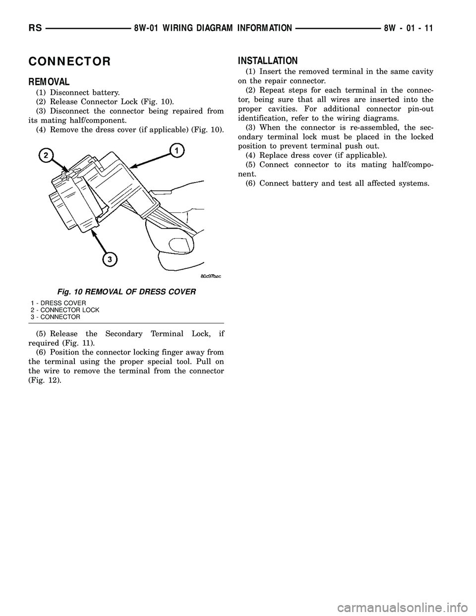
(1) Disconnect battery.
(2) Release Connector Lock (Fig. 10).
(3) Disconnect the connector being repaired from
its mating half/component.
(4) Remove the dress cover (if applicable) (Fig. 10).
(5) Release the Secondary Terminal Lock, if
required (Fig. 11).
(6) Position the connector locking finger away from
the terminal using the proper special tool. Pull on
the wire to remove the terminal from the connector
(Fig. 12).
INSTALLATION
(1) Insert the removed terminal in the same cavity
on the repair connector.
(2) Repeat steps for each terminal in the connec-
tor, being sure that all wires are inserted into the
proper cavities. For additional connector pin-out
identification, refer to the wiring diagrams.
(3) When the connector is re-assembled, the sec-
ondary terminal lock must be placed in the locked
position to prevent terminal push out.
(4) Replace dress cover (if applicable).
(5) Connect connector to its mating half/compo-
nent.
(6) Connect battery and test all affected systems.
Fig. 10 REMOVAL OF DRESS COVER
1 - DRESS COVER
2 - CONNECTOR LOCK
3 - CONNECTOR
RS8W-01 WIRING DIAGRAM INFORMATION8W-01-11
Page 717 of 2585
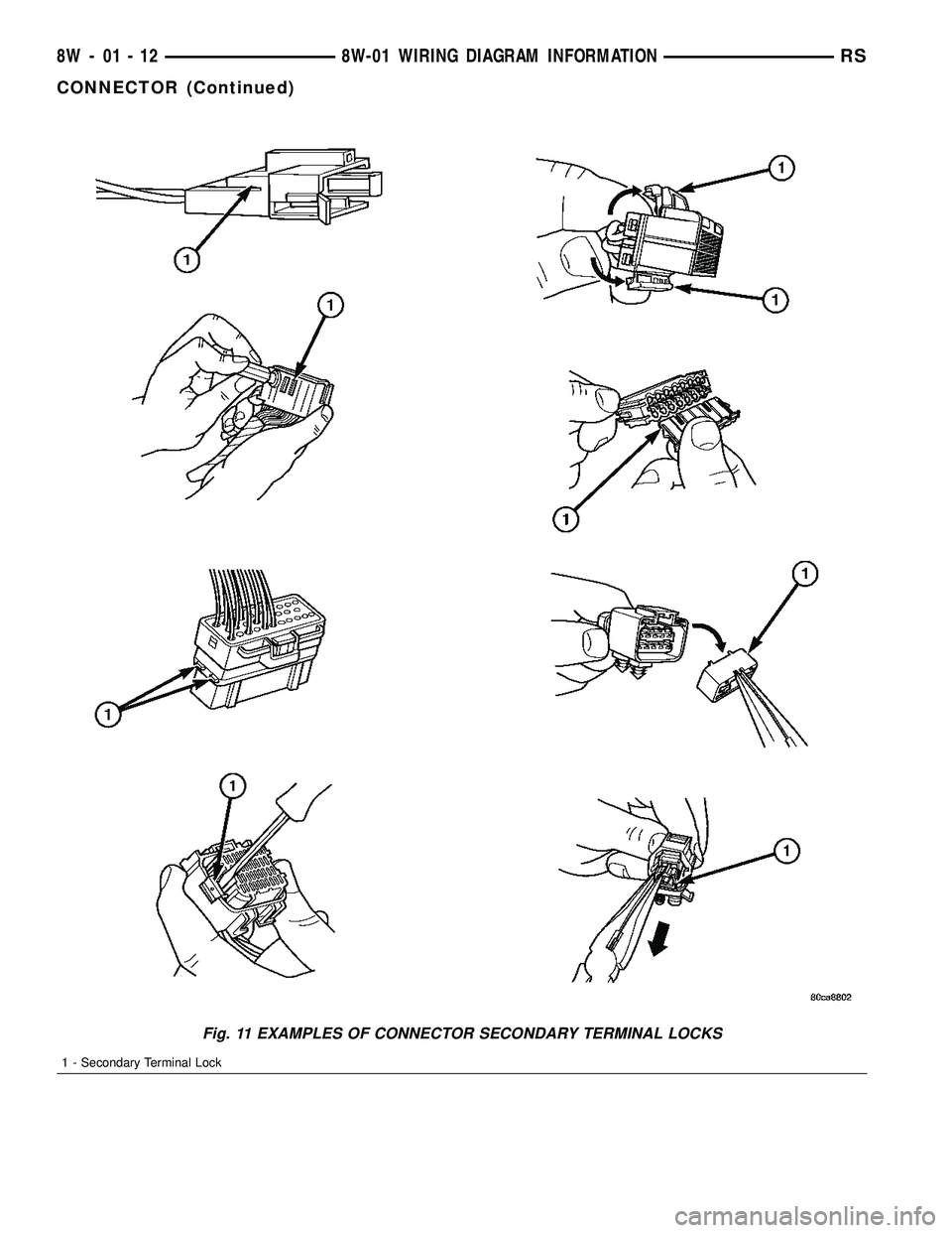
Fig. 11 EXAMPLES OF CONNECTOR SECONDARY TERMINAL LOCKS
1 - Secondary Terminal Lock
8W - 01 - 12 8W-01 WIRING DIAGRAM INFORMATIONRS
CONNECTOR (Continued)
Page 719 of 2585
DIODE
REMOVAL
(1) Disconnect the battery.
(2) Locate the diode in the harness, and remove
the protective covering.
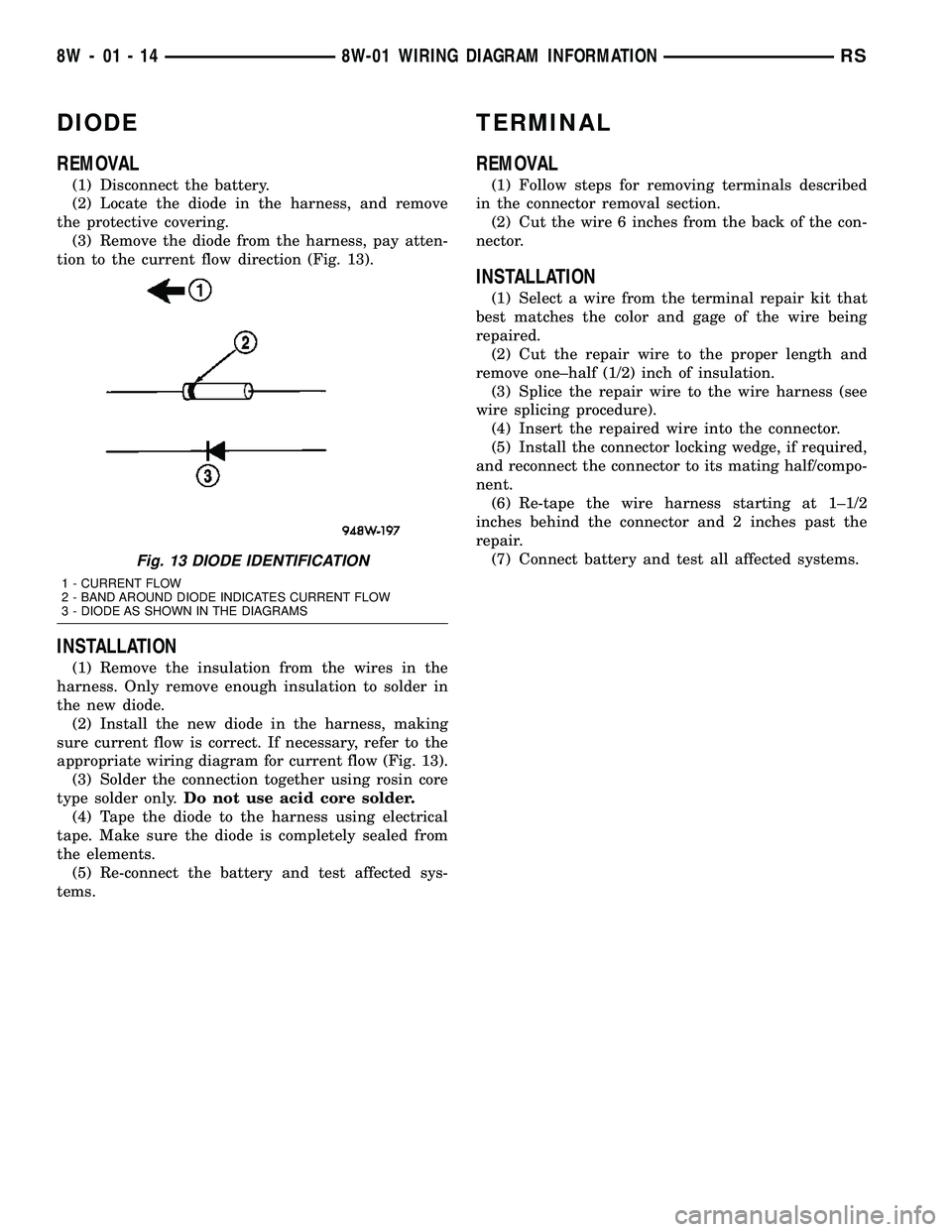
(3) Remove the diode from the harness, pay atten-
tion to the current flow direction (Fig. 13).
INSTALLATION
(1) Remove the insulation from the wires in the
harness. Only remove enough insulation to solder in
the new diode.
(2) Install the new diode in the harness, making
sure current flow is correct. If necessary, refer to the
appropriate wiring diagram for current flow (Fig. 13).
(3) Solder the connection together using rosin core
type solder only.Do not use acid core solder.
(4) Tape the diode to the harness using electrical
tape. Make sure the diode is completely sealed from
the elements.
(5) Re-connect the battery and test affected sys-
tems.
TERMINAL
REMOVAL
(1) Follow steps for removing terminals described
in the connector removal section.
(2) Cut the wire 6 inches from the back of the con-
nector.
INSTALLATION
(1) Select a wire from the terminal repair kit that
best matches the color and gage of the wire being
repaired.
(2) Cut the repair wire to the proper length and
remove one±half (1/2) inch of insulation.
(3) Splice the repair wire to the wire harness (see
wire splicing procedure).
(4) Insert the repaired wire into the connector.
(5) Install the connector locking wedge, if required,
and reconnect the connector to its mating half/compo-
nent.
(6) Re-tape the wire harness starting at 1±1/2
inches behind the connector and 2 inches past the
repair.
(7) Connect battery and test all affected systems.
Fig. 13 DIODE IDENTIFICATION
1 - CURRENT FLOW
2 - BAND AROUND DIODE INDICATES CURRENT FLOW
3 - DIODE AS SHOWN IN THE DIAGRAMS
8W - 01 - 14 8W-01 WIRING DIAGRAM INFORMATIONRS
Page 1292 of 2585
8W-97 POWER DISTRIBUTION SYSTEM
TABLE OF CONTENTS
page page
POWER DISTRIBUTION SYSTEM
DESCRIPTION..........................1
OPERATION............................1
SPECIAL TOOLS
POWER DISTRIBUTION SYSTEMS.........1
INTEGRATED POWER MODULE
DESCRIPTION..........................2
OPERATION............................2
REMOVAL.............................2
INSTALLATION..........................3IOD FUSE
DESCRIPTION..........................3
OPERATION............................3
POWER OUTLET
DESCRIPTION..........................4
OPERATION............................4
DIAGNOSIS AND TESTING
DIAGNOSIS & TESTING - POWER OUTLET . . 4
REMOVAL.............................5
INSTALLATION..........................5
POWER DISTRIBUTION
SYSTEM
DESCRIPTION
This group covers the various standard and
optional power distribution components used on this
model. The power distribution system for this vehicle
consists of the following components:
²Integrated Power Module (IPM)
²Front Control Module (FCM)
²Power Outlets
Refer to Wiring Diagrams for complete circuit sche-
matics.
The power distribution system also incorporates
various types of circuit control and protection fea-
tures, including:
²Automatic resetting circuit breakers
²Blade-type fuses
²Bus bars
²Cartridge fuses
²Circuit splice blocks
²Flashers
²Fusible links
²Relays
Following are general descriptions of the major
components in the power distribution system. See the
owner's manual in the vehicle glove box for more
information on the features and use of all of the
power distribution system components.
OPERATION
The power distribution system for this vehicle is
designed to provide safe, reliable, and centralized dis-
tribution points for the electrical current required to
operate all of the many standard and optional facto-
ry-installed electrical and electronic powertrain,
chassis, safety, security, comfort and convenience sys-
tems. At the same time, the power distribution sys-
tem was designed to provide ready access to these
electrical distribution points for the vehicle techni-
cian to use when conducting diagnosis and repair of
faulty circuits. The power distribution system can
also prove useful for the sourcing of additional elec-
trical circuits that may be required to provide the
electrical current needed to operate many accessories
that the vehicle owner may choose to have installed
in the aftermarket.
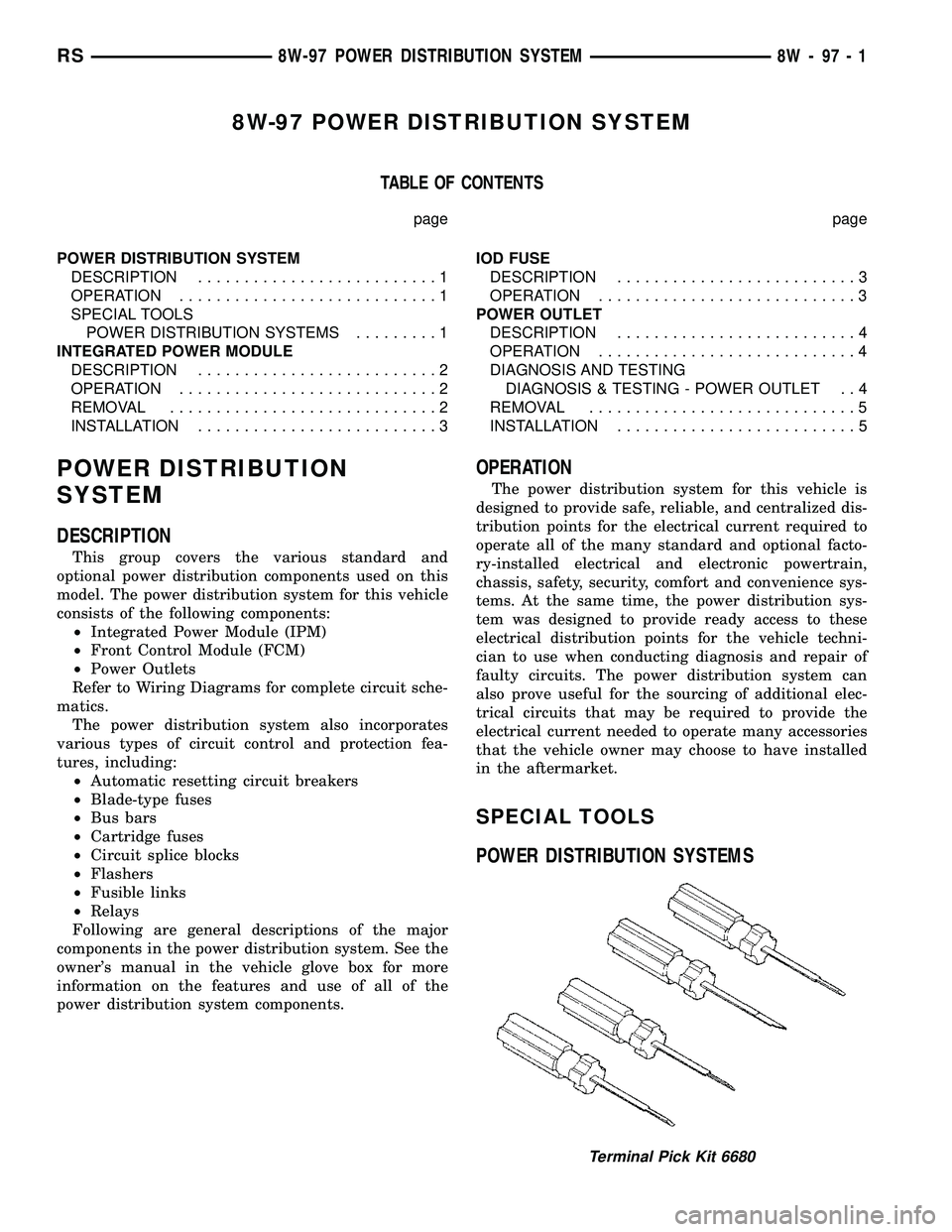
SPECIAL TOOLS
POWER DISTRIBUTION SYSTEMS
Terminal Pick Kit 6680
RS8W-97 POWER DISTRIBUTION SYSTEM8W-97-1