ESP CHRYSLER VOYAGER 2004 Workshop Manual
[x] Cancel search | Manufacturer: CHRYSLER, Model Year: 2004, Model line: VOYAGER, Model: CHRYSLER VOYAGER 2004Pages: 2585, PDF Size: 62.54 MB
Page 622 of 2585
The power seat system includes the following com-
ponents:
²Power seat recliners
²Power seat switches
²Power seat tracks
²Circuit breaker
The power seat system with memory and heated
seat options includes the following components:
²Power seat recliner
²Power seat switch
²Power seat track.
²Memory Seat Mirror Module (MSMM)
²Memory set switch
²Heated Seat Module (HSM)
²Heated seat switch
²Electronic Vehicle Information Center (EVIC)
²Programmable Communications Interface (PCI)
data bus network
Refer to Wiring Diagrams for complete circuit dia-
grams. Following are general descriptions and opera-
tions for the major components in the power seat
system and memory seat system.
DESCRIPTION - MEMORY SYSTEM
An electronic memory system is available on some
models. The memory system is able to store and
recall the driver side power seat positions (including
the power recliner position) and both outside side
view mirrors positions for two drivers. On vehicles
equipped with a factory radio, the memory system is
also able to store and recall radio station presets fortwo drivers. The memory system also will store and
recall the last station listened to for each driver, even
if it is not one of the preset stations.
The memory system will automatically return to
its preset settings when the corresponding numbered
button of the memory switch is depressed, or when
the doors are unlocked using the corresponding
Remote Keyless Entry (RKE) transmitter. A customer
programmable feature of the memory system allows
the RKE recall of memory features to be disabled, if
desired. This programmable feature is internal in the
EVIC module, which is located in the overhead con-
sole.
A Memory Seat Mirror Module (MSMM) is used on
some models to control and integrate the many elec-
tronic functions and features included in the memory
seat and mirror systems.
The memory system includes the following compo-
nents:
²Memory Seat Mirror Module (MSMM)
²Memory set switch
²Position potentiometers on both outside side
view mirrors
²Position potentiometers on the driver side power
seat track and power seat recliner motors.
²Electronic Vehicle Information Center (EVIC)
²Radio receiver (if PCI data bus capable).
Certain functions of the memory system rely upon
resources shared with other electronic modules in the
vehicle over the Programmable Communications
Interface (PCI) J1850 data bus network. The PCI
data bus network allows the sharing of sensor infor-
mation. This helps to reduce wire harness complexity,
internal controller hardware, and component sensor
current loads. At the same time, this system provides
increased reliability, enhanced diagnostics, and
allows the addition of many new feature capabilities.
Initial diagnosis of these electronic modules or the
PCI data bus network requires the use of a DRBIIIt
scan tool and the proper Diagnostic Procedures man-
ual. If this method does not prove conclusive, the use
of a automotive meter such as the Fluket, the proper
wiring schematics and the service manual diagnostic
routines are required.
The other electronic modules that may affect mem-
ory system operation are as follows:
²Body Control Module (BCM)- Refer toBody
Control Modulein Electronic Control Modules for
more information.
²Powertrain Control Module (PCM)- Refer to
Powertrain Control Modulein Electronic Control
Modules for more information.
²Transmission Control Module (TCM)- Refer
toTransmission Control Modulein Electronic
Control Modules for more information.
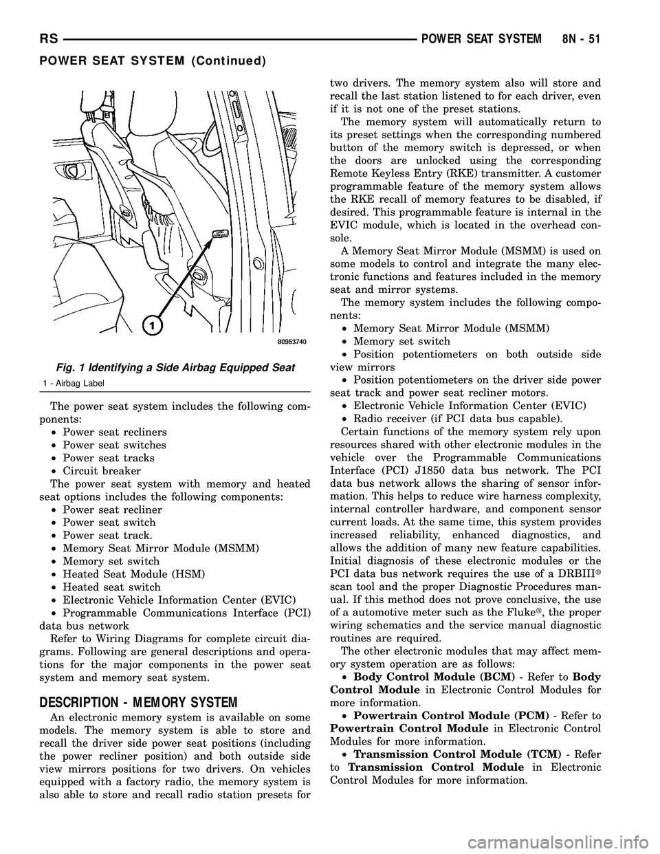
Fig. 1 Identifying a Side Airbag Equipped Seat
1 - Airbag Label
RSPOWER SEAT SYSTEM8N-51
POWER SEAT SYSTEM (Continued)
Page 623 of 2585
Refer toHeated Seat Systemfor more informa-
tion on the heated seat system. Refer toRemote
Keyless Entry Systemin Power Lock Systems for
more information on the RKE system.
Refer toWiring Diagramsfor complete circuit
diagrams. Following are descriptions, theory of oper-
ation, diagnosis/testing procedures and removal/in-
stallation procedures of the major components in the
memory and power seat systems.
OPERATION
OPERATION - POWER SEAT SYSTEM
The power seat system receives battery current
through fuse #22 in the Intelligent Power Module
and a circuit breaker under the front seats, regard-
less of the ignition switch position.
When a power seat switch control knob or knobs
are actuated, a battery feed and a ground path are
applied through the switch contacts to the appropri-
ate power seat track adjuster motor. The selected
adjuster motor operates to move the seat track
through its drive unit in the selected direction until
the switch is released, or until the travel limit of the
seat track is reached. When the switch is moved in
the opposite direction, the battery feed and ground
path to the motor are reversed through the switch
contacts. This causes the adjuster motor to run in the
opposite direction.
No power seat switch should be held applied in any
direction after the seat track has reached its travel
limit. The power seat track each contain a self-reset-
ting circuit breaker to protect them from overload.
However, consecutive or frequent resetting of the cir-
cuit breaker must not be allowed to continue, or the
motor may be damaged. Refer to the owner's manual
in the vehicle glove box for more information on the
features, use and operation of the power seat system.
OPERATION - MEMORY SYSTEM
The Memory Seat Mirror Module (MSMM) receives
battery current through fuse #22 in the Intelligent
Power Module and the power seat system circuit
breaker, located under the driver side front seat near
the rear edge of the seat cushion pan. The memory
system does not operate with the Ignition-Off Draw
(IOD) fuse removed. The MSMM will drive a maxi-
mum of 2 motors at a time in a given direction. If
conflicting directions are requested, the priority for
response will be approximately as follows:
²Seat Track Rearward or Forward
²Seat Front Down or Up
²Seat Rear Down or Up
²Recliner Rearward or ForwardThe inputs from these switches to the MSMM is a
current limited battery source fed by the MSMM.
This protects the MSMM printed circuit board traces
from acting as fuses. All of these switch contact
inputs to the MSMM are normally closed to ground,
except when actuated.
See the owner's manual in the vehicle glove box for
more information on the features, use and operation
of the memory system. For diagnosis of the MSMM,
the PCI data bus, or the other electronic modules on
the PCI data bus that provide inputs and outputs for
the memory system, the use of a DRBIIItscan tool
and the proper Diagnostic Procedures manual are
recommended.
ELECTRONIC VEHICLE INFORMATION CENTER
The Electronic Vehicle Information Center (EVIC)
serves as the user interface for the memory system.
It displays memory system status messages and pro-
vides the user with the means for enabling and dis-
abling the many customer programmable features
available on the vehicle, including those for the mem-
ory system.
See the owner's manual in the vehicle glove box for
more information on the features, use and operation
of the EVIC. Refer toElectronic Vehicle Informa-
tion Centerin Overhead Console Systems for more
information on the EVIC.
DIAGNOSIS AND TESTING
DIAGNOSIS AND TESTING - POWER SEAT
SYSTEM
Following are tests that will help to diagnose the
hard wired components and circuits of the power seat
system. However, if the vehicle is also equipped with
the optional memory system, these tests may not
prove conclusive in the diagnosis of the driver side
power seat. In order to obtain conclusive testing of
the driver side power seat with the memory system
option, the Programmable Communications Interface
(PCI) data bus network and all of the electronic mod-
ules that provide inputs to, or receive outputs from
the memory system components must be checked.
The most reliable, efficient, and accurate means to
diagnose the driver side power seat with the memory
system option requires the use of a DRBIIItscan tool
and the proper Diagnostic Procedures manual. The
DRBIIItscan tool can provide confirmation that the
PCI data bus is functional, that all of the electronic
modules are sending and receiving the proper mes-
sages on the PCI data bus, and that the memory sys-
tem is receiving the proper hard wired inputs and
relaying the proper hard wired outputs to perform its
driver side power seat functions.
8N - 52 POWER SEAT SYSTEMRS
POWER SEAT SYSTEM (Continued)
Page 645 of 2585
The power seat system includes the following com-
ponents: ² Power seat recliners
² Power seat switches
² Power seat tracks
² Circuit breaker
The power seat system with memory and heated
seat options includes the following components: ² Power seat recliner
² Power seat switch
² Power seat track.
² Memory Seat Mirror Module (MSMM)
² Memory set switch
² Heated Seat Module (HSM)
² Heated seat switch
² Electronic Vehicle Information Center (EVIC)
² Programmable Communications Interface (PCI)
data bus network Refer to Wiring Diagrams for complete circuit dia-
grams. Following are general descriptions and opera-
tions for the major components in the power seat
system and memory seat system.
DESCRIPTION - MEMORY SYSTEM
An electronic memory system is available on some
models. The memory system is able to store and
recall the driver side power seat positions (including
the power recliner position) and the driver outside
side view mirror position for two drivers. On vehicles
equipped with a factory radio, the memory system is also able to store and recall radio station presets for
two drivers. The memory system also will store and
recall the last station listened to for each driver, even
if it is not one of the preset stations.
The memory system will automatically return to
its preset settings when the corresponding numbered
button of the memory switch is depressed, or when
the doors are unlocked using the corresponding
Remote Keyless Entry (RKE) transmitter. A customer
programmable feature of the memory system allows
the RKE recall of memory features to be disabled, if
desired. This programmable feature is internal in the
EVIC module, which is located in the overhead con-
sole. A Memory Seat Mirror Module (MSMM) is used to
control and integrate the many electronic functions
and features included in the memory seat and mirror
systems. The memory system includes the following compo-
nents: ² Memory Seat Mirror Module (MSMM)
² Memory set switch
² Position potentiometers on the driver outside
side view mirror ² Position potentiometers on the driver side power
seat track and power seat recliner motors. ² Electronic Vehicle Information Center (EVIC)
² Radio receiver (if PCI data bus capable).
Certain functions of the memory system rely upon
resources shared with other electronic modules in the
vehicle over the Programmable Communications
Interface (PCI) J1850 data bus network. The PCI
data bus network allows the sharing of sensor infor-
mation. This helps to reduce wire harness complexity,
internal controller hardware, and component sensor
current loads. At the same time, this system provides
increased reliability, enhanced diagnostics, and
allows the addition of many new feature capabilities.
Initial diagnosis of these electronic modules or the
PCI data bus network requires the use of a DRBIII t
scan tool and the proper Diagnostic Procedures man-
ual. If this method does not prove conclusive, the use
of a automotive meter such as the Fluke t, the proper
wiring schematics and the service manual diagnostic
routines are required. The other electronic modules that may affect mem-
ory system operation are as follows: ² Body Control Module (BCM) - Refer toBody
Control Module in Electronic Control Modules for
more information. ² Powertrain Control Module (PCM) - Refer to
Powertrain Control Module in Electronic Control
Modules for more information. ² Transmission Control Module (TCM) - Refer
to Transmission Control Module in Electronic
Control Modules for more information.
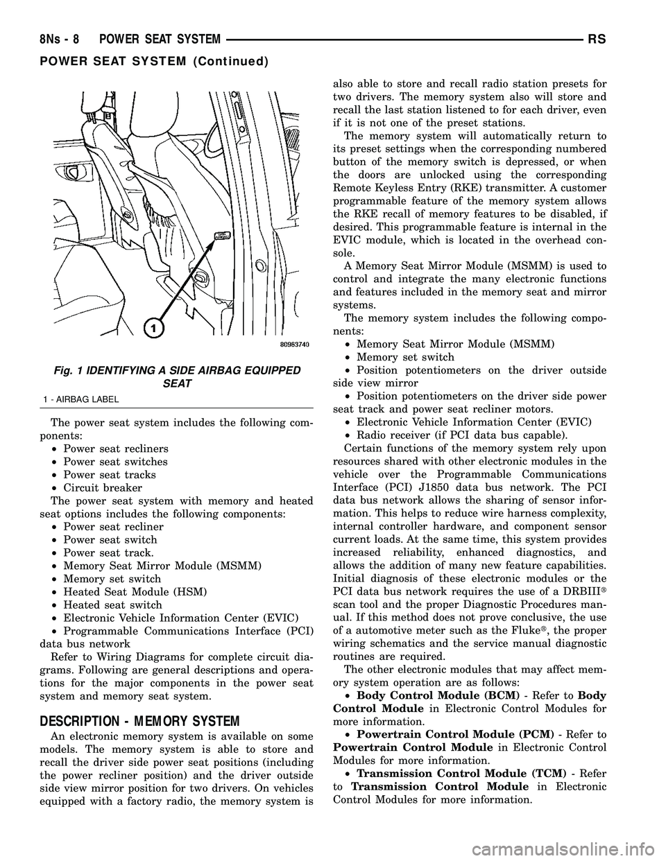
Fig. 1 IDENTIFYING A SIDE AIRBAG EQUIPPED SEAT
1 - AIRBAG LABEL
8Ns - 8 POWER SEAT SYSTEMRS
POWER SEAT SYSTEM (Continued)
Page 646 of 2585
Refer toHeated Seat System for more informa-
tion on the heated seat system. Refer to Remote
Keyless Entry System in Power Lock Systems for
more information on the RKE system. Refer to Wiring Diagrams for complete circuit
diagrams. Following are descriptions, theory of oper-
ation, diagnosis/testing procedures and removal/in-
stallation procedures of the major components in the
memory and power seat systems.
OPERATION
OPERATION - POWER SEAT SYSTEM
The power seat system receives battery current
through fuse #22 in the Intelligent Power Module
and a circuit breaker under the front seats, regard-
less of the ignition switch position. When a power seat switch control knob or knobs
are actuated, a battery feed and a ground path are
applied through the switch contacts to the appropri-
ate power seat track adjuster motor. The selected
adjuster motor operates to move the seat track
through its drive unit in the selected direction until
the switch is released, or until the travel limit of the
seat track is reached. When the switch is moved in
the opposite direction, the battery feed and ground
path to the motor are reversed through the switch
contacts. This causes the adjuster motor to run in the
opposite direction. No power seat switch should be held applied in any
direction after the seat track has reached its travel
limit. The power seat track each contain a self-reset-
ting circuit breaker to protect them from overload.
However, consecutive or frequent resetting of the cir-
cuit breaker must not be allowed to continue, or the
motor may be damaged. Refer to the owner's manual
in the vehicle glove box for more information on the
features, use and operation of the power seat system.
OPERATION - MEMORY SYSTEM
The Memory Seat Mirror Module (MSMM) receives
battery current through fuse #22 in the Intelligent
Power Module and the power seat system circuit
breaker, located under the driver side front seat near
the rear edge of the seat cushion pan. The memory
system does not operate with the Ignition-Off Draw
(IOD) fuse removed. The MSMM will drive a maxi-
mum of 2 motors at a time in a given direction. If
conflicting directions are requested, the priority for
response will be approximately as follows: ² Seat Track Rearward or Forward
² Seat Front Down or Up
² Seat Rear Down or Up
² Recliner Rearward or Forward The inputs from these switches to the MSMM is a
current limited battery source fed by the MSMM.
This protects the MSMM printed circuit board traces
from acting as fuses. All of these switch contact
inputs to the MSMM are normally closed to ground,
except when actuated. See the owner's manual in the vehicle glove box for
more information on the features, use and operation
of the memory system. For diagnosis of the MSMM,
the PCI data bus, or the other electronic modules on
the PCI data bus that provide inputs and outputs for
the memory system, the use of a DRBIII tscan tool
and the proper Diagnostic Procedures manual are
recommended.
ELECTRONIC VEHICLE INFORMATION CENTER
The Electronic Vehicle Information Center (EVIC)
serves as the user interface for the memory system.
It displays memory system status messages and pro-
vides the user with the means for enabling and dis-
abling the many customer programmable features
available on the vehicle, including those for the mem-
ory system. See the owner's manual in the vehicle glove box for
more information on the features, use and operation
of the EVIC. Refer to Electronic Vehicle Informa-
tion Center in Overhead Console Systems for more
information on the EVIC.
DIAGNOSIS AND TESTING
DIAGNOSIS AND TESTING - POWER SEAT
SYSTEM
Following are tests that will help to diagnose the
hard wired components and circuits of the power seat
system. However, if the vehicle is also equipped with
the optional memory system, these tests may not
prove conclusive in the diagnosis of the driver side
power seat. In order to obtain conclusive testing of
the driver side power seat with the memory system
option, the Programmable Communications Interface
(PCI) data bus network and all of the electronic mod-
ules that provide inputs to, or receive outputs from
the memory system components must be checked. The most reliable, efficient, and accurate means to
diagnose the driver side power seat with the memory
system option requires the use of a DRBIII tscan tool
and the proper Diagnostic Procedures manual. The
DRBIII tscan tool can provide confirmation that the
PCI data bus is functional, that all of the electronic
modules are sending and receiving the proper mes-
sages on the PCI data bus, and that the memory sys-
tem is receiving the proper hard wired inputs and
relaying the proper hard wired outputs to perform its
driver side power seat functions.
RS POWER SEAT SYSTEM8Ns-9
POWER SEAT SYSTEM (Continued)
Page 659 of 2585
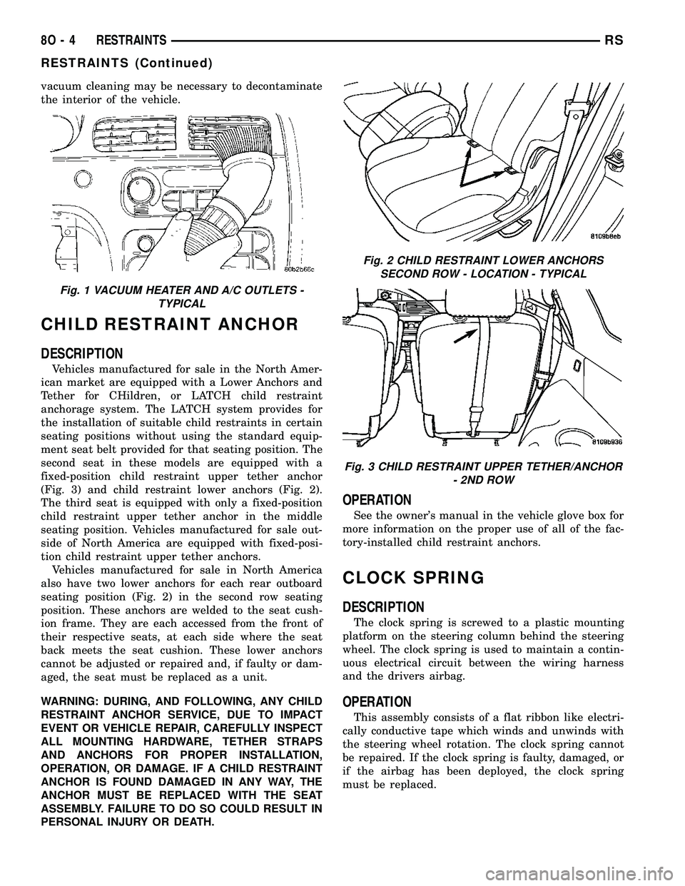
vacuum cleaning may be necessary to decontaminate
the interior of the vehicle.
CHILD RESTRAINT ANCHOR
DESCRIPTION
Vehicles manufactured for sale in the North Amer-
ican market are equipped with a Lower Anchors and
Tether for CHildren, or LATCH child restraint
anchorage system. The LATCH system provides for
the installation of suitable child restraints in certain
seating positions without using the standard equip-
ment seat belt provided for that seating position. The
second seat in these models are equipped with a
fixed-position child restraint upper tether anchor
(Fig. 3) and child restraint lower anchors (Fig. 2).
The third seat is equipped with only a fixed-position
child restraint upper tether anchor in the middle
seating position. Vehicles manufactured for sale out-
side of North America are equipped with fixed-posi-
tion child restraint upper tether anchors.
Vehicles manufactured for sale in North America
also have two lower anchors for each rear outboard
seating position (Fig. 2) in the second row seating
position. These anchors are welded to the seat cush-
ion frame. They are each accessed from the front of
their respective seats, at each side where the seat
back meets the seat cushion. These lower anchors
cannot be adjusted or repaired and, if faulty or dam-
aged, the seat must be replaced as a unit.
WARNING: DURING, AND FOLLOWING, ANY CHILD
RESTRAINT ANCHOR SERVICE, DUE TO IMPACT
EVENT OR VEHICLE REPAIR, CAREFULLY INSPECT
ALL MOUNTING HARDWARE, TETHER STRAPS
AND ANCHORS FOR PROPER INSTALLATION,
OPERATION, OR DAMAGE. IF A CHILD RESTRAINT
ANCHOR IS FOUND DAMAGED IN ANY WAY, THE
ANCHOR MUST BE REPLACED WITH THE SEAT
ASSEMBLY. FAILURE TO DO SO COULD RESULT IN
PERSONAL INJURY OR DEATH.
OPERATION
See the owner's manual in the vehicle glove box for
more information on the proper use of all of the fac-
tory-installed child restraint anchors.
CLOCK SPRING
DESCRIPTION
The clock spring is screwed to a plastic mounting
platform on the steering column behind the steering
wheel. The clock spring is used to maintain a contin-
uous electrical circuit between the wiring harness
and the drivers airbag.
OPERATION
This assembly consists of a flat ribbon like electri-
cally conductive tape which winds and unwinds with
the steering wheel rotation. The clock spring cannot
be repaired. If the clock spring is faulty, damaged, or
if the airbag has been deployed, the clock spring
must be replaced.
Fig. 1 VACUUM HEATER AND A/C OUTLETS -
TYPICAL
Fig. 2 CHILD RESTRAINT LOWER ANCHORS
SECOND ROW - LOCATION - TYPICAL
Fig. 3 CHILD RESTRAINT UPPER TETHER/ANCHOR
- 2ND ROW
8O - 4 RESTRAINTSRS
RESTRAINTS (Continued)
Page 672 of 2585
(10) Connect speaker connector. The left side has
the speaker mounted in the D-pillar trim cover and
the right side will have the speaker mounted in the
rear of the quarter trim panel, but the connector is
accessible from the rear after the D-pillar trim is
removed.
(11) Install D-pillar trim cover.
(12) Install second seat belt lower anchor bolt.
Torque bolt to 39 N´m (29 ft. lbs.).
(13) Install second seat belt upper turning loop
anchor bolt. Torque bolt to 39 N´m (29 ft. lbs.).
(14) Install upper liftgate trim.
(15) Install liftgate sill plate.
(16) Install first row seat belt upper turning loop
anchor bolt. Torque bolt to 39 N´m (29 ft. lbs.).
(17) Install first row seat belt lower anchor bolt.
Torque bolt to 39 N´m (29 ft. lbs.).
(18) Install first and second row seats.
SEAT BELT & RETRACTOR -
SECOND ROW - LEFT
OUTBOARD
REMOVAL
(1) Remove first and second row seats.
(2) Remove first row seat belt lower anchor bolt.
(3) Remove first row seat belt upper anchor bolt.
(4) Remove liftgate sill plate.
(5) Remove upper liftgate trim.
(6) Remove second seat belt lower anchor bolt.
(7) Remove second seat belt upper anchor bolt.
(8) Remove D-pillar trim cover.
(9) Disconnect speaker connector. The left side has
the speaker mounted in the D-pillar trim cover and
the right side will have the speaker mounted in the
rear of the quarter trim panel, but the connector is
accessible from the rear after the D-pillar trim is
removed.
(10) Remove quarter trim bolster.
(11) Remove quarter trim panel screws.
(12) Remove quarter trim panel.
(13) Remove retractor retaining bolt.
(14) Remove second row seat belt and retractor
from vehicle.
INSTALLATION
(1) Install second row seat belt and retractor.
Torque bolt to 39 N´m (29 ft. lbs.).
(2) Install quarter trim panel.
(3) Install quarter trim panel screws.
(4) Install quarter trim bolster.
(5) Connect speaker connector. The left side has
the speaker mounted in the D-pillar trim cover andthe right side will have the speaker mounted in the
rear of the quarter trim panel, but the connector is
accessible from the rear after the D-pillar trim is
removed.
(6) Install D-pillar trim cover.
(7) Install second seat belt lower anchor bolt.
Torque bolt to 39 N´m (29 ft. lbs.).
(8) Install second seat belt upper turning loop
anchor bolt. Torque bolt to 39 N´m (29 ft. lbs.).
(9) Install upper liftgate trim.
(10) Install liftgate sill plate.
(11) Install first row seat belt upper turning loop
anchor bolt. Torque bolt to 39 N´m (29 ft. lbs.).
(12) Install first row seat belt lower anchor bolt.
Torque bolt to 39 N´m (29 ft. lbs.).
(13) Install first and second row seats.
SEAT BELT TENSIONER
DESCRIPTION
The seat belt system incorporates Seat Belt Ten-
sioners. The tensioner is designed to hold the occu-
pant in their respective seat by retracting the seat
belt up to four inches. They are integral to the front
seat belt buckles and cannot be serviced. If found
defective they must be replaced. After an airbag
deployment, the tensioner must be replaced.
OPERATION
At the onset of an impact event, each tensioner
uses a pyrotechnic device which is triggered simulta-
neously with the airbags to rapidly retract the seat
belts. With the slack removed, the occupant's forward
motion in an impact will be reduced as will the like-
lihood of contacting interior components. After an
impact that deploys the airbags, the seat belt ten-
sioner assembly must be replaced.
The Occupant Restraint Controller (ORC) monitors
the seat belt tensioner circuit resistance and reports
active and stored Diagnostic Trouble Codes (DTC's) if
any problem is found.
Once a vehicle has been in an accident, the ten-
sioner must be replaced along with any deployed air-
bags and broken or damaged parts. Refer to the
proper Body Diagnostic Procedures manual for diag-
nosis and testing.
WARNING: WHEN THE FRONT AIRBAG IS
DEPLOYED, THE TENSIONER WILL HAVE
DEPLOYED ALSO AND SHOULD BE REPLACED.
FAILURE TO DO SO COULD RESULT IN OCCUPANT
PERSONAL INJURY OR DEATH.
RSRESTRAINTS8O-17
SEAT BELT & RETRACTOR - SECOND ROW - RIGHT OUTBOARD WITH REAR HVAC - LWB (Continued)
Page 676 of 2585
AUTOMATIC SPEED CONTROL OVERSPEED
REDUCTION
DESCRIPTION
Transmission control software includes an auto-
matic speed control overspeed reduction feature. This
maintains vehicle speed at the selected set point
when descending a grade.
OPERATION
The TCM (on SBEC vehicles) (PCM on NGC vehi-
cles) first senses that the speed control is set. If the
set speed is exceeded by more than 4 mph (6.5
km/hr) and the throttle is closed, the TCM (on SBEC
vehicles) (PCM on NGC vehicles) causes the trans-
axle to downshift to THIRD gear. After downshifting,
the automatic speed control resumes normal opera-
tion. To ensure that an upshift is appropriate after
the set speed is reached, the TCM (on SBEC vehi-
cles) (PCM on NGC vehicles) waits until the speed
control system opens the throttle at least 6 degrees
before upshifting to OVERDRIVE again.
If the driver applies the brakes, canceling auto-
matic speed control operation with the transaxle still
in THIRD gear, the TCM (on SBEC vehicles) (PCM
on NGC vehicles) maintains this gear until the driver
opens the throttle at least 6 degrees to avoid an inap-
propriate upshift. The upshift is also delayed for 2.5
seconds after reaching the 6 degrees throttle opening
in anticipation that the driver might open the throt-
tle enough to require THIRD gear. This will avoid
unnecessary and disturbing transmission cycling. If
the automatic speed control RESUME feature is used
after braking, the upshift is delayed until the set
speed is achieved to reduce cycling and provide bet-
ter response.
DIAGNOSIS AND TESTING - ROAD TEST
Perform a vehicle road test to verify reports of
speed control system malfunction. The road test
should include attention to the speedometer. Speed-
ometer operation should be smooth and without flut-
ter at all speeds.
Flutter in the speedometer indicates a problem
which might cause surging in the speed control sys-
tem. The cause of any speedometer problems should
be corrected before proceeding. Refer to the Instru-
ment Cluster for speedometer diagnosis.
If a road test verifies an inoperative system, and
the speedometer operates properly, check for:
²A Diagnostic Trouble Code (DTC). If a DTC
exists, conduct tests per the Powertrain Diagnostic
Procedures manual.
²A misadjusted brake (stop) lamp switch. This
could also cause an intermittent problem.
²Loose or corroded electrical connections at the
servo. Corrosion should be removed from electrical
terminals and a light coating of Mopar Multipurpose
Grease, or equivalent, applied.
²Leaking vacuum reservoir.
²Loose or leaking vacuum hoses or connections.
²Defective one-way vacuum check valve.
²Secure attachment at both ends of the speed
control servo cable.
²Smooth operation of throttle linkage and throttle
body air valve.
²Conduct electrical test at PCM.
²Failed speed control servo. Do the servo vacuum
test.
CAUTION: When test probing for voltage or conti-
nuity at electrical connectors, care must be taken
not to damage connector, terminals or seals. If
these components are damaged, intermittent or
complete system failure may occur.
SPECIFICATIONS - TORQUE
DESCRIPTION N´m Ft. Lbs. In. Lbs.
Servo Mounting Bracket
Nuts14 10.3 123.9
Servo Mounting Bracket
Bolts14 10.3 123.9
Servo Mounting Nuts 6.7 60
RSSPEED CONTROL8P-3
SPEED CONTROL (Continued)
Page 677 of 2585
CABLE
DESCRIPTION
The speed control servo cable is connected between
the speed control vacuum servo diaphragm and the
throttle body control linkage.
OPERATION
This cable causes the throttle control linkage to
open or close the throttle valve in response to move-
ment of the vacuum servo diaphragm.
REMOVAL
(1) Disconnect the negative battery cable.
(2) Remove speed control cable from throttle cam
by sliding clasp out hole used for throttle cable.
(3) Compress the retaining tabs on the cable and
slide cable out of bracket.
(4) Disconnect electrical connectors and vacuum
hose from servo.
(5) Remove two nuts attaching speed control cable
and mounting bracket to servo.
(6) Pull cable away from servo to expose retaining
clip and remove clip attaching cable to servo.
(7) Remove speed control cable.
INSTALLATION
(1) Slide cable into throttle cable bracket and
engage retaining tabs.
(2) Rotate the throttle cam forward to the wide
open position and install speed control cable clasp.
(3) Rotate the throttle cam forward to the wide
open position and install throttle cable clasp.
(4) Install retaining clip that attaches cable to
servo.
(5) Insert servo studs through holes in the mount-
ing bracket and speed control cable.
(6) Install nuts, tighten to 6.7 N´m (60 in. lbs.).
(7) Connect vacuum hose to servo.
(8) Connect electrical connector.
(9) Install servo and bracket and tighten nuts and
bolt.
(10) Connect negative battery cable.
SERVO
DESCRIPTION
The servo unit consists of a solenoid valve body,
and a vacuum chamber. The solenoid valve body con-
tains three solenoids:
²Vacuum
²Vent
²Dump
The vacuum chamber contains a diaphragm with a
cable attached to control the throttle linkage.
OPERATION
The PCM controls the solenoid valve body. The
solenoid valve body controls the application and
release of vacuum to the diaphragm of the vacuum
servo. The servo unit cannot be repaired and is ser-
viced only as a complete assembly.
Power is supplied to the servo by the PCM through
the brake switch. The PCM controls the ground path
for the vacuum and vent solenoids.
The dump solenoid is energized anytime it receives
power. If power to the dump solenoid is interrupted,
the solenoid dumps vacuum in the servo. This pro-
vides a safety backup to the vent and vacuum sole-
noids.
The vacuum and vent solenoids must be grounded
by the PCM to operate. When the PCM grounds the
vacuum servo solenoid, the solenoid allows vacuum
to enter the servo and pull open the throttle plate
using the cable. When the PCM breaks the ground,
the solenoid closes and no more vacuum is allowed to
enter the servo. The PCM also operates the vent sole-
noid via ground. The vent solenoid opens and closes a
passage to bleed or hold vacuum in the servo as
required.
The PCM cycles the vacuum and vent solenoids to
maintain the set speed, or to accelerate and deceler-
ate the vehicle. To increase throttle opening, the
PCM grounds the vacuum and vent solenoids. To
decrease throttle opening, the PCM removes the
grounds from the vacuum and vent solenoids.
8P - 4 SPEED CONTROLRS
Page 683 of 2585
message must be sent to the Powertrain Control
Module (PCM) within two seconds of ignition ON to
free the engine from immobilization.
The SKREEM contains a Radio Frequency (RF)
transceiver and a microprocessor. The SKREEM
retains in memory the ID numbers of any Sentry Key
that is programmed to it. The maximum number of
keys that may be programmed to each module is
eight (8). The SKREEM also communicates over the
Programmable Communication Interface (PCI) data
bus with the Powertrain Control Module (PCM), the
Body Control Module (BCM), the Mechanical Instru-
ment Cluster (MIC), and the DRB IIItscan tool. The
SKREEM transmits and receives RF signals through
a tuned antenna enclosed within a molded plastic
ring formation that is integral to the SKREEM hous-
ing. When the SKREEM is properly installed on the
steering column, the antenna ring fits snugly around
the circumference of the ignition lock cylinder hous-
ing. If this ring is not mounted properly, communica-
tion problems may arise in the form of transponder-
related faults.
For added system security, each SKREEM is pro-
grammed with a unique9Secret Key9code. This code
is stored in memory and is sent over the PCI bus to
the PCM and to each key that is programmed to
work with the vehicle. The9Secret Key9code is there-
fore a common element found in all components of
the Sentry Key Immobilizer System (SKIS). In the
event that a SKREEM replacement is required, the
9Secret Key9code can be restored from the PCM by
following the SKIM replacement procedure found in
the DRB IIItscan tool. Proper completion of this
task will allow the existing ignition keys to be repro-
grammed. Therefore, new keys will NOT be needed.
In the event that the original9Secret Key9code can
not be recovered, new ignition keys will be required.
The DRB IIItscan tool will alert the technician if
key replacement is necessary. Another security code,
called a PIN, is used to gain secured access to the
SKREEM for service. The SKREEM also stores in its
memory the Vehicle Identification Number (VIN),
which it learns through a bus message from the
assembly plant tester. The SKIS scrambles the infor-
mation that is communicated between its components
in order to reduce the possibility of unauthorized
SKREEM access and/or disabling.
REMOTE KEYLESS ENTRY (RKE)
The RKE transmitter uses radio frequency signals
to communicate with the SKREEM. The SKREEM is
on the PCI bus. When the operator presses a button
on the transmitter, it sends a specific request to the
SKREEM. In turn the SKREEM sends the appropri-
ate request over the PCI Bus to the:²Body Control Module (BCM) to control the door
lock and unlock functions, the liftgate lock and
unlock functions, the arming and disarming of the
Vehicle Theft Security System (VTSS) (if equipped),
and the activation of illuminated entry.
²Integrated Power Module (IPM) to activate the
park lamps, the headlamps, and the horn for horn
chirp. If requested, the BCM sends a request over
the PCI Bus to the:
TIRE PRESSURE MONITORING (TPM)
If equipped with the Tire Pressure Monitoring
(TPM) System, each of the vehicles four wheels will
have a valve stem with a pressure sensor and radio
transmitter built in. Signals from the tire pressure
sensor/transmitter are received and interpreted by
the SKREEM.
A sensor/transmitter in a mounted wheel will
broadcast its detected pressure once per minute
when the vehicle is moving faster than 15 mph (24
km/h). Each sensor/transmitter's broadcast is
uniquely coded so that the SKREEM can determine
the location.
OPERATION
SENTRY KEY IMMOBILIZER
The Sentry Key Remote Entry Module (SKREEM)
receives an encrypted Radio Frequency (RF) signal
from the transponder key. The SKREEM then
decrypts the signal and broadcasts the requested
remote commands to the appropriate modules in the
vehicle over the Programmable Communication
Interface (PCI) data bus. A valid transponder key ID
must be incorporated into the RF signal in order for
the SKREEM to pass the message on to the appro-
priate modules.
Automatic transponder key synchronization is done
by the SKREEM if a valid transponder key is
inserted into the ignition cylinder, and the ignition is
turned ON. This provides a maximum operation win-
dow for RKE functions.
Each Sentry Key Remote Entry System (SKREES)
consists of a SKREEM and a transponder key. Each
system has a secret key code unique to that system.
The secret key is electronically coded in the
SKREEM and in all programmed transponder keys.
It is used for immobilization and RKE functions for
data security. In addition, each transponder key will
have a unique identification.
When the ignition switch is moved to the RUN
position, the SKREEM transmits an Radio Frequency
(RF) signal to the transponder in the ignition key.
The SKREEM then waits for a response RF signal
from the transponder in the key. If the response
received identifies the key as valid, the SKREEM
8Q - 4 VEHICLE THEFT SECURITYRS
SENTRY KEY REMOTE ENTRY MODULE (Continued)
Page 684 of 2585
sends a9valid key9message to the Powertrain Con-
trol Module (PCM) over the Programmable Commu-
nication Interface (PCI) data bus. If the response
received identifies the key as invalid or no response
is received from the transponder in the ignition key,
the SKREEM sends an9invalid key9message to the
PCM. The PCM will enable or disable engine opera-
tion based upon the status of the SKREEM mes-
sages. It is important to note that the default
condition in the PCM is9invalid key.9Therefore, if no
response is received by the PCM, the engine will be
immobilized after two (2) seconds of running.
The SKREEM also sends indicator light status
messages to the Mechanical Instrument Cluster
(MIC) to operate the light. This is the method used to
turn the light ON solid or to flash it after the indi-
cator light test is complete to signify a fault in the
SKREES. If the light comes ON and stays ON solid
after the indicator light test, this signifies that the
SKREEM has detected a system malfunction and/or
that the SKREES has become inoperative. If the
SKREEM detects an invalid keyORa key-related
fault exists, the indicator light will flash following
the indicator light test. The SKREEM may also
request an audible chime if the customer key pro-
gramming feature is available and the procedure is
being utilized (Refer to 8 - ELECTRICAL/VEHICLE
THEFT SECURITY/TRANSPONDER KEY - STAN-
DARD PROCEDURE).
REMOTE KEYLESS ENTRY (RKE)
After pressing the lock button on the RKE trans-
mitter, all of the door locks will lock, the illuminated
entry will turn off (providing all doors are closed),
and the VTSS (if equipped) will arm. After pressing
the unlock button, on the RKE transmitter, one time,
the driver door lock will unlock, the illuminated
entry will turn on the courtesy lamps, and the VTSS
(if equipped) will disarm. After pressing the unlock
button a second time, the remaining door locks will
unlock. The Electronic Vehicle Information Center
(EVIC) or the DRBIIItscan tool can reprogram this
feature to unlock all of the door locks with one press
of the unlock button. If the vehicle is equipped with
the memory system, the memory message will iden-
tify which transmitter (1 or 2) sent the signal.
The SKREEM is capable of retaining up to 8 indi-
vidual access codes (8 transmitters). If the PRNDL is
in any position except park, the SKREEM will dis-
able the RKE. The 4 button transmitter uses
1-CR2032 battery. The minimum battery life is
approximately 4.7 years based on 20 transmissions a
day at 84ÉF (25ÉC). Use the DRBIIItscan tool or the
Miller Tool 9001 RF Detector to test the RKE trans-
mitter. Use the DRBIIItor the customer program-
ming method to program the RKE system. However,the SKREEM will only allow RKE programming
when the ignition is in the ON position, the PRNDL
is in park position, and the VTSS (if equipped) is dis-
armed.
TIRE PRESSURE MONITORING (TPM)
The SKREEM monitors the signals from the tire
pressure sensor/transmitters and determines if any
tire has gone below the low pressure threshold LOW
TIRE PRESSURE THRESHOLDS table.
LOW TIRE PRESSURE THRESHOLDS
SYSTEM STATUS
INDICATORTIRE PRESSURE
ON 193 kPa (28 PSI)
OFF 227 kPa (33 PSI)
CRITICAL AND NON-CRITICAL SYSTEM ALERTS
CRITICAL:A critical alert will be triggered when
a tire pressure has gone below a set threshold pres-
sure. The SKREEM will display ªX TIRE(S) LOW
PRESSUREº. ªXº will be the number of tires report-
ing low pressure. The message will display for the
duration of the current ignition cycle or until an
EVIC button is pressed. If the display is removed
without correcting the condition, it will reappear 300
seconds to warn the driver of the low pressure condi-
tion.
NON-CRITICAL:A non-critical alert will be trig-
gered when no signal is received from a sensor/trans-
mitter. The EVIC display in the cluster will display
ªSERVICE TIRE SYSTEM SOON.º
DIAGNOSIS AND TESTING - SENTRY KEY
REMOTE ENTRY MODULE
For proper diagnosis and testing of the Sentry Key
Remote Entry Module (SKREEM), use a DRBllltand
refer to the proper Body Diagnostic Procedures infor-
mation.
REMOVAL
(1) Disconnect and isolate the battery negative
cable.
(2) Remove the Steering Column Opening Cover
(Refer to 23 - BODY/INSTRUMENT PANEL/STEER-
ING COLUMN OPENING COVER - REMOVAL).
(3) Remove the steering column upper and lower
shrouds (Refer to 19 - STEERING/COLUMN/UPPER
SHROUD - REMOVAL) and (Refer to 19 - STEER-
ING/COLUMN/LOWER SHROUD - REMOVAL).
(4) Disengage the steering column wire harness
from the Sentry Key Remote Entry Module
(SKREEM).
(5) Remove the one screws securing the SKREEM
to the steering column.
RSVEHICLE THEFT SECURITY8Q-5
SENTRY KEY REMOTE ENTRY MODULE (Continued)