spark plugs CHRYSLER VOYAGER 2004 Workshop Manual
[x] Cancel search | Manufacturer: CHRYSLER, Model Year: 2004, Model line: VOYAGER, Model: CHRYSLER VOYAGER 2004Pages: 2585, PDF Size: 62.54 MB
Page 1475 of 2585

(3) Assemble gasket to cylinder cover by inserting
the bolt assemblies through each bolt hole on the
cover and gasket (Fig. 9).
(4) Install cylinder head cover and bolts (Fig. 10).
(5) Tighten cylinder head cover bolts to 12 N´m
(105 in. lbs.) (Fig. 10).
(6) Connect PCV hose to cylinder head cover.
(7) Connect spark plug wires to spark plugs.
(8) Install wiper module. (Refer to 8 - ELECTRI-
CAL/WIPERS/WASHERS/WIPER MODULE -
INSTALLATION)
(9) Connect negative cable to battery.
CYLINDER HEAD COVER-LEFT
REMOVAL
(1) Disconnect spark plug wires from spark plugs.
(2) Disconnect crankcase vent hose from cylinder
head cover.
(3) Remove cylinder head cover bolts.(4) Remove cylinder head cover and gasket.
INSTALLATION
(1) Clean cylinder head and cover mating surfaces.
Inspect cylinder head cover surface for flatness.
Replace gasket as necessary.
(2) Assemble gasket to cylinder cover by inserting
the fasteners through each bolt hole on cover and
gasket (Fig. 9).
(3) Install the cylinder head cover and bolts (Fig.
10).
(4) Tighten cylinder head cover bolts to 12 N´m
(105 in. lbs.) (Fig. 10).
(5) Connect crankcase vent hose.
(6) Connect spark plug wires to spark plugs.
Fig. 9 CYLINDER HEAD COVER GASKET
1 - CYLINDER HEAD COVER
2 - BOLT
3 - SEAL (SERVICED WITH BOLT)
4 - GASKET
Fig. 10 Cylinder Head Cover
1 - CYLINDER HEAD COVER
2 - BOLT
9s - 20 ENGINE 3.3/3.8L SUPPLEMENTRS
CYLINDER HEAD COVER-RIGHT (Continued)
Page 1479 of 2585

REMOVAL
REMOVAL - CYLINDER HEAD OFF
(1) With the cylinder head on a bench, position
Special Tool C-3422-D with 8464 Adapter on the
valve and spring retainer (Fig. 20).
(2) Compress the spring only enough to remove the
valve retainer locks.
(3) Slowly release the spring tension and remove
the valve spring and retainer.
(4) For removal of the valve stem seal (Refer to 9 -
ENGINE/CYLINDER HEAD/VALVE STEM SEALS -
REMOVAL).
REMOVAL - CYLINDER HEAD ON
(1) Disconnect negative cable from battery.
(2) Remove spark plug wires and all spark plugs.
(3) Remove cylinder head cover(s). (Refer to 9 -
ENGINE/CYLINDER HEAD/CYLINDER HEAD
COVER(S) - REMOVAL)
(4) Remove rocker arms and shaft. (Refer to 9 -
ENGINE/CYLINDER HEAD/ROCKER ARMS -
REMOVAL)
(5) Rotate engine until the piston in the cylinder
bore requiring spring removal is at TDC.
(6) Install Special Tool 8453 to the cylinder head
(Fig. 21). Tighten the attaching bolts to 23 N´m (200
in. lbs.).
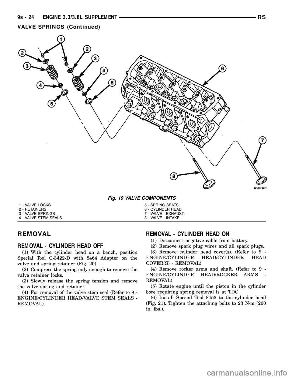
Fig. 19 VALVE COMPONENTS
1 - VALVE LOCKS 5 - SPRING SEATS
2 - RETAINERS 6 - CYLINDER HEAD
3 - VALVE SPRINGS 7 - VALVE - EXHAUST
4 - VALVE STEM SEALS 8 - VALVE - INTAKE
9s - 24 ENGINE 3.3/3.8L SUPPLEMENTRS
VALVE SPRINGS (Continued)
Page 1481 of 2585

INSTALLATION
INSTALLATION - CYLINDER HEAD OFF
(1) If removed, install a new valve stem seal (Refer
to 9 - ENGINE/CYLINDER HEAD/VALVE STEM
SEALS - INSTALLATION).
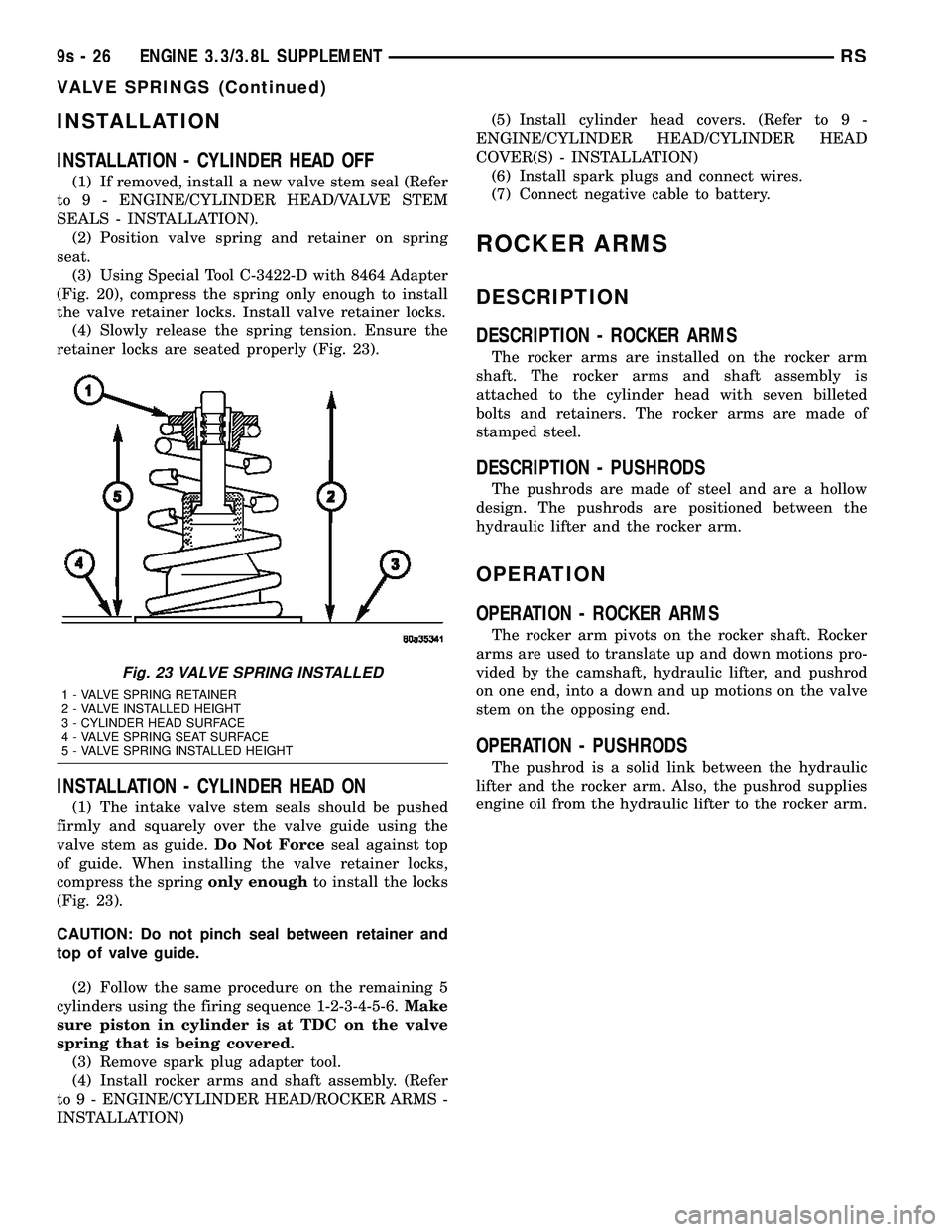
(2) Position valve spring and retainer on spring
seat.
(3) Using Special Tool C-3422-D with 8464 Adapter
(Fig. 20), compress the spring only enough to install
the valve retainer locks. Install valve retainer locks.
(4) Slowly release the spring tension. Ensure the
retainer locks are seated properly (Fig. 23).
INSTALLATION - CYLINDER HEAD ON
(1) The intake valve stem seals should be pushed
firmly and squarely over the valve guide using the
valve stem as guide.Do Not Forceseal against top
of guide. When installing the valve retainer locks,
compress the springonly enoughto install the locks
(Fig. 23).
CAUTION: Do not pinch seal between retainer and
top of valve guide.
(2) Follow the same procedure on the remaining 5
cylinders using the firing sequence 1-2-3-4-5-6.Make
sure piston in cylinder is at TDC on the valve
spring that is being covered.
(3) Remove spark plug adapter tool.
(4) Install rocker arms and shaft assembly. (Refer
to 9 - ENGINE/CYLINDER HEAD/ROCKER ARMS -
INSTALLATION)(5) Install cylinder head covers. (Refer to 9 -
ENGINE/CYLINDER HEAD/CYLINDER HEAD
COVER(S) - INSTALLATION)
(6) Install spark plugs and connect wires.
(7) Connect negative cable to battery.
ROCKER ARMS
DESCRIPTION
DESCRIPTION - ROCKER ARMS
The rocker arms are installed on the rocker arm
shaft. The rocker arms and shaft assembly is
attached to the cylinder head with seven billeted
bolts and retainers. The rocker arms are made of
stamped steel.
DESCRIPTION - PUSHRODS
The pushrods are made of steel and are a hollow
design. The pushrods are positioned between the
hydraulic lifter and the rocker arm.
OPERATION
OPERATION - ROCKER ARMS
The rocker arm pivots on the rocker shaft. Rocker
arms are used to translate up and down motions pro-
vided by the camshaft, hydraulic lifter, and pushrod
on one end, into a down and up motions on the valve
stem on the opposing end.
OPERATION - PUSHRODS
The pushrod is a solid link between the hydraulic
lifter and the rocker arm. Also, the pushrod supplies
engine oil from the hydraulic lifter to the rocker arm.
Fig. 23 VALVE SPRING INSTALLED
1 - VALVE SPRING RETAINER
2 - VALVE INSTALLED HEIGHT
3 - CYLINDER HEAD SURFACE
4 - VALVE SPRING SEAT SURFACE
5 - VALVE SPRING INSTALLED HEIGHT
9s - 26 ENGINE 3.3/3.8L SUPPLEMENTRS
VALVE SPRINGS (Continued)
Page 1490 of 2585

The combustion reaction caused by the catalyst
releases additional heat in the exhaust system, caus-
ing temperature increases in the area of the reactor
under severe operating conditions. Such conditions
can exist when the engine misfires or otherwise does
not operate at peak efficiency.Do notremove spark
plug wires from plugs or by any other means short
out cylinders, if exhaust system is equipped with a
catalytic converter. Failure of the catalytic converter
can occur due to temperature increases caused by
unburned fuel passing through the converter. This
deterioration of the catalyst core can result in exces-
sively high emission levels, noise complaints, and
exhaust restrictions.
Unleaded gasoline must be used to avoid ruining
the catalyst core. Do not allow engine to operate
above 1200 RPM in neutral for extended periods over
5 minutes. This condition may result in excessive
exhaust system/floor pan temperatures because of no
air movement under the vehicle.
The flex joint allows flexing as the engine moves,
preventing breakage that could occur from the back-
and-forth motion of a transverse mounted engine.
CAUTION: Due to exterior physical similarities of
some catalytic converters with pipe assemblies,
extreme care should be taken with replacement
parts. There are internal converter differences
required in some parts of the country (particularly
vehicles built for States with strict emission
requirements) and between model years.
REMOVAL
(1) Loosen clamp and disconnect the muffler/reso-
nator assembly from catalytic converter pipe.
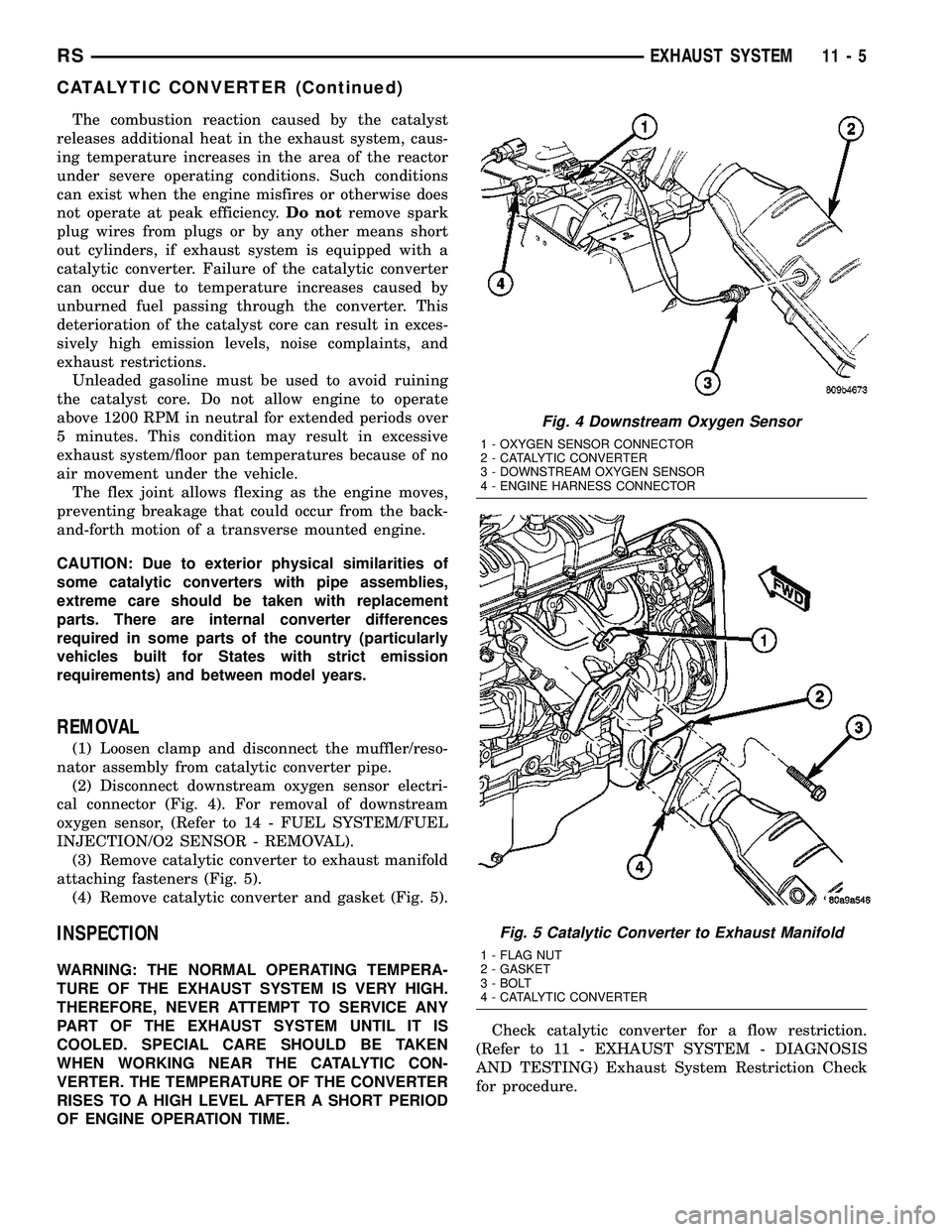
(2) Disconnect downstream oxygen sensor electri-
cal connector (Fig. 4). For removal of downstream
oxygen sensor, (Refer to 14 - FUEL SYSTEM/FUEL
INJECTION/O2 SENSOR - REMOVAL).
(3) Remove catalytic converter to exhaust manifold
attaching fasteners (Fig. 5).
(4) Remove catalytic converter and gasket (Fig. 5).
INSPECTION
WARNING: THE NORMAL OPERATING TEMPERA-
TURE OF THE EXHAUST SYSTEM IS VERY HIGH.
THEREFORE, NEVER ATTEMPT TO SERVICE ANY
PART OF THE EXHAUST SYSTEM UNTIL IT IS
COOLED. SPECIAL CARE SHOULD BE TAKEN
WHEN WORKING NEAR THE CATALYTIC CON-
VERTER. THE TEMPERATURE OF THE CONVERTER
RISES TO A HIGH LEVEL AFTER A SHORT PERIOD
OF ENGINE OPERATION TIME.Check catalytic converter for a flow restriction.
(Refer to 11 - EXHAUST SYSTEM - DIAGNOSIS
AND TESTING) Exhaust System Restriction Check
for procedure.
Fig. 4 Downstream Oxygen Sensor
1 - OXYGEN SENSOR CONNECTOR
2 - CATALYTIC CONVERTER
3 - DOWNSTREAM OXYGEN SENSOR
4 - ENGINE HARNESS CONNECTOR
Fig. 5 Catalytic Converter to Exhaust Manifold
1 - FLAG NUT
2 - GASKET
3 - BOLT
4 - CATALYTIC CONVERTER
RSEXHAUST SYSTEM11-5
CATALYTIC CONVERTER (Continued)
Page 2520 of 2585

period the switch ratio reaches a predetermined
value, a counter is incremented by one. The monitor
is enabled to run another test during that trip. When
the test fails 6 times, the counter increments to 3, a
malfunction is entered, and a Freeze Frame is stored,
the code is matured and the MIL is illuminated. If
the first test passes, no further testing is conducted
during that trip.
The MIL is extinguished after three consecutive
good trips. The good trip criteria for the catalyst
monitor is more stringent than the failure criteria. In
order to pass the test and increment one good trip,
the downstream sensor switch rate must be less than
45% of the upstream rate. The failure percentages
are 59% respectively.
Enabling ConditionsÐThe following conditions
must typically be met before the PCM runs the cat-
alyst monitor. Specific times for each parameter may
be different from engine to engine.
²Accumulated drive time
²Enable time
²Ambient air temperature
²Barometric pressure
²Catalyst warm-up counter
²Engine coolant temperature
²Vehicle speed
²MAP
²RPM
²Engine in closed loop
²Fuel level
Pending ConditionsÐ
²Misfire DTC
²Front Oxygen Sensor Response
²Front Oxygen Sensor Heater Monitor
²Front Oxygen Sensor Electrical
²Rear Oxygen Sensor Rationality (middle check)
²Rear Oxygen Sensor Heater Monitor
²Rear Oxygen Sensor Electrical
²Fuel System Monitor
²All TPS faults
²All MAP faults
²All ECT sensor faults
²Purge flow solenoid functionality
²Purge flow solenoid electrical
²All PCM self test faults
²All CMP and CKP sensor faults
²All injector and ignition electrical faults
²Idle Air Control (IAC) motor functionality
²Vehicle Speed Sensor
²Brake switch (auto trans only)
²Intake air temperature
ConflictÐThe catalyst monitor does not run if any
of the following are conditions are present:
²EGR Monitor in progress (if equipped)
²Fuel system rich intrusive test in progress
²EVAP Monitor in progress²Time since start is less than 60 seconds
²Low fuel level-less than 15 %
²Low ambient air temperature
²Ethanol content learn is taking place and the
ethanol used once flag is set
SuspendÐThe Task Manager does not mature a
catalyst fault if any of the following are present:
²Oxygen Sensor Monitor, Priority 1
²Oxygen Sensor Heater, Priority 1
²EGR Monitor, Priority 1 (if equipped)
²EVAP Monitor, Priority 1
²Fuel System Monitor, Priority 2
²Misfire Monitor, Priority 2
OPERATION - NON-MONITORED CIRCUITS
The PCM does not monitor all circuits, systems
and conditions that could have malfunctions causing
driveability problems. However, problems with these
systems may cause the PCM to store diagnostic trou-
ble codes for other systems or components. For exam-
ple, a fuel pressure problem will not register a fault
directly, but could cause a rich/lean condition or mis-
fire. This could cause the PCM to store an oxygen
sensor or misfire diagnostic trouble code.
The major non-monitored circuits are listed below
along with examples of failures modes that do not
directly cause the PCM to set a DTC, but for a sys-
tem that is monitored.
FUEL PRESSURE
The fuel pressure regulator controls fuel system
pressure. The PCM cannot detect a clogged fuel
pump inlet filter, clogged in-line fuel filter, or a
pinched fuel supply or return line. However, these
could result in a rich or lean condition causing the
PCM to store an oxygen sensor, fuel system, or mis-
fire diagnostic trouble code.
SECONDARY IGNITION CIRCUIT
The PCM cannot detect an inoperative ignition coil,
fouled or worn spark plugs, ignition cross firing, or
open spark plug cables. The misfire will however,
increase the oxygen content in the exhaust, deceiving
the PCM in to thinking the fuel system is too lean.
Also see misfire detection.
CYLINDER COMPRESSION
The PCM cannot detect uneven, low, or high engine
cylinder compression. Low compression lowers O2
content in the exhaust. Leading to fuel system, oxy-
gen sensor, or misfire detection fault.
EXHAUST SYSTEM
The PCM cannot detect a plugged, restricted or
leaking exhaust system. It may set a EGR (if
equipped) or Fuel system or O2S fault.
RSEMISSIONS CONTROL25-5
EMISSIONS CONTROL (Continued)
Page 2568 of 2585

PINS (DISC/DRUM BRAKES) -
INSTALLATION, DISC BRAKE CALIPER
GUIDE..............................5-31
PINS (DISC/DRUM BRAKES) - REMOVAL,
DISC BRAKE CALIPER GUIDE............5-31
PINS (TRW BRAKES) - INSTALLATION,
DISC BRAKE CALIPER GUIDE...........5s-30
PINS (TRW BRAKES) - REMOVAL, DISC
BRAKE CALIPER GUIDE................5s-30
PIPE - 3.3/3.8L - INSTALLATION,
CROSS-OVER........................11-6
PIPE - 3.3/3.8L - REMOVAL, CROSS-
OVER...............................11-6
PIPE - INSTALLATION, AIR INTAKE......24-114
PIPE - REMOVAL, AIR INTAKE.........24-113
PISTON & CONNECTING ROD -
DESCRIPTION...................9-116,9-42
PISTON & CONNECTING ROD -
INSTALLATION........................9-44
PISTON & CONNECTING ROD -
REMOVAL...........................9-43
PISTON AND SEAL - ASSEMBLY,
CALIPER..............5-26,5-29,5s-25,5s-28
PISTON AND SEAL - DISASSEMBLY,
CALIPER..............5-24,5-28,5s-23,5s-27
PISTON RING, FITTING.................9-45
PISTON RING FITTING - STANDARD
PROCEDURE........................9-121
PISTON RINGS - INSTALLATION.........9-121
PISTON RINGS - REMOVAL............9-121
PISTON TO CYLINDER BORE FITTING -
STANDARD PROCEDURE................9-42
PISTONS - STANDARD PROCEDURE,
FITTING............................9-117
PLANETARY GEARTRAIN -
DESCRIPTION...............21-232,21s-132
PLANETARY GEARTRAIN - OPERATION . . 21-232,
21s-132
PLASTIC BODY PANEL REPAIR -
STANDARD PROCEDURE................23-3
PLASTIC GROCERY BAG RETAINER -
INSTALLATION......................23-105
PLASTIC GROCERY BAG RETAINER -
REMOVAL.........................23-104
PLASTIGAGE - STANDARD PROCEDURE,
MEASURING BEARING CLEARANCE
USING..........................9-12,9-84
PLATE - 2.5L TD - INSTALLATION,
CLUTCH DISC AND PRESSURE...........6-12
PLATE - 2.5L TD - REMOVAL, CLUTCH
DISC AND PRESSURE..................6-11
PLATE - DESCRIPTION, BODY CODE....Intro.-1
PLATE - DESCRIPTION, MANUFACTURER . Intro.-11
PLATE - DRUM BRAKE - INSTALLATION,
SUPPORT.......................5-56,5s-58
PLATE - DRUM BRAKE - REMOVAL,
SUPPORT.......................5-56,5s-58
PLATE - INSTALLATION, DOOR SILL
TRIM..............................23-77
PLATE - INSTALLATION, FLEX...........9-131
PLATE - INSTALLATION, LIFTGATE SILL . . . 23-79
PLATE - INSTALLATION, SLIDING DOOR
SILL...............................23-82
PLATE - INSTALLATION, STEERING
COLUMN COVER BACKING.............23-70
PLATE - REMOVAL, DOOR SILL TRIM....23-77
PLATE - REMOVAL, FLEX..............9-131
PLATE - REMOVAL, LIFTGATE SILL.......23-79
PLATE - REMOVAL, SLIDING DOOR SILL . . 23-82
PLATE - REMOVAL, STEERING COLUMN
COVER BACKING.....................23-70
PLATE BATTERY CHARGING -
STANDARD PROCEDURE, SPIRAL........8F-10
PLATE MISALIGNMENT - DIAGNOSIS
AND TESTING, DRIVE...................6-6
PLATES - ADHESIVE ATTACHED -
INSTALLATION, EXTERIOR NAME........23-51
PLATES - ADHESIVE ATTACHED -
REMOVAL, EXTERIOR NAME............23-51
PLATES - TAPE ATTACHED -
INSTALLATION, EXTERIOR NAME
........23-51
PLATES - TAPE ATTACHED - REMOVAL,
EXTERIOR NAME
.....................23-51
PLATINUM PLUGS - DESCRIPTION
........8I-9
PLAY - ADJUSTMENT, DIFFERENTIAL
SIDE GEAR END
.....................21-70
PLAY - STANDARD PROCEDURE,
CRANKSHAFT END
................9-36,9s-6PLAY - STANDARD PROCEDURE,
MEASURING CAMSHAFT END............9-29
PLAY - STANDARD PROCEDURE,
MEASURING CRANKSHAFT END.........9-125
PLAYER - DESCRIPTION, DVD...........8A-8
PLAYER - INSTALLATION, DVD...........8A-8
PLAYER - OPERATION, DVD.............8A-8
PLAYER - REMOVAL, DVD..............8A-8
PLUG CABLE - DESCRIPTION, SPARK.....8I-10
PLUG CABLE RESISTANCE,
SPECIFICATIONS - SPARK...............8I-2
PLUG, SPECIFICATIONS - SPARK.........8I-2
PLUGS - DESCRIPTION, PLATINUM........8I-9
PLUGS - STANDARD PROCEDURE,
ENGINE CORE AND OIL GALLERY....9-10,9-86
POINTS - DESCRIPTION, LUBRICATION.....0-7
POLISHING - DESCRIPTION, FINESSE
SANDING/BUFFING...................23-85
PORT REPAIR - STANDARD
PROCEDURE, INTAKE MANIFOLD
VACUUM...........................9-145
PORT VALVE CORE - DESCRIPTION,
SERVICE...........................24-94
PORT VALVE CORE - INSTALLATION,
SERVICE...........................24-94
PORT VALVE CORE - REMOVAL,
SERVICE...........................24-94
POSITION SENSOR - DESCRIPTION,
CAMSHAFT...........................8I-4
POSITION SENSOR - DESCRIPTION,
CRANKSHAFT.......................14-25
POSITION SENSOR - DESCRIPTION,
THROTTLE..........................14-36
POSITION SENSOR - OPERATION,
CAMSHAFT...........................8I-4
POSITION SENSOR - OPERATION,
CRANKSHAFT.......................14-25
POSITION SENSOR - OPERATION,
THROTTLE..........................14-36
POSITION SENSOR - REMOVAL,
CRANKSHAFT.......................14-25
POTENTIAL - STANDARD PROCEDURE,
TESTING OF VOLTAGE..............8W-01-9
POWER - INSTALLATION, WINDOW
REGULATOR........................23-22
POWER - REMOVAL, WINDOW
REGULATOR........................23-22
POWER ADJUSTER - INSTALLATION,
FRONT SEAT TRACK..................23-95
POWER ADJUSTER - REMOVAL, FRONT
SEAT TRACK........................23-95
POWER BRAKE BOOSTER -
DESCRIPTION...................5-40,5s-43
POWER BRAKE BOOSTER - DIAGNOSIS
AND TESTING...................5-41,5s-44
POWER BRAKE BOOSTER - OPERATION . . . 5-41,
5s-44
POWER DISTRIBUTION SYSTEM -
DESCRIPTION.....................8W-97-1
POWER DISTRIBUTION SYSTEM -
OPERATION.......................8W-97-1
POWER DISTRIBUTION SYSTEMS,
SPECIAL TOOLS...................8W-97-1
POWER DOOR LEARN CYCLE -
STANDARD PROCEDURE..............8N-28
POWER FOLDAWAY MIRROR SWITCH -
EXPORT - DESCRIPTION...............8N-48
POWER FOLDAWAY MIRROR SWITCH -
EXPORT - INSTALLATION..............8N-49
POWER FOLDAWAY MIRROR SWITCH -
EXPORT - OPERATION................8N-48
POWER FOLDAWAY MIRROR SWITCH -
EXPORT - REMOVAL..................8N-48
POWER LIFTGATE CONTROL MODULE -
DESCRIPTION.......................8E-10
POWER LIFTGATE CONTROL MODULE -
INSTALLATION.......................8E-11
POWER LIFTGATE CONTROL MODULE -
OPERATION.........................8E-11
POWER LIFTGATE CONTROL MODULE -
REMOVAL
..........................8E-11
POWER LIFTGATE LEARN CYCLE -
STANDARD PROCEDURE
...............8N-9
POWER LIFTGATE SYSTEM -
DESCRIPTION
........................8N-2
POWER LIFTGATE SYSTEM - DIAGNOSIS
AND TESTING
........................8N-4
POWER LIFTGATE SYSTEM - OPERATION
. . 8N-3POWER LOCKS - DESCRIPTION.....8N-1,8N-38
POWER LOCKS - OPERATION......8N-2,8N-39
POWER MIRRORS - DESCRIPTION......8N-45
POWER MIRRORS - DIAGNOSIS AND
TESTING...........................8N-46
POWER MIRRORS - OPERATION........8N-45
POWER MODULE - BLOWER MOTOR -
DESCRIPTION.......................24-31
POWER MODULE - BLOWER MOTOR -
INSTALLATION.......................24-32
POWER MODULE - BLOWER MOTOR -
OPERATION.........................24-31
POWER MODULE - BLOWER MOTOR -
REMOVAL..........................24-31
POWER MODULE - DESCRIPTION,
INTEGRATED......................8W-97-2
POWER MODULE - INSTALLATION,
INTEGRATED......................8W-97-3
POWER MODULE - OPERATION,
INTEGRATED......................8W-97-2
POWER MODULE - REAR BLOWER
MOTOR - DESCRIPTION...............24-41
POWER MODULE - REAR BLOWER
MOTOR - INSTALLATION...............24-42
POWER MODULE - REAR BLOWER
MOTOR - OPERATION.................24-41
POWER MODULE - REAR BLOWER
MOTOR - REMOVAL..................24-41
POWER MODULE - REMOVAL,
INTEGRATED......................8W-97-2
POWER OUTLET - DESCRIPTION......8W-97-4
POWER OUTLET - DIAGNOSIS &
TESTING.........................8W-97-4
POWER OUTLET - OPERATION........8W-97-4
POWER SEAT SYSTEM - DIAGNOSIS
AND TESTING...................8N-52,8N-9
POWER SEAT SYSTEM - OPERATION....8N-52,
8N-9
POWER SEAT TRACK - DESCRIPTION,
DRIVER.......................8N-15,8N-58
POWER SEAT TRACK - DESCRIPTION,
PASSENGER...................8N-16,8N-59
POWER SEAT TRACK - DIAGNOSIS AND
TESTING......................8N-17,8N-60
POWER SEAT TRACK - DIAGNOSIS AND
TESTING, DRIVER...............8N-15,8N-58
POWER SEAT TRACK - INSTALLATION,
DRIVER.......................8N-16,8N-59
POWER SEAT TRACK - INSTALLATION,
PASSENGER...................8N-18,8N-61
POWER SEAT TRACK - OPERATION,
DRIVER.......................8N-15,8N-58
POWER SEAT TRACK - OPERATION,
PASSENGER...................8N-17,8N-60
POWER SEAT TRACK - REMOVAL,
DRIVER.......................8N-16,8N-59
POWER SEAT TRACK - REMOVAL,
PASSENGER...................8N-18,8N-61
POWER SLIDING DOOR SYSTEM -
DESCRIPTION.......................8N-19
POWER SLIDING DOOR SYSTEM -
DIAGNOSIS AND TESTING.............8N-22
POWER SLIDING DOOR SYSTEM -
OPERATION.........................8N-21
POWER STEERING BELT TENSION -
STANDARD PROCEDURE, CHECKING.......7-8
POWER STEERING FASTENER TORQUE,
SPECIFICATIONS......................19-9
POWER STEERING FLUID LEVEL
CHECKING - STANDARD PROCEDURE....19-44
POWER STEERING GEAR, SPECIAL
TOOLS.............................19-34
POWER STEERING PUMP INITIAL
OPERATION - STANDARD PROCEDURE . . . 19-37
POWER STEERING PUMP, SPECIAL
TOOLS.............................19-43
POWER STEERING, SPECIAL TOOLS......19-9
POWER STEERING SYSTEM -
DESCRIPTION........................19-1
POWER STEERING SYSTEM -
OPERATION
..........................19-1
POWER STEERING SYSTEM FLOW AND
PRESSURE TEST - DIAGNOSIS AND
TESTING
............................19-1
POWER TRANSFER UNIT - DESCRIPTION
. . 21-1
POWER TRANSFER UNIT - OPERATION
....21-3
POWER TRANSFER UNIT FLUID -
DESCRIPTION, AWD
....................0-6
RSINDEX25
Description Group-Page Description Group-Page Description Group-Page