Power system CHRYSLER VOYAGER 2004 Workshop Manual
[x] Cancel search | Manufacturer: CHRYSLER, Model Year: 2004, Model line: VOYAGER, Model: CHRYSLER VOYAGER 2004Pages: 2585, PDF Size: 62.54 MB
Page 411 of 2585
Refer to the appropriate Powertrain Diagnostic Man-
ual and the DRBIIItscan tool.
(1) Install PCM module to the mounting bracket.
(2) Install electrical connectors and lock.
(3) Install the splash shield.
(4) Lower vehicle.
(5) Connect the negative battery cable.
(6) Using DRBIIItscan tool, program mileage and
vehicle identification number (VIN) into PCM. Refer
to the DRBIIItscan tool and the appropriate Power-
train Diagnostic Manual.
SENTRY KEY IMMOBILIZER
MODULE
DESCRIPTION
The Sentry Key Immobilizer Module (SKIM) con-
tains a Radio Frequency (RF) transceiver and a
microprocessor. The SKIM retains in memory the ID
numbers of any Sentry Key that is programmed to it.
The maximum number of keys that may be pro-
grammed to each module is eight (8). The SKIM also
communicates over the Programmable Communica-
tion Interface (PCI) data bus with the Powertrain
Control Module (PCM), the Body Control Module
(BCM), the Mechanical Instrument Cluster (MIC),
and the DRB IIItscan tool. The SKIM transmits and
receives RF signals through a tuned antenna
enclosed within a molded plastic ring formation that
is integral to the SKIM housing. When the SKIM is
properly installed on the steering column, the
antenna ring fits snugly around the circumference of
the ignition lock cylinder housing. If this ring is not
mounted properly, communication problems may
arise in the form of transponder-related faults.
For added system security, each SKIM is pro-
grammed with a unique9Secret Key9code. This code
is stored in memory and is sent over the PCI bus to
the PCM and to each key that is programmed to
work with the vehicle. The9Secret Key9code is there-
fore a common element found in all components of
the Sentry Key Immobilizer System (SKIS). In the
event that a SKIM replacement is required, the
9Secret Key9code can be restored from the PCM by
following the SKIM replacement procedure found in
the DRB IIItscan tool. Proper completion of this
task will allow the existing ignition keys to be repro-
grammed. Therefore, new keys will NOT be needed.
In the event that the original9Secret Key9code can
not be recovered, new ignition keys will be required.
The DRB IIItscan tool will alert the technician if
key replacement is necessary. Another security code,
called a PIN, is used to gain secured access to the
SKIM for service. The SKIM also stores in its mem-
ory the Vehicle Identification Number (VIN), which itlearns through a bus message from the assembly
plant tester. The SKIS scrambles the information
that is communicated between its components in
order to reduce the possibility of unauthorized SKIM
access and/or disabling.
OPERATION
When the ignition switch is moved to the RUN
position, the Sentry Key Immobilizer Module (SKIM)
transmits an Radio Frequency (RF) signal to the
transponder in the ignition key. The SKIM then
waits for a response RF signal from the transponder
in the key. If the response received identifies the key
as valid, the SKIM sends a9valid key9message to
the Powertrain Control Module (PCM) over the Pro-
grammable Communication Interface (PCI) data bus.
If the response received identifies the key as invalid
or no response is received from the transponder in
the ignition key, the SKIM sends an9invalid key9
message to the PCM. The PCM will enable or disable
engine operation based upon the status of the SKIM
messages. It is important to note that the default
condition in the PCM is9invalid key.9Therefore, if no
response is received by the PCM, the engine will be
immobilized after two (2) seconds of running.
The SKIM also sends indicator light status mes-
sages to the Mechanical Instrument Cluster (MIC) to
operate the light. This is the method used to turn the
light ON solid or to flash it after the indicator light
test is complete to signify a fault in the SKIS. If the
light comes ON and stays ON solid after the indica-
tor light test, this signifies that the SKIM has
detected a system malfunction and/or that the SKIS
has become inoperative. If the SKIM detects an
invalid keyORa key-related fault exists, the indica-
tor light will flash following the indicator light test.
The SKIM may also request an audible chime if the
customer key programming feature is available and
the procedure is being utilized (Refer to 8 - ELEC-
TRICAL/VEHICLE THEFT SECURITY/TRANSPON-
DER KEY - STANDARD PROCEDURE).
REMOVAL
(1) Disconnect and isolate the battery negative
cable.
(2) Remove Lower Instrument Panel Cover. Refer
to Body, Instrument Panel, Lower Instrument Panel
Cover, Removal.
(3) Remove the steering column upper and lower
shrouds. Refer to Steering, Column, Column Shroud,
Removal.
(4) Disengage the steering column wire harness
from the Sentry Key Immobilizer Module (SKIM).
(5) Remove the one screws securing the SKIM to
the steering column.
8E - 18 ELECTRONIC CONTROL MODULESRS
POWERTRAIN CONTROL MODULE (Continued)
Page 412 of 2585

(6) Rotate the SKIM upwards and then to the side
away from the steering column to slide the SKIM
antenna ring from around the ignition switch lock
cylinder housing.
(7) Remove the SKIM from the vehicle.
INSTALLATION
(1) Slip the SKIM antenna ring around the igni-
tion switch lock cylinder housing. Rotate the SKIM
downwards and then towards the steering column.
(2) Install the one screws securing the SKIM to
the steering column.
(3) Engage the steering column wire harness from
the Sentry Key Immobilizer Module (SKIM).
(4) Install the steering column upper and lower
shrouds. Refer to Steering, Column, Column Shroud,
Installation.
(5) Install the Lower Instrument Panel Cover.
Refer to Body, Instrument Panel, Lower Instrument
Panel Cover, Installation.
(6) Connect the battery negative cable.
SLIDING DOOR CONTROL
MODULE
DESCRIPTION
Vehicles equipped with a power sliding door utilize
a sliding door control module. The sliding door con-
trol module is located behind the sliding door trim
panel in the center of the door, just above the sliding
door motor (Fig. 15). This module controls the opera-
tion of the door through the Programmable Commu-
nication Interface (PCI) J1850 data bus circuit and
the Body Control Module. The sliding door control
module contains software technology which enables it
to detect resistance to door travel and to reverse door
travel in order to avoid damage to the door or to
avoid possible personal injury if the obstruction is a
person. This feature functions in both the opening
and closing cycles. If the power sliding door system
develops any problems the control module will store
and recall Diagnostic Trouble Codes (DTC). The use
of a diagnostic scan tool, such as the DRB IIItis
required to read and troubleshoot these trouble
codes. The sliding door control module can be
reflashed if necessary. Refer to the latest Technical
Service Bulletin (TSB) Information for any updates.
The power door control module is a replaceable
component and cannot be repaired, if found to be
faulty it must be replaced. Consult your MoparŸ
parts catalog for a specific part number.
OPERATION
The power sliding door control module serves as
the main computer for the power sliding side doorsystem. All power door functions are processed
through the power door control module and/or the
vehicles body control module (BCM). At the start of a
power open command, a signal is sent to the BCM
and then to the power door control module via the
J1850 data bus circuit. This signal, generated by any
of the power door command switches, tells the power
door control module to activate a power latch release,
engage the clutch assembly and drive the door into
the full open position. If an obstacle is felt during
this power open cycle, the module will reverse direc-
tion and close the door. This process is also enabled
during a power close cycle. This process will repeat
three times, and if a fourth obstacle is detected, the
door will go into full manual mode. Once the full
open position is obtained, a hold open latch assembly
mounted full open switch tells the control module
that the door has reached the full open position. If
the power sliding door system develops any problems
the control module will store and recall Diagnostic
Trouble Codes (DTC). The use of a diagnostic scan
tool, such as the DRB IIItis required to read and
troubleshoot these trouble codes.
REMOVAL
(1) Disconnect and isolate the negative battery
cable.
Fig. 15 Power Side Door Components
1 - SLIDING DOOR CONTROL MODULE
2 - MODULE RETAINING SCREW
3 - MODULE ELECTRICAL CONNECTORS
4 - DOOR MOTOR ASSEMBLY
5 - FLEX DRIVE ASSEMBLY
6 - DOOR MOTOR RETAINING FASTENERS
7 - DOOR MOTOR ELECTRICAL CONNECTOR
RSELECTRONIC CONTROL MODULES8E-19
SENTRY KEY IMMOBILIZER MODULE (Continued)
Page 413 of 2585

(2) Remove the appropriate door trim panel from
the vehicle. Refer to Body for the procedure.
(3) Remove the weather shield. Refer to Body for
the procedure.
(4) Disconnect the power door control module elec-
trical connectors. Slide the red locking tab out (away
from module) and depress connector retaining tab,
while pulling straight apart.
(5) Remove the control module retaining screw
(Fig. 15).
(6) Remove the module from the vehicle.
INSTALLATION
(1) Position the control module and install the
retaining screw.
(2) Connect the control module electrical connec-
tors. Slide the locking tab into the locked position.
(3) Install the appropriate door trim panel on the
vehicle. Refer to Body for the procedure.
(4) Install the weather shield. Refer to Body for
the procedure.
(5) Connect the negative battery cable.
(6) Using an appropriate scan tool, check and
erase any power door control module diagnostic trou-
ble codes.
(7) Verify power door system operation. Cycle the
power door through one complete open and close
cycle.
TRANSMISSION CONTROL
MODULE
DESCRIPTION
On models equipped with the 2.4L Engine option,
the Transmission Control Module (TCM) is located
behind the left fender and is fastened with three
screws to three clips in the left frame rail forward of
the suspension (Fig. 16). Models equipped with the
3.3/3.8L Engine option utilize a Powertrain Control
Module (PCM) which incorporates TCM functionality.
OPERATION
The TCM is the controlling unit for all electronic
operations of the transaxle. The TCM receives infor-
mation regarding vehicle operation from both direct
and indirect inputs, and selects the operational mode
of the transaxle. Direct inputs are hardwired to, and
used specifically by the TCM. Indirect inputs origi-
nate from other components/modules, and are shared
with the TCM via the J1850 communication bus.
Some examples ofdirect inputsto the TCM are:
²Battery (B+) voltage
²Ignition ªONº voltage
²Transmission Control Relay (Switched B+)
²Throttle Position Sensor²Crankshaft Position Sensor (CKP)
²Transmission Range Sensor (TRS)
²Pressure Switches (L/R, 2/4, OD)
²Transmission Temperature Sensor (Integral to
TRS)
²Input Shaft Speed Sensor
²Output Shaft Speed Sensor
Some examples ofindirect inputsto the TCM
are:
²Engine/Body Identification
²Manifold Pressure
²Target Idle
²Torque Reduction Confirmation
²Speed Control ON/OFF Switch
²Engine Coolant Temperature
²Ambient/Battery Temperature
²Brake Switch Status
²DRB Communication
Based on the information received from these var-
ious inputs, the TCM determines the appropriate
shift schedule and shift points, depending on the
present operating conditions and driver demand.
This is possible through the control of various direct
and indirect outputs.
Some examples of TCMdirect outputsare:
²Transmission Control Relay
²Solenoids (LR/CC, 2/4, OD and UD)
²Vehicle Speed (to PCM)
²Torque Reduction Request (to PCM)
An example of a TCMindirect outputis:
²Transmission Temperature (to PCM)
Fig. 16 Transmission Control Module (TCM)
Location
1 - TRANSMISSION CONTROL MODULE (TCM)
8E - 20 ELECTRONIC CONTROL MODULESRS
SLIDING DOOR CONTROL MODULE (Continued)
Page 418 of 2585
BODY CONTROL MODULE
TABLE OF CONTENTS
page page
BODY CONTROL MODULE DESCRIPTION ..........................1
OPERATION ............................1 REMOVAL
.............................3
INSTALLATION ..........................3
BODY CONTROL MODULE
DESCRIPTION
The Body Control Module (BCM) is located in the
passenger compartment, attached to the bulkhead
underneath the left side of the instrument panel. The BCM utilizes integrated circuitry and informa-
tion carried on the Programmable Communications
Interface (PCI) data bus network along with many
hard wired inputs to monitor many sensor and
switch inputs throughout the vehicle. In response to
those inputs, the internal circuitry and programming
of the BCM allow it to control and integrate many
electronic functions and features of the vehicle
through both hard wired outputs and the transmis-
sion of electronic message outputs to other electronic
modules in the vehicle over the PCI data bus.
OPERATION
The Body Control Module (BCM) supplies vehicle
occupants with visual and audible information and
controls various vehicle functions. To provide and
receive information, the BCM is interfaced to the
vehicle's serial bus communications network, referred
to as the Programmable Communications Interface
(PCI) bus. This network consists of the;
² Powertrain Control Module (PCM)
² Transmission Control Module (TCM)
² Mechanical Instrument Cluster (MIC)
² Occupant Restraint Controller (ORC)
² Compass/Mini-Trip Computer (CMTC)
² Electronic Vehicle Information Center (EVIC)
² Controller Antilock Brake (CAB)
² HVAC Control Module
² Sliding Door Control Modules (driver and pas-
senger side doors) ² Power Liftgate Module (PLG) ²
Audio system equipped with RAZ, RBU, RBK,
and RBB radios. ² Sentry Key Remote Entry Module (SKREEM).
² Side Impact Airbag Control Module (SIACM)
² Memory Seat Module (MSM)
² Sentry Key Immobilizer Module (SKIM)
The BCM is operational when battery power is
supplied to the module. The BCM provides the following features:
² Power Door Locks
² Automatic Door Locks
² Battery Protection - The BCM will automatically
turn off all exterior lamps after 3 minutes, and all
interior lamps after 15 minutes after the ignition is
turned off, if they are not turned off by the driver. ² Chime Control
² Compass/Mini-Trip support.
² Interior Lighting (Courtesy/Reading Lamps)
² BCM Diagnostic Reporting
² Electronic Liftgate Release (with Power Door
Locks) ² Exterior Lighting
² Headlamp Time Delay (with/without Automatic
Headlamps) ² Illuminated Entry
² Fade to Off Interior Lamps - This feature dims
the interior lighting (courtesy lamps) gradually if the
BCM does not receive any new inputs that would
cause the interior lamps to remain on. ² Pulse Width Modulated Instrument Panel Dim-
ming ² Door Lock Inhibit - This feature disables the
door lock functions if the key is in the ignition and
either front door is ajar. Pressing the Remote Keyless
Entry (RKE) lock/unlock button under these condi-
tions result in normal lock/unlock activation. The BCM has the ability to LEARN additional fea-
tures in the vehicle, provided the appropriate switch
input and PCI data bus messages are received. Refer
to the LEARNED FEATURES table.
RS BODY CONTROL MODULE8Es-1
Page 419 of 2585

LEARNED FEATURES
FEATURE LEARNING KEY
REAR WIPER CONTROL ON HVAC CONTROL ON
INSTRUMENT PANEL PCI BUS MESSAGE RECEIVED FROM HVAC
CONTROL
AUTOMATIC HEADLAMPS PCI MESSAGE FROM OVERHEAD OR HEADLAMP SWITCH POSITION (AUTO)
REMOTE KEYLESS ENTRY SKREEM MESSAGE RECEIVED FROM MODULE
FRONT FOG LAMPS HEADLAMP SWITCH POSITION (PARK W/FRONT FOG LAMPS)
POWER SLIDING DOOR PCI IFR RECEIVED FROM MODULE
THE BCM HAS FOUR SWITCH INPUTS FOR THE POWER SLIDING DOOR FEATURE; LOCATED IN THE
OVERHEAD CONSOLE ARE THE LEFT AND RIGHT SIDE SLIDING DOOR SWITCHES TO ACTIVATE EITHER
OR BOTH SLIDING DOORS UNDER THE PROPER CONDITIONS. ALSO ARE B-PILLAR SWITCHES LOCATED
ON THE LEFT AND RIGHT B-PILLAR POSTS.
POWER LIFTGATE PCI IFR RECEIVED FROM MODULE
THE BCM HAS ONE LIFTGATE INPUT LOCATED IN THE OVERHEAD CONSOLE.
POWER LOCKOUT SWITCH INPUT
THE BCM HAS ONE LOCKOUT SWITCH INPUT THAT WHEN ENABLED WILL DISABLE THE B-PILLAR
SLIDING DOOR SWITCHES FROM ACTIVATING EITHER SLIDING DOOR WHEN DEPRESSED.
PCI AUDIO SYSTEM PCI MESSAGE RECEIVED FROM MODULE
REMOTE RADIO CONTROLS REMOTE RADIO SWITCHES PRESENT
VEHICLE THEFT SECURITY SKREEM MESSAGE RECEIVED, VALID KEY RECEIVED, & DIAGNOSTIC PID RECEIVED.
MEMORY SEAT AND MIRRORS MEMORY SEAT SWITCH PRESENT AND OR PCI MESSAGE RECEIVED FROM MEMORY MODULE
ABS W/TRACTION CONTROL PCI MESSAGE RECEIVED FROM CAB
SENTRY KEY IMMOBILIZER SYSTEM PCI MESSAGE RECEIVED FROM SKIM OR VTSS PRESENT
ADJUSTABLE PEDAL MODULE PCI MESSAGE RECEIVED FROM ADJUSTABLE PEDAL MODULE (APM)
8Es - 2 BODY CONTROL MODULERS
BODY CONTROL MODULE (Continued)
Page 420 of 2585
When replacing a BCM there are three modules
available: ² Base
² Midline
² RG - Export
The Midline controller is used on vehicles that
have Power Door Locks. If a vehicle is equipped with
the Vehicle Theft Security System, the Midline con-
troller becomes a Premium when the theft feature is
enabled.
CAUTION: Do not swap Body Control Modules
between vehicles or body controller's off the shelf.
The BCM has internal diagnostic capability that
assists in diagnosing the system error. When an
OPEN or a SHORT circuit exists, the diagnostic tool
can be used to read the BCM faults. The faults are
very descriptive in identifying the appropriate fea-
ture that has faulted. The only two faults that the BCM logs that con-
clude the replacement of a BCM are faults; ² # 01 - Internal BCM failure (replace BCM)
² # 1F - J1850 Internal Hardware Failure (replace
BCM) Otherwise the appropriate diagnostic procedures
for each of the features should be taken when the
BCM logs a fault.REMOVAL
(1) Disconnect and isolate the battery negative
cable. (2) Remove the lower instrument panel silencer.
(3) Remove the knee blocker and reinforcement
(Refer to 23 - BODY/INSTRUMENT PANEL/KNEE
BLOCKER REINFORCEMENT - REMOVAL). (4) Disconnect the five wire connectors from the
bottom of the Body Control Module (BCM). (5) Move bulkhead wiring aside.
(6) Remove the screws holding the BCM to the
bulkhead. (7) Remove the BCM from the mounting bracket.
INSTALLATION
(1) Install the BCM to the mounting bracket.
(2) Install the screws holding the BCM to the
bulkhead. (3) Connect the five wire connectors to the bottom
of the Body Control Module (BCM). (4) Install the knee blocker and reinforcement
(Refer to 23 - BODY/INSTRUMENT PANEL/KNEE
BLOCKER REINFORCEMENT - INSTALLATION). (5) Install the lower instrument panel silencer.
(6) Connect the battery negative cable.
(7) Verify proper operation of BCM and its
functions.
RS BODY CONTROL MODULE8Es-3
BODY CONTROL MODULE (Continued)
Page 423 of 2585
²Battery Holddown- The battery holddown
hardware secures the battery in the battery tray in
the engine compartment.
²Battery Thermowrap- The battery thermow-
rap insulates the battery to protect it from engine
compartment temperature extremes.
²Battery Tray- The battery tray provides a
secure mounting location in the vehicle for the bat-
tery and an anchor point for the battery holddown
hardware.
For battery system maintenance schedules and
jump starting procedure, see the owner's manual in
the vehicle glove box. Optionally, refer to the Lubri-
cation and Maintenance section of this manual for
the recommended battery maintenance schedules and
for the proper battery jump starting procedure. While
battery charging can be considered a maintenance
procedure, the battery charging procedure and
related information are located later in this section of
this service manual. This was done because the bat-
tery must be fully-charged before any battery system
diagnosis or testing procedures can be performed.
OPERATION
The battery system is designed to provide a safe,
efficient, reliable and mobile means of delivering and
storing electrical energy. This electrical energy is
required to operate the engine starting system, as
well as to operate many of the other vehicle acces-
sory systems for limited durations while the engine
and/or the charging system are not operating. The
battery system is also designed to provide a reserve
of electrical energy to supplement the charging sys-
tem for short durations while the engine is running
and the electrical current demands of the vehicle
exceed the output of the charging system. In addition
to delivering, and storing electrical energy for the
vehicle, the battery system serves as a capacitor and
voltage stabilizer for the vehicle electrical system. It
absorbs most abnormal or transient voltages caused
by the switching of any of the electrical components
or circuits in the vehicle.
DIAGNOSIS AND TESTING - BATTERY SYSTEM
The battery, starting, and charging systems in the
vehicle operate with one another and must be tested
as a complete system. In order for the engine to start
and the battery to maintain its charge properly, all of
the components that are used in these systems must
perform within specifications. It is important that
the battery, starting, and charging systems be thor-
oughly tested and inspected any time a battery needs
to be charged or replaced. The cause of abnormal bat-
tery discharge, overcharging or early battery failure
must be diagnosed and corrected before a battery is
replaced and before a vehicle is returned to service.
The service information for these systems has been
separated within this service manual to make it eas-
ier to locate the specific information you are seeking.
However, when attempting to diagnose any of these
systems, it is important that you keep their interde-
pendency in mind.
The diagnostic procedures used for the battery,
starting, and charging systems include the most
basic conventional diagnostic methods, to the more
sophisticated On-Board Diagnostics (OBD) built into
the Powertrain Control Module (PCM). Use of an
induction-type milliampere ammeter, a volt/ohmme-
ter, a battery charger, a carbon pile rheostat (load
tester) and a 12-volt test lamp may be required. All
OBD-sensed systems are monitored by the PCM.
Each monitored circuit is assigned a Diagnostic Trou-
ble Code (DTC). The PCM will store a DTC in elec-
tronic memory for any failure it detects. Refer to
Charging System for the proper charging system on-
board diagnostic test procedures.
MICRO 420 BATTERY TESTER
The Micro 420 automotive battery system tester is
designed to help the dealership technicians diagnose
the cause of a defective battery. Follow the instruc-
tion manual supplied with the tester to properly
diagnose a vehicle. If the instruction manual is not
available refer to the standard procedure in this sec-
tion, which includes the directions for using the
Micro 420 battery tester.
8F - 2 BATTERY SYSTEMRS
BATTERY SYSTEM (Continued)
Page 428 of 2585

SPECIAL TOOLS
BATTERY SYSTEM SPECIAL TOOLS
BATTERY
DESCRIPTION
There are three different batteries available on this
model. Vehicles equipped with a diesel engine utilize
a spiral wound plate designed battery with recombi-
nation technology. This is a maintenance-free battery
that is capable of delivering more power than a con-
ventional battery. This additional power is required
by a diesel engine during cold cranking. Vehicles
equipped with a gasoline engine utilize a conven-
tional battery. Refer to the following information for
detailed differences and descriptions of these batter-
ies.
SPIRAL PLATE BATTERY - DIESEL ENGINE
Spiral plate technology takes the elements of tradi-
tional batteries - lead and sulfuric acid - to the next
level. By tightly winding layers of spiral grids and
acid-permeated vitreous separators into cells, the
manufacturer has developed a battery with more
power and service life than conventional batteries the
same size. The spiral plate battery is completely, per-
manently sealed. Through gas recombination, hydro-
gen and oxygen within the battery are captured
during normal charging and reunited to form the
water within the electrolyte, eliminating the need to
add distilled water. Therefore, these batteries havenon-removable battery vent caps (Fig. 4). Watercan-
notbe added to this battery.
The acid inside a spiral plate battery is bound
within the vitreous separators, ending the threat of
acid leaks. This feature allows the battery to be
installed in any position anywhere in the vehicle.
Spiral plate technology is the process by which the
plates holding the active material in the battery are
wound tightly in coils instead of hanging flat, like
conventional batteries. This design has a lower inter-
nal resistance and also increases the active material
surface area.
WARNING: NEVER EXCEED 14.4 VOLTS WHEN
CHARGING A SPIRAL PLATE BATTERY. PERSONAL
INJURY AND/OR BATTERY DAMAGE MAY RESULT.
Due to the maintanance-free design, distilled water
cannot be added to this battery. Therefore, if more
than 14.4 volts are used during the spiral plate bat-
tery charging process, water vapor can be exhausted
through the pressure-sensitive battery vents and lost
for good. This can permanently damage the spiral
plate battery. Never exceed 14.4 volts when charging
a spiral plate battery. Personal injury and/or battery
damage may result.
CONVENTIONAL BATTERY - GASOLINE ENGINE
Low-maintenance batteriesare used on export
vehicles equipped with a gasoline engine, these bat-
teries have removable battery cell caps (Fig. 5).
Watercanbe added to this battery. Under normal
MICRO 420 BATTERY TESTER
Fig. 4 MAINTENANCE-FREE DIESEL ENGINE
BATTERY
RSBATTERY SYSTEM8F-7
BATTERY SYSTEM (Continued)
Page 434 of 2585
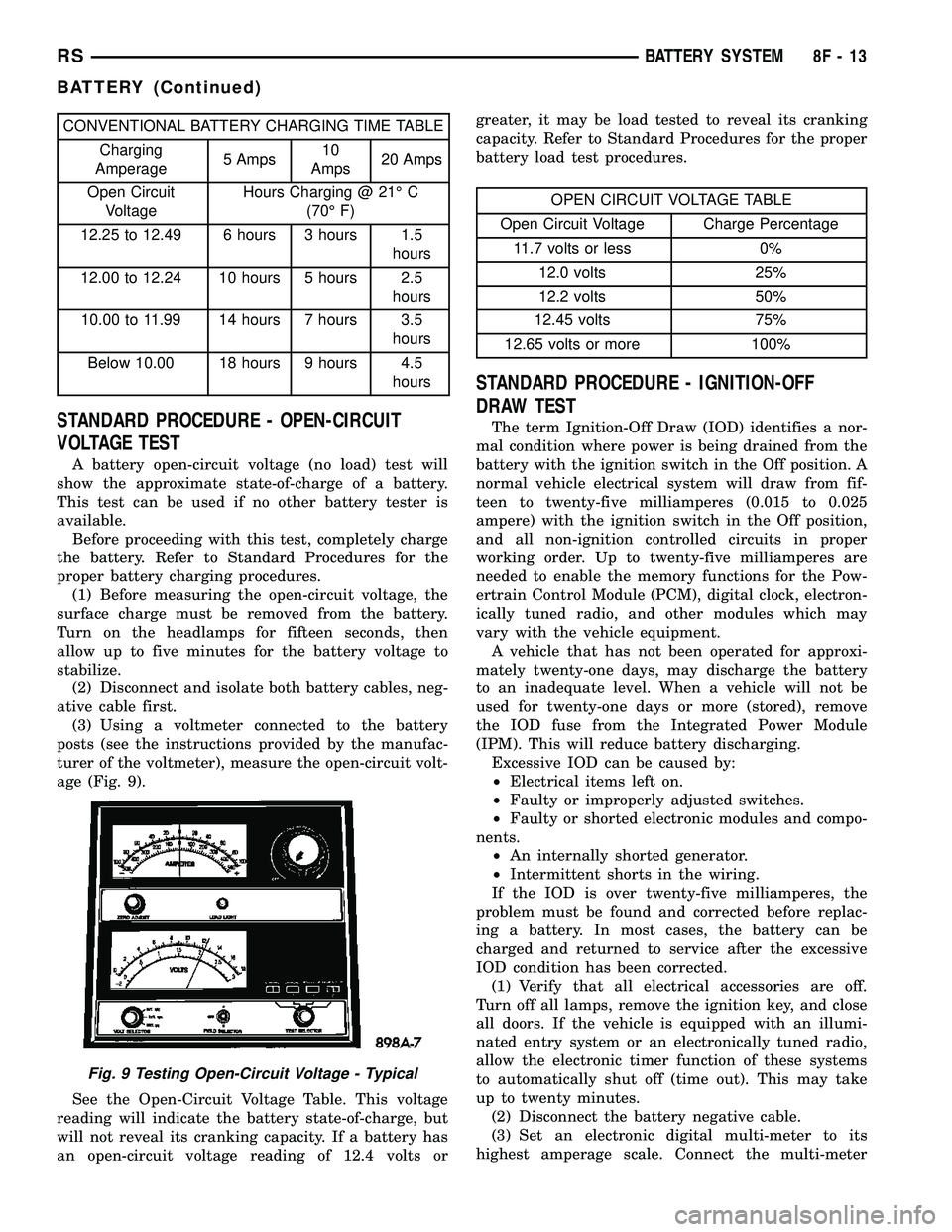
CONVENTIONAL BATTERY CHARGING TIME TABLE
Charging
Amperage5 Amps10
Amps20 Amps
Open Circuit
VoltageHours Charging @ 21É C
(70É F)
12.25 to 12.49 6 hours 3 hours 1.5
hours
12.00 to 12.24 10 hours 5 hours 2.5
hours
10.00 to 11.99 14 hours 7 hours 3.5
hours
Below 10.00 18 hours 9 hours 4.5
hours
STANDARD PROCEDURE - OPEN-CIRCUIT
VOLTAGE TEST
A battery open-circuit voltage (no load) test will
show the approximate state-of-charge of a battery.
This test can be used if no other battery tester is
available.
Before proceeding with this test, completely charge
the battery. Refer to Standard Procedures for the
proper battery charging procedures.
(1) Before measuring the open-circuit voltage, the
surface charge must be removed from the battery.
Turn on the headlamps for fifteen seconds, then
allow up to five minutes for the battery voltage to
stabilize.
(2) Disconnect and isolate both battery cables, neg-
ative cable first.
(3) Using a voltmeter connected to the battery
posts (see the instructions provided by the manufac-
turer of the voltmeter), measure the open-circuit volt-
age (Fig. 9).
See the Open-Circuit Voltage Table. This voltage
reading will indicate the battery state-of-charge, but
will not reveal its cranking capacity. If a battery has
an open-circuit voltage reading of 12.4 volts orgreater, it may be load tested to reveal its cranking
capacity. Refer to Standard Procedures for the proper
battery load test procedures.
OPEN CIRCUIT VOLTAGE TABLE
Open Circuit Voltage Charge Percentage
11.7 volts or less 0%
12.0 volts 25%
12.2 volts 50%
12.45 volts 75%
12.65 volts or more 100%
STANDARD PROCEDURE - IGNITION-OFF
DRAW TEST
The term Ignition-Off Draw (IOD) identifies a nor-
mal condition where power is being drained from the
battery with the ignition switch in the Off position. A
normal vehicle electrical system will draw from fif-
teen to twenty-five milliamperes (0.015 to 0.025
ampere) with the ignition switch in the Off position,
and all non-ignition controlled circuits in proper
working order. Up to twenty-five milliamperes are
needed to enable the memory functions for the Pow-
ertrain Control Module (PCM), digital clock, electron-
ically tuned radio, and other modules which may
vary with the vehicle equipment.
A vehicle that has not been operated for approxi-
mately twenty-one days, may discharge the battery
to an inadequate level. When a vehicle will not be
used for twenty-one days or more (stored), remove
the IOD fuse from the Integrated Power Module
(IPM). This will reduce battery discharging.
Excessive IOD can be caused by:
²Electrical items left on.
²Faulty or improperly adjusted switches.
²Faulty or shorted electronic modules and compo-
nents.
²An internally shorted generator.
²Intermittent shorts in the wiring.
If the IOD is over twenty-five milliamperes, the
problem must be found and corrected before replac-
ing a battery. In most cases, the battery can be
charged and returned to service after the excessive
IOD condition has been corrected.
(1) Verify that all electrical accessories are off.
Turn off all lamps, remove the ignition key, and close
all doors. If the vehicle is equipped with an illumi-
nated entry system or an electronically tuned radio,
allow the electronic timer function of these systems
to automatically shut off (time out). This may take
up to twenty minutes.
(2) Disconnect the battery negative cable.
(3) Set an electronic digital multi-meter to its
highest amperage scale. Connect the multi-meter
Fig. 9 Testing Open-Circuit Voltage - Typical
RSBATTERY SYSTEM8F-13
BATTERY (Continued)
Page 435 of 2585

between the disconnected battery negative cable ter-
minal clamp and the battery negative terminal post.
Make sure that the doors remain closed so that the
illuminated entry system is not activated. The multi-
meter amperage reading may remain high for up to
three minutes, or may not give any reading at all
while set in the highest amperage scale, depending
upon the electrical equipment in the vehicle. The
multi-meter leads must be securely clamped to the
battery negative cable terminal clamp and the bat-
tery negative terminal post. If continuity between the
battery negative terminal post and the negative cable
terminal clamp is lost during any part of the IOD
test, the electronic timer function will be activated
and all of the tests will have to be repeated.
(4) After about three minutes, the high-amperage
IOD reading on the multi-meter should become very
low or nonexistent, depending upon the electrical
equipment in the vehicle. If the amperage reading
remains high, remove and replace each fuse or circuit
breaker in the Integrated Power Module (IPM), one
at a time until the amperage reading becomes very
low, or nonexistent. Refer to the appropriate wiring
information in this service manual for complete Inte-
grated Power Module fuse, circuit breaker, and cir-
cuit identification. This will isolate each circuit and
identify the circuit that is the source of the high-am-
perage IOD. If the amperage reading remains high
after removing and replacing each fuse and circuit
breaker, disconnect the wire harness from the gener-
ator. If the amperage reading now becomes very low
or nonexistent, refer to Charging System for the
proper charging system diagnosis and testing proce-
dures. After the high-amperage IOD has been cor-
rected, switch the multi-meter to progressively lower
amperage scales and, if necessary, repeat the fuse
and circuit breaker remove-and-replace process to
identify and correct all sources of excessive IOD. It is
now safe to select the lowest milliampere scale of the
multi-meter to check the low-amperage IOD.
CAUTION: Do not open any doors, or turn on any
electrical accessories with the lowest milliampere
scale selected, or the multi-meter may be damaged.
(5) Allow twenty minutes for the IOD to stabilize
and observe the multi-meter reading. The low-amper-
age IOD should not exceed twenty-five milliamperes
(0.025 ampere). If the current draw exceeds twenty-
five milliamperes, isolate each circuit using the fuse
and circuit breaker remove-and-replace process in
Step 4. The multi-meter reading will drop to within
the acceptable limit when the source of the excessive
current draw is disconnected. Repair this circuit as
required; whether a wiring short, incorrect switch
adjustment, or a component failure is at fault.STANDARD PROCEDURE - CHECKING BATTERY
ELECTROLYTE LEVEL
The following procedure can be used to check the
electrolyte level in a low-maintenance lead-acid bat-
tery.
(1) Unscrew and remove the battery cell caps with
a flat-bladed screw driver (Fig. 10).
WARNING: NEVER PUT YOUR FACE NEAR A GAS-
SING, HOT OR SWELLED BATTERY. SERIOUS PER-
SONAL INJURY MAY RESULT.
(2) Wearing safety glasses, look through the bat-
tery cell cap holes to determine the level of the elec-
trolyte in the battery. The electrolyte should be above
the hooks inside the battery cells (Fig. 11).
(3)Add only distilled wateruntil the electrolyte
is above the hooks inside the battery cells (Fig. 11).
Fig. 10 BATTERY CELL CAP REMOVAL/
INSTALLATION - LOW-MAINTENANCE BATTERY
ONLY
1 - BATTERY CELL CAP
2 - BATTERY CASE
8F - 14 BATTERY SYSTEMRS
BATTERY (Continued)