differential CHRYSLER VOYAGER 2004 Workshop Manual
[x] Cancel search | Manufacturer: CHRYSLER, Model Year: 2004, Model line: VOYAGER, Model: CHRYSLER VOYAGER 2004Pages: 2585, PDF Size: 62.54 MB
Page 1638 of 2585
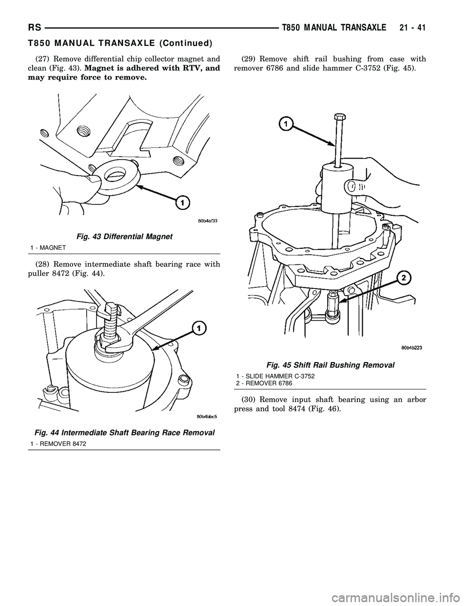
(27) Remove differential chip collector magnet and
clean (Fig. 43).Magnet is adhered with RTV, and
may require force to remove.
(28) Remove intermediate shaft bearing race with
puller 8472 (Fig. 44).(29) Remove shift rail bushing from case with
remover 6786 and slide hammer C-3752 (Fig. 45).
(30) Remove input shaft bearing using an arbor
press and tool 8474 (Fig. 46).
Fig. 43 Differential Magnet
1 - MAGNET
Fig. 44 Intermediate Shaft Bearing Race Removal
1 - REMOVER 8472
Fig. 45 Shift Rail Bushing Removal
1 - SLIDE HAMMER C-3752
2 - REMOVER 6786
RST850 MANUAL TRANSAXLE21-41
T850 MANUAL TRANSAXLE (Continued)
Page 1639 of 2585
ASSEMBLY
NOTE: When assembling this transaxle, always use
NEW snap rings.
NOTE: Before assembling transaxle, differential
turning torque must be measured and adjusted.
(Refer to 21 - TRANSMISSION/TRANSAXLE/MANU-
AL/DIFFERENTIAL - ADJUSTMENTS). Differential
turning torque must be measured with geartrain out
of case.
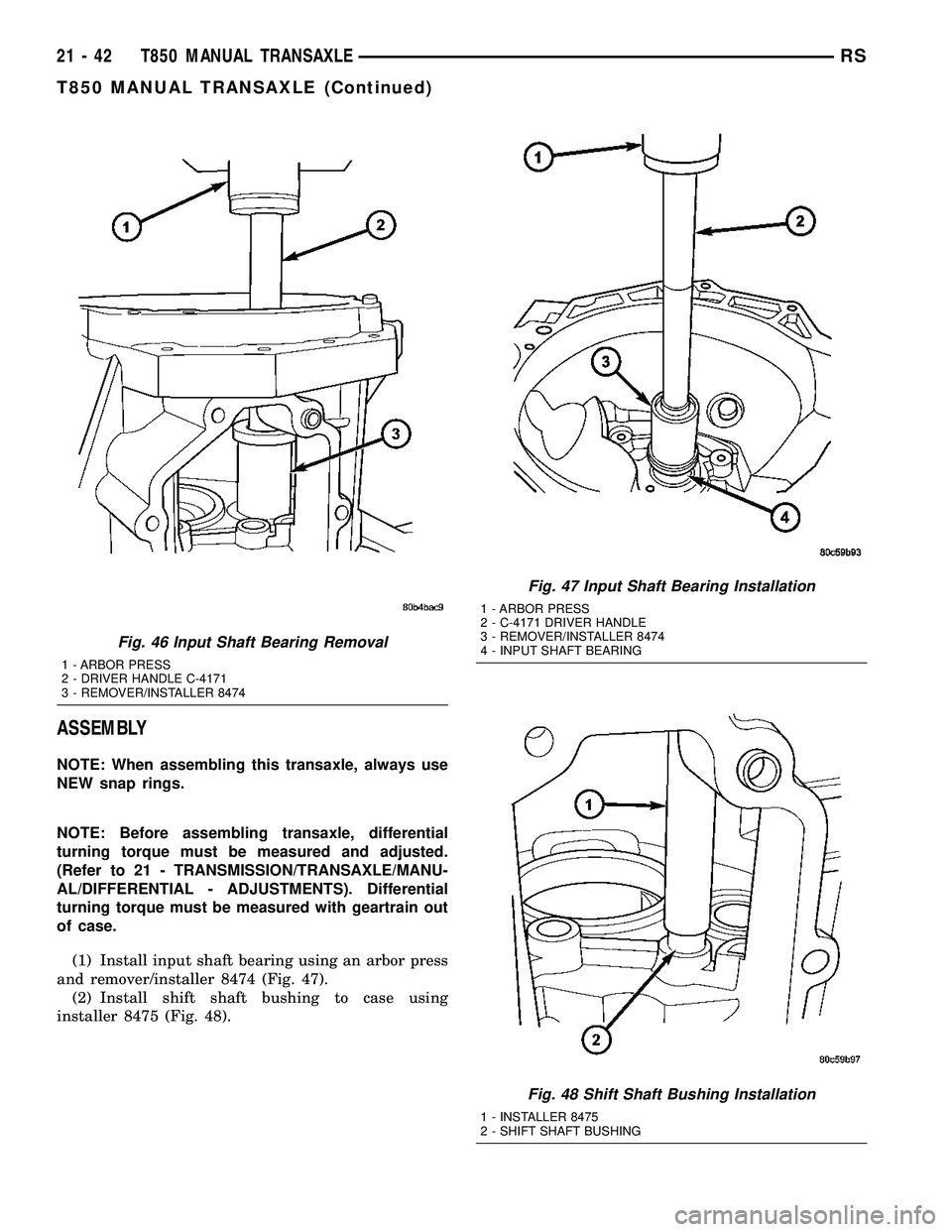
(1) Install input shaft bearing using an arbor press
and remover/installer 8474 (Fig. 47).
(2) Install shift shaft bushing to case using
installer 8475 (Fig. 48).
Fig. 46 Input Shaft Bearing Removal
1 - ARBOR PRESS
2 - DRIVER HANDLE C-4171
3 - REMOVER/INSTALLER 8474
Fig. 47 Input Shaft Bearing Installation
1 - ARBOR PRESS
2 - C-4171 DRIVER HANDLE
3 - REMOVER/INSTALLER 8474
4 - INPUT SHAFT BEARING
Fig. 48 Shift Shaft Bushing Installation
1 - INSTALLER 8475
2 - SHIFT SHAFT BUSHING
21 - 42 T850 MANUAL TRANSAXLERS
T850 MANUAL TRANSAXLE (Continued)
Page 1645 of 2585
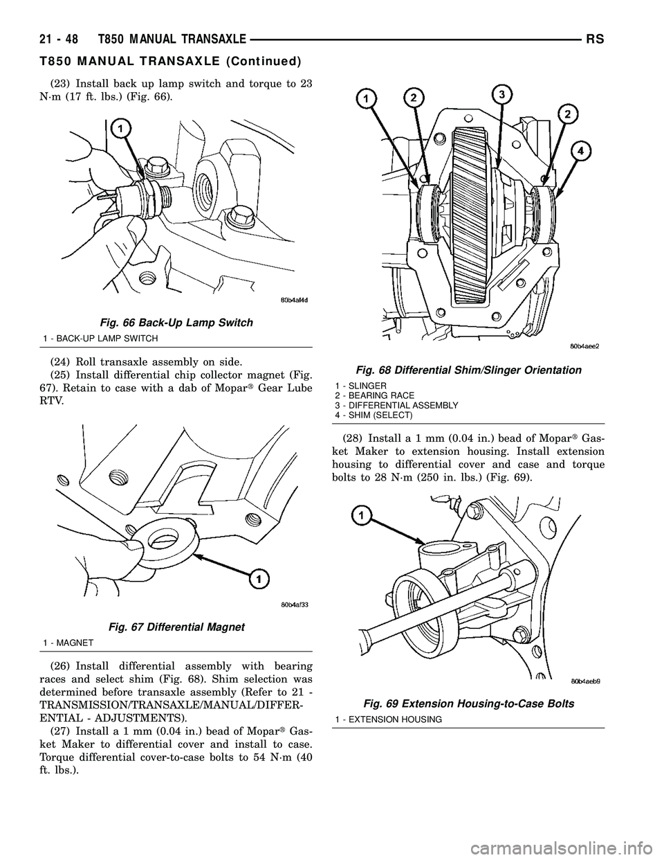
(23) Install back up lamp switch and torque to 23
N´m (17 ft. lbs.) (Fig. 66).
(24) Roll transaxle assembly on side.
(25) Install differential chip collector magnet (Fig.
67). Retain to case with a dab of MopartGear Lube
RTV.
(26) Install differential assembly with bearing
races and select shim (Fig. 68). Shim selection was
determined before transaxle assembly (Refer to 21 -
TRANSMISSION/TRANSAXLE/MANUAL/DIFFER-
ENTIAL - ADJUSTMENTS).
(27) Installa1mm(0.04 in.) bead of MopartGas-
ket Maker to differential cover and install to case.
Torque differential cover-to-case bolts to 54 N´m (40
ft. lbs.).(28) Installa1mm(0.04 in.) bead of MopartGas-
ket Maker to extension housing. Install extension
housing to differential cover and case and torque
bolts to 28 N´m (250 in. lbs.) (Fig. 69).
Fig. 66 Back-Up Lamp Switch
1 - BACK-UP LAMP SWITCH
Fig. 67 Differential Magnet
1 - MAGNET
Fig. 68 Differential Shim/Slinger Orientation
1 - SLINGER
2 - BEARING RACE
3 - DIFFERENTIAL ASSEMBLY
4 - SHIM (SELECT)
Fig. 69 Extension Housing-to-Case Bolts
1 - EXTENSION HOUSING
21 - 48 T850 MANUAL TRANSAXLERS
T850 MANUAL TRANSAXLE (Continued)
Page 1648 of 2585

INSTALLATION
INSTALLATION - 2.4L GAS
(1) Install modular clutch assembly to transaxle.
Assemble transaxle to engine.
(2) Install and torque transaxle-to-engine bolts to
95 N´m (70 ft. lbs.).
(3) Raise transaxle/engine assembly into position
and install upper mount through-bolt. Torque
through-bolt to 75 N´m (55 ft. lbs.).
(4) Remove screw jack.
(5) Install and torque modular clutch assembly-to-
drive plate bolts to 88 N´m (65 ft. lbs.)
(6) Install structural collar.
(7) Connect back-up lamp switch connector.
(8) Install starter motor into position (Fig. 78).
Install and torque bolts to 54 N´m (40 ft. lbs.).
(9) Install engine front mount bracket. Install and
torque bracket-to-transaxle bolts to 102 N´m (75 ft.
lbs.). Install and torque bracket-to-engine bolts to 68
N´m (50 ft. lbs.). Torque through-bolt and nut to 68
N´m (50 ft. lbs.).(10) Install clutch slave cylinder into position, not-
ing orientation of different sized lugs (Fig. 79). While
depressing inward, rotate slave cylinder clockwise
60tÉ into position until nylon locating tab rests
within transaxle case cutout, and hydraulic tube is
vertical. Connect ªquick-connectº connection until an
audible ªclickº is heard. Verify connection by pulling
outward on connection.
(11) Install halfshafts and front wheel/tire assem-
blies. (Refer to 3 - DIFFERENTIAL & DRIVELINE/
HALF SHAFT - INSTALLATION)
(12) Lower vehicle.
Fig. 78 Starter Motor Removal/Installation
1 - STARTER MOTOR
2 - BOLT (3)
Fig. 79 Slave Cylinder Removal/Installation
1 - MOUNTING HOLE
2 - SLAVE CYLINDER
3 - ACCESS HOLE
4 - NYLON ANTI-ROTATION TAB
5 - QUICK CONNECT
RST850 MANUAL TRANSAXLE21-51
T850 MANUAL TRANSAXLE (Continued)
Page 1651 of 2585

(8) Install engine front mount bracket. Install and
torque bracket-to-transaxle bolts to 102 N´m (75 ft.
lbs.). Install and torque bracket-to-engine bolts to 68
N´m (50 ft. lbs.). Torque through-bolt and nut to 68
N´m (50 ft. lbs.).
(9) Install clutch slave cylinder into position, not-
ing orientation of different sized lugs (Fig. 85). While
depressing inward, rotate slave cylinder clockwise
60É into position until nylon locating tab rests within
transaxle case cutout, and hydraulic tube is vertical.
Connect ªquick-connectº connection until an audible
ªclickº is heard. Verify connection by pulling outward
on connection.
(10) Install underbody splash panel.
(11) Install halfshafts and front wheel/tire assem-
blies. (Refer to 3 - DIFFERENTIAL & DRIVELINE/
HALF SHAFT - INSTALLATION)
(12) Lower vehicle.
(13) Install right mount bracket to transaxle (Fig.
86).
(14) Connect gearshift cables to shift levers/cover
assembly (Fig. 87). Install cables into position at
mount bracket and secure with retaining clips.
Fig. 85 Slave Cylinder Removal/Installation
1 - MOUNTING HOLE
2 - SLAVE CYLINDER
3 - ACCESS HOLE
4 - NYLON ANTI-ROTATION TAB
5 - QUICK CONNECT
Fig. 86 Transaxle Right Mount and Bracket
1 - MOUNT BRACKET
2 - BOLT (3)
3 - MOUNT
4 - BOLT (1)
Fig. 87 Gearshift Cables at Transaxle
1 - SELECTOR CABLE
2 - CABLE RETAINER
3 - CABLE RETAINER
4 - CROSSOVER CABLE
5 - MOUNT BRACKET
21 - 54 T850 MANUAL TRANSAXLERS
T850 MANUAL TRANSAXLE (Continued)
Page 1653 of 2585
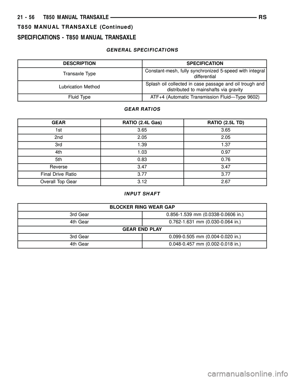
SPECIFICATIONS - T850 MANUAL TRANSAXLE
GENERAL SPECIFICATIONS
DESCRIPTION SPECIFICATION
Transaxle TypeConstant-mesh, fully synchronized 5-speed with integral
differential
Lubrication MethodSplash oil collected in case passage and oil trough and
distributed to mainshafts via gravity
Fluid Type ATF+4 (Automatic Transmission FluidÐType 9602)
GEAR RATIOS
GEAR RATIO (2.4L Gas) RATIO (2.5L TD)
1st 3.65 3.65
2nd 2.05 2.05
3rd 1.39 1.37
4th 1.03 0.97
5th 0.83 0.76
Reverse 3.47 3.47
Final Drive Ratio 3.77 3.77
Overall Top Gear 3.12 2.67
INPUT SHAFT
BLOCKER RING WEAR GAP
3rd Gear 0.856-1.539 mm (0.0338-0.0606 in.)
4th Gear 0.762-1.631 mm (0.030-0.064 in.)
GEAR END PLAY
3rd Gear 0.099-0.505 mm (0.004-0.020 in.)
4th Gear 0.048-0.457 mm (0.002-0.018 in.)
21 - 56 T850 MANUAL TRANSAXLERS
T850 MANUAL TRANSAXLE (Continued)
Page 1654 of 2585
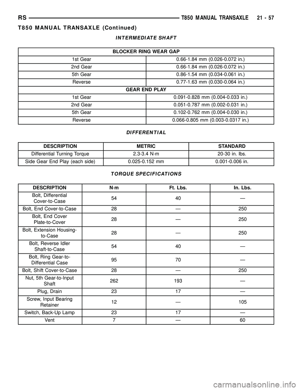
INTERMEDIATE SHAFT
BLOCKER RING WEAR GAP
1st Gear 0.66-1.84 mm (0.026-0.072 in.)
2nd Gear 0.66-1.84 mm (0.026-0.072 in.)
5th Gear 0.86-1.54 mm (0.034-0.061 in.)
Reverse 0.77-1.63 mm (0.030-0.064 in.)
GEAR END PLAY
1st Gear 0.091-0.828 mm (0.004-0.033 in.)
2nd Gear 0.051-0.787 mm (0.002-0.031 in.)
5th Gear 0.102-0.762 mm (0.004-0.030 in.)
Reverse 0.066-0.805 mm (0.003-0.0317 in.)
DIFFERENTIAL
DESCRIPTION METRIC STANDARD
Differential Turning Torque 2.3-3.4 N´m 20-30 in. lbs.
Side Gear End Play (each side) 0.025-0.152 mm 0.001-0.006 in.
TORQUE SPECIFICATIONS
DESCRIPTION N´m Ft. Lbs. In. Lbs.
Bolt, Differential
Cover-to-Case54 40 Ð
Bolt, End Cover-to-Case 28 Ð 250
Bolt, End Cover
Plate-to-Cover28 Ð 250
Bolt, Extension Housing-
to-Case28 Ð 250
Bolt, Reverse Idler
Shaft-to-Case54 40 Ð
Bolt, Ring Gear-to-
Differential Case95 70 Ð
Bolt, Shift Cover-to-Case 28 Ð 250
Nut, 5th Gear-to-Input
Shaft262 193 Ð
Plug, Drain 23 17 Ð
Screw, Input Bearing
Retainer12 Ð 105
Switch, Back-Up Lamp 23 17 Ð
Vent 7 Ð 60
RST850 MANUAL TRANSAXLE21-57
T850 MANUAL TRANSAXLE (Continued)
Page 1658 of 2585
AXLE SEALS
REMOVAL
(1) Raise vehicle on hoist.
(2) Remove one or both front halfshaft assemblies.
(Refer to 3 - DIFFERENTIAL & DRIVELINE/HALF
SHAFT - REMOVAL)
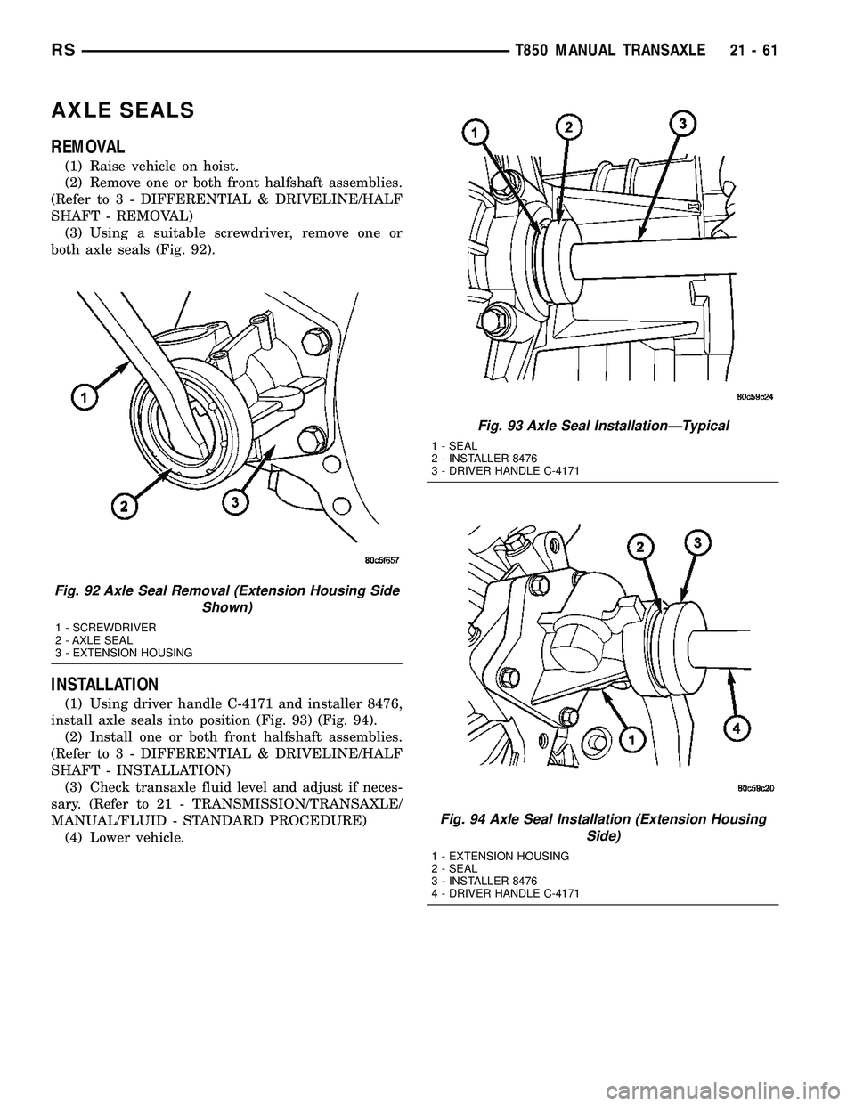
(3) Using a suitable screwdriver, remove one or
both axle seals (Fig. 92).
INSTALLATION
(1) Using driver handle C-4171 and installer 8476,
install axle seals into position (Fig. 93) (Fig. 94).
(2) Install one or both front halfshaft assemblies.
(Refer to 3 - DIFFERENTIAL & DRIVELINE/HALF
SHAFT - INSTALLATION)
(3) Check transaxle fluid level and adjust if neces-
sary. (Refer to 21 - TRANSMISSION/TRANSAXLE/
MANUAL/FLUID - STANDARD PROCEDURE)
(4) Lower vehicle.
Fig. 92 Axle Seal Removal (Extension Housing Side
Shown)
1 - SCREWDRIVER
2 - AXLE SEAL
3 - EXTENSION HOUSING
Fig. 93 Axle Seal InstallationÐTypical
1 - SEAL
2 - INSTALLER 8476
3 - DRIVER HANDLE C-4171
Fig. 94 Axle Seal Installation (Extension Housing
Side)
1 - EXTENSION HOUSING
2 - SEAL
3 - INSTALLER 8476
4 - DRIVER HANDLE C-4171
RST850 MANUAL TRANSAXLE21-61
Page 1659 of 2585
BACK-UP LAMP SWITCH
REMOVAL
(1) Raise vehicle on hoist.
(2) Disconnect back-up lamp switch connector.
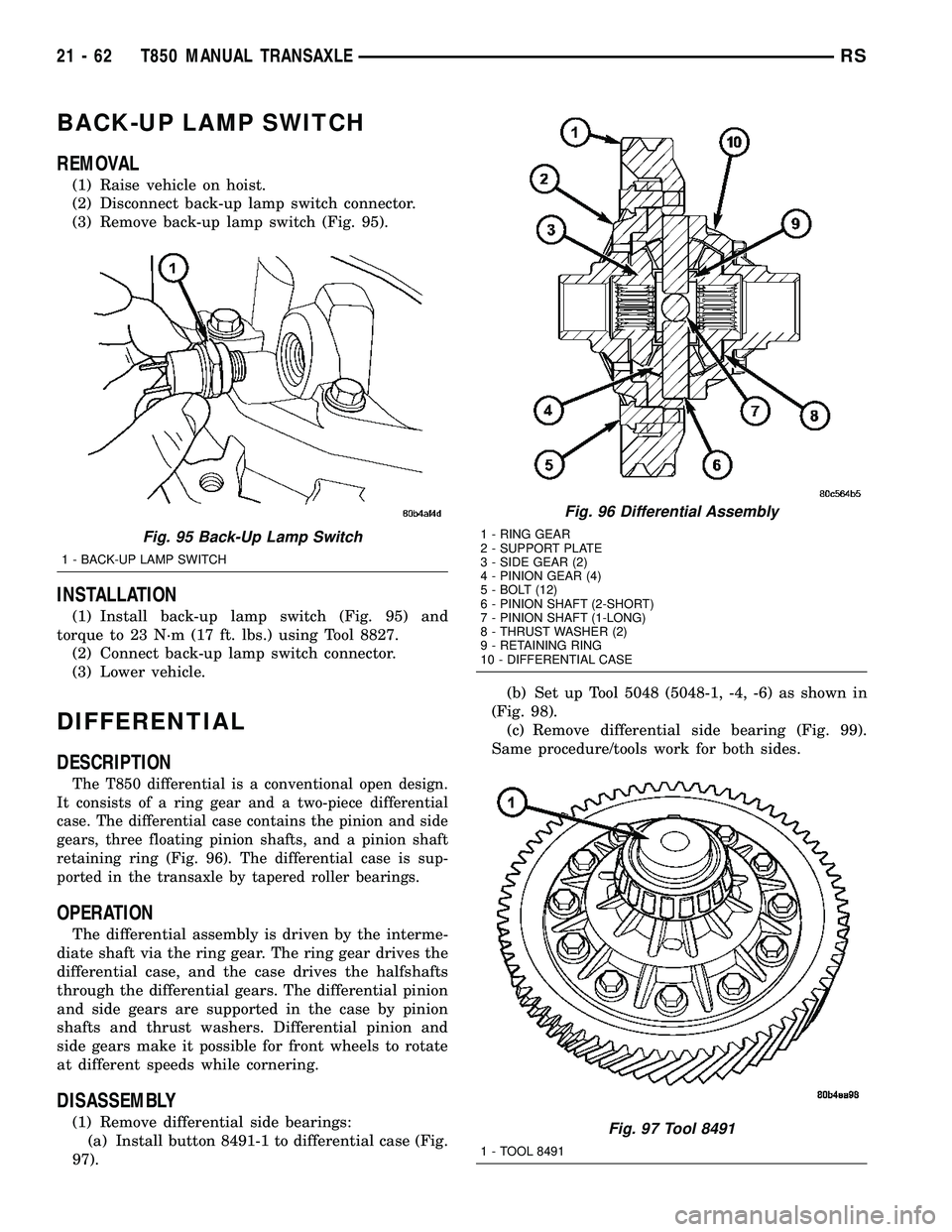
(3) Remove back-up lamp switch (Fig. 95).
INSTALLATION
(1) Install back-up lamp switch (Fig. 95) and
torque to 23 N´m (17 ft. lbs.) using Tool 8827.
(2) Connect back-up lamp switch connector.
(3) Lower vehicle.
DIFFERENTIAL
DESCRIPTION
The T850 differential is a conventional open design.
It consists of a ring gear and a two-piece differential
case. The differential case contains the pinion and side
gears, three floating pinion shafts, and a pinion shaft
retaining ring (Fig. 96). The differential case is sup-
ported in the transaxle by tapered roller bearings.
OPERATION
The differential assembly is driven by the interme-
diate shaft via the ring gear. The ring gear drives the
differential case, and the case drives the halfshafts
through the differential gears. The differential pinion
and side gears are supported in the case by pinion
shafts and thrust washers. Differential pinion and
side gears make it possible for front wheels to rotate
at different speeds while cornering.
DISASSEMBLY
(1) Remove differential side bearings:
(a) Install button 8491-1 to differential case (Fig.
97).(b) Set up Tool 5048 (5048-1, -4, -6) as shown in
(Fig. 98).
(c) Remove differential side bearing (Fig. 99).
Same procedure/tools work for both sides.
Fig. 95 Back-Up Lamp Switch
1 - BACK-UP LAMP SWITCH
Fig. 96 Differential Assembly
1 - RING GEAR
2 - SUPPORT PLATE
3 - SIDE GEAR (2)
4 - PINION GEAR (4)
5 - BOLT (12)
6 - PINION SHAFT (2-SHORT)
7 - PINION SHAFT (1-LONG)
8 - THRUST WASHER (2)
9 - RETAINING RING
10 - DIFFERENTIAL CASE
Fig. 97 Tool 8491
1 - TOOL 8491
21 - 62 T850 MANUAL TRANSAXLERS
Page 1660 of 2585
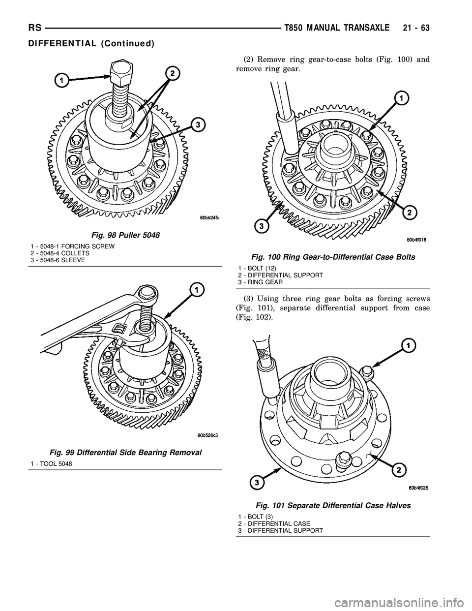
(2) Remove ring gear-to-case bolts (Fig. 100) and
remove ring gear.
(3) Using three ring gear bolts as forcing screws
(Fig. 101), separate differential support from case
(Fig. 102).
Fig. 98 Puller 5048
1 - 5048-1 FORCING SCREW
2 - 5048-4 COLLETS
3 - 5048-6 SLEEVE
Fig. 99 Differential Side Bearing Removal
1 - TOOL 5048
Fig. 100 Ring Gear-to-Differential Case Bolts
1 - BOLT (12)
2 - DIFFERENTIAL SUPPORT
3 - RING GEAR
Fig. 101 Separate Differential Case Halves
1 - BOLT (3)
2 - DIFFERENTIAL CASE
3 - DIFFERENTIAL SUPPORT
RST850 MANUAL TRANSAXLE21-63
DIFFERENTIAL (Continued)