fuse CHRYSLER VOYAGER 2004 Workshop Manual
[x] Cancel search | Manufacturer: CHRYSLER, Model Year: 2004, Model line: VOYAGER, Model: CHRYSLER VOYAGER 2004Pages: 2585, PDF Size: 62.54 MB
Page 621 of 2585
POWER SEAT SYSTEM
TABLE OF CONTENTS
page page
POWER SEAT SYSTEM
DESCRIPTION
DESCRIPTION........................50
DESCRIPTION - MEMORY SYSTEM.......51
OPERATION
OPERATION - POWER SEAT SYSTEM.....52
OPERATION - MEMORY SYSTEM.........52
DIAGNOSIS AND TESTING
DIAGNOSIS AND TESTING - POWER SEAT
SYSTEM............................52
DIAGNOSIS AND TESTING - MEMORY
SYSTEM............................53
DRIVER SEAT SWITCH
DESCRIPTION.........................53
OPERATION...........................54
DIAGNOSIS AND TESTING - DRIVER SEAT
SWITCH............................54
REMOVAL.............................55
INSTALLATION.........................55
MEMORY SET SWITCH
DESCRIPTION.........................55
OPERATION...........................56
DIAGNOSIS AND TESTING - MEMORY
SWITCH............................56REMOVAL.............................56
INSTALLATION.........................56
PASSENGER SEAT SWITCH
DESCRIPTION.........................56
OPERATION...........................56
DIAGNOSIS AND TESTING - PASSENGER
SEAT SWITCH........................57
REMOVAL.............................57
INSTALLATION.........................57
DRIVER POWER SEAT TRACK
DESCRIPTION.........................58
OPERATION...........................58
DIAGNOSIS AND TESTING - DRIVER POWER
SEAT TRACK.........................58
REMOVAL.............................59
INSTALLATION.........................59
PASSENGER POWER SEAT TRACK
DESCRIPTION.........................59
OPERATION...........................60
DIAGNOSIS AND TESTING - POWER SEAT
TRACK.............................60
REMOVAL.............................61
INSTALLATION.........................61
POWER SEAT SYSTEM
DESCRIPTION
DESCRIPTION
The power seat system option allows the driver
and front seat passenger to electrically adjust their
seating positions for optimum control and comfort
using the power seat switches located on the out-
board seat cushion side shield of each front seat. The
driver side power front seat can be adjusted in eight
different directions: up, down, front up, front down,
rear up, rear down, forward, rearward and recliner
forward and rearward. The passenger side power
front seat can be adjusted in four different directions:
forward, rearward and recliner forward and rear-
ward.
The power seat system receives battery current
through a 40 amp fuse in the Intelligent Power Mod-
ule and a 30 amp circuit breaker under the seat so
that the power seats remain operational, regardless
of the ignition switch position.WARNING: SOME VEHICLES ARE EQUIPPED WITH
SEATBACK MOUNTED AIRBAGS (Fig. 1). BEFORE
ATTEMPTING TO DIAGNOSE OR SERVICE ANY
SEAT OR POWER SEAT SYSTEM COMPONENT
YOU MUST FIRST DISCONNECT AND ISOLATE THE
BATTERY NEGATIVE CABLE. THEN WAIT TWO MIN-
UTES FOR THE SYSTEM CAPACITOR TO DIS-
CHARGE BEFORE FURTHER SYSTEM SERVICE.
THIS IS THE ONLY SURE WAY TO DISABLE THE
AIRBAG SYSTEM. FAILURE TO DO SO COULD
RESULT IN ACCIDENTAL AIRBAG DEPLOYMENT
AND POSSIBLE PERSONAL INJURY.
A eight-way driver side power seat is standard on
highline models and optional on others. This option
includes a six-way adjustable seat cushion track and
a two-way power seat back.
The eight-way driver side power seat is also avail-
able with the heated seat and/or memory seat system
that automatically positions the power seat for two
different drivers. Refer toHeated Seatsfor more
information on the heated seat option. Refer to
Description - Memory Systemin this section for
more information on the memory seat system.
8N - 50 POWER SEAT SYSTEMRS
Page 623 of 2585
Refer toHeated Seat Systemfor more informa-
tion on the heated seat system. Refer toRemote
Keyless Entry Systemin Power Lock Systems for
more information on the RKE system.
Refer toWiring Diagramsfor complete circuit
diagrams. Following are descriptions, theory of oper-
ation, diagnosis/testing procedures and removal/in-
stallation procedures of the major components in the
memory and power seat systems.
OPERATION
OPERATION - POWER SEAT SYSTEM
The power seat system receives battery current
through fuse #22 in the Intelligent Power Module
and a circuit breaker under the front seats, regard-
less of the ignition switch position.
When a power seat switch control knob or knobs
are actuated, a battery feed and a ground path are
applied through the switch contacts to the appropri-
ate power seat track adjuster motor. The selected
adjuster motor operates to move the seat track
through its drive unit in the selected direction until
the switch is released, or until the travel limit of the
seat track is reached. When the switch is moved in
the opposite direction, the battery feed and ground
path to the motor are reversed through the switch
contacts. This causes the adjuster motor to run in the
opposite direction.
No power seat switch should be held applied in any
direction after the seat track has reached its travel
limit. The power seat track each contain a self-reset-
ting circuit breaker to protect them from overload.
However, consecutive or frequent resetting of the cir-
cuit breaker must not be allowed to continue, or the
motor may be damaged. Refer to the owner's manual
in the vehicle glove box for more information on the
features, use and operation of the power seat system.
OPERATION - MEMORY SYSTEM
The Memory Seat Mirror Module (MSMM) receives
battery current through fuse #22 in the Intelligent
Power Module and the power seat system circuit
breaker, located under the driver side front seat near
the rear edge of the seat cushion pan. The memory
system does not operate with the Ignition-Off Draw
(IOD) fuse removed. The MSMM will drive a maxi-
mum of 2 motors at a time in a given direction. If
conflicting directions are requested, the priority for
response will be approximately as follows:
²Seat Track Rearward or Forward
²Seat Front Down or Up
²Seat Rear Down or Up
²Recliner Rearward or ForwardThe inputs from these switches to the MSMM is a
current limited battery source fed by the MSMM.
This protects the MSMM printed circuit board traces
from acting as fuses. All of these switch contact
inputs to the MSMM are normally closed to ground,
except when actuated.
See the owner's manual in the vehicle glove box for
more information on the features, use and operation
of the memory system. For diagnosis of the MSMM,
the PCI data bus, or the other electronic modules on
the PCI data bus that provide inputs and outputs for
the memory system, the use of a DRBIIItscan tool
and the proper Diagnostic Procedures manual are
recommended.
ELECTRONIC VEHICLE INFORMATION CENTER
The Electronic Vehicle Information Center (EVIC)
serves as the user interface for the memory system.
It displays memory system status messages and pro-
vides the user with the means for enabling and dis-
abling the many customer programmable features
available on the vehicle, including those for the mem-
ory system.
See the owner's manual in the vehicle glove box for
more information on the features, use and operation
of the EVIC. Refer toElectronic Vehicle Informa-
tion Centerin Overhead Console Systems for more
information on the EVIC.
DIAGNOSIS AND TESTING
DIAGNOSIS AND TESTING - POWER SEAT
SYSTEM
Following are tests that will help to diagnose the
hard wired components and circuits of the power seat
system. However, if the vehicle is also equipped with
the optional memory system, these tests may not
prove conclusive in the diagnosis of the driver side
power seat. In order to obtain conclusive testing of
the driver side power seat with the memory system
option, the Programmable Communications Interface
(PCI) data bus network and all of the electronic mod-
ules that provide inputs to, or receive outputs from
the memory system components must be checked.
The most reliable, efficient, and accurate means to
diagnose the driver side power seat with the memory
system option requires the use of a DRBIIItscan tool
and the proper Diagnostic Procedures manual. The
DRBIIItscan tool can provide confirmation that the
PCI data bus is functional, that all of the electronic
modules are sending and receiving the proper mes-
sages on the PCI data bus, and that the memory sys-
tem is receiving the proper hard wired inputs and
relaying the proper hard wired outputs to perform its
driver side power seat functions.
8N - 52 POWER SEAT SYSTEMRS
POWER SEAT SYSTEM (Continued)
Page 630 of 2585
TESTING POWER SEAT TRACK MOTORS
(1) Check the power seat circuit breaker under the
seat. If OK, go to Step 2. If not OK, replace the
faulty power seat circuit breaker.
(2) Check for battery voltage at the power seat cir-
cuit breaker under the seat. If OK, go to Step 3. If
not OK, repair the open fused B(+) circuit to the fuse
in the Intelligent Power Module as required.
(3) Remove the outboard seat cushion side shield
from the seat. Disconnect the seat wire harness con-
nector from the power seat switch connector recepta-
cle. Check for battery voltage at the fused B(+)
circuit cavity of the power seat wire harness connec-
tor for the power seat switch. If OK, go to Step 4. If
not OK, repair the open fused B(+) circuit to the
power seat circuit breaker under the seat as
required.
(4) Check for continuity between the ground cir-
cuit cavity of the power seat wire harness connector
for the power seat switch and a good ground. There
should be continuity. If OK, go to Step 5. If not OK,
repair the open ground circuit to ground as required.
(5) Test the power seat switch. Refer toDiagnosis
and Testing Power Seat Switchin this section. If
the switch tests OK, test the circuits of the power
seat wire harness between the inoperative power seat
track adjuster motor and the power seat switch for
shorts or opens. If the circuits check OK, replace the
faulty power seat track unit. If the circuits are not
OK, repair the power seat wire harness as required.
REMOVAL
WARNING: SOME VEHICLES ARE EQUIPPED WITH
SEATBACK MOUNTED AIRBAGS. BEFORE
ATTEMPTING TO DIAGNOSE OR SERVICE ANY
SEAT OR POWER SEAT SYSTEM COMPONENT
YOU MUST FIRST DISCONNECT AND ISOLATE THE
BATTERY NEGATIVE CABLE. THEN WAIT TWO MIN-
UTES FOR THE SYSTEM CAPACITOR TO DIS-
CHARGE BEFORE FURTHER SYSTEM SERVICE.
THIS IS THE ONLY SURE WAY TO DISABLE THE
AIRBAG SYSTEM. FAILURE TO DO SO COULD
RESULT IN ACCIDENTAL AIRBAG DEPLOYMENT
AND POSSIBLE PERSONAL INJURY.
(1) Remove the appropriate seat from the vehicle
and place it on a clean work surface(Refer to 23 -
BODY/SEATS/SEAT - REMOVAL).
(2) If the vehicle is so equipped, remove the Mem-
ory Seat/Mirror Module (MSMM) retaining screws.
(3) If the vehicle is so equipped, disconnect the
MSMM electrical connectors and remove the MSMM
from the power seat track.
(4) Remove the rear fabric blocker trim panel from
the rear of the front seat.(5) Remove the seat side cover and power seat
switch as an assembly (Refer to 23 - BODY/SEATS/
SEAT CUSHION SIDE COVERS - REMOVAL).
(6) Disconnect all electrical connectors connecting
the power seat track to the seat assembly.
(7) Pull the seat back trim cover up slightly to
access and remove the two seat back frame mounting
bolts and also remove two seat back recliner bolts.
(8) Remove four seat track mounting bolts from
the seat cushion pan.
(9) Remove the power seat track from the seat.
INSTALLATION
(1) Position the seat cushion on the seat track.
(2) Install the four seat track retaining bolts in the
seat cushion pan. Torque the bolts to 28.5 N´m.
(3) Position the seat back and install the two seat
back frame mounting bolts and the two seat back
recliner bolts. Torque the bolts to 55 N´m.
(4) Route and connect the electrical connectors
between the power seat track and the seat assembly.
(5) Install the seat side cover and power seat
switch as an assembly (Refer to 23 - BODY/SEATS/
SEAT CUSHION SIDE COVERS - INSTALLATION).
(6) Install the rear fabric blocker trim panel on the
rear of the front seat.
(7) If the vehicle is so equipped, position the Mem-
ory Seat/Mirror Module (MSMM) and connect the
MSMM electrical connectors.
(8) Install the MSMM retaining screws.
(9) Install the seat assembly in the vehicle (Refer
to 23 - BODY/SEATS/SEAT - INSTALLATION).
PASSENGER POWER SEAT
TRACK
DESCRIPTION
The four-way passenger side power seat option
includes a electrically operated power seat track unit
located under the passenger side front seat. The
power seat circuit breaker is mounted on the rear of
the power seat track, just behind the seat rear trim
panel. The lower half of the power seat track is
secured to the floor panel via four studs and nuts
that must be accessed from the underside of the vehi-
cle. Four bolts secure the bottom of the seat cushion
frame to the upper half of the power seat track unit.
Four additional bolts secure the seat back frame to
the power seat track unit.
The passenger side power seat track unit includes
two reversible electric motors that are secured to the
upper half of the track unit. Each motor moves the
seat adjuster through a combination of worm-drive
gearboxes and screw-type drive units. The horizontal
adjustment motor moves the seat track in the for-
RSPOWER SEAT SYSTEM8N-59
DRIVER POWER SEAT TRACK (Continued)
Page 631 of 2585
ward and rearward directions. The recliner adjust-
ment motor moves the seat back in the forward and
rearward directions.
The power seat track unit cannot be repaired, and
is serviced only as a complete unit. If any component
in this unit is faulty or damaged, the entire power
seat track unit must be replaced.
OPERATION
When a passenger side power seat switch control
knob or knobs are actuated, a battery feed and a
ground path are applied through the switch contacts
to the power seat track or recliner adjuster motor.
The selected adjuster motor operates to move the
seat track or recliner through its drive unit in the
selected direction until the switch is released, or
until the travel limit of the adjuster is reached.
When the switch is moved in the opposite direction,
the battery feed and ground path to the motor are
reversed through the switch contacts. This causes the
adjuster motor to run in the opposite direction.
No power seat switch should be held applied in any
direction after the adjuster has reached its travel
limit. The power seat adjuster motors each contain a
self-resetting circuit breaker to protect them from
overload. However, consecutive or frequent resetting
of the circuit breaker must not be allowed to con-
tinue, or the motor may be damaged.
See the owner's manual in the vehicle glove box for
more information on the power seat switch functions
and the seat adjusting procedures.
DIAGNOSIS AND TESTING - POWER SEAT
TRACK
WARNING: SOME VEHICLES ARE EQUIPPED WITH
SEATBACK MOUNTED AIRBAGS. BEFORE
ATTEMPTING TO DIAGNOSE OR SERVICE ANY
SEAT OR POWER SEAT SYSTEM COMPONENT
YOU MUST FIRST DISCONNECT AND ISOLATE THE
BATTERY NEGATIVE CABLE. THEN WAIT TWO MIN-
UTES FOR THE SYSTEM CAPACITOR TO DIS-
CHARGE BEFORE FURTHER SYSTEM SERVICE.
THIS IS THE ONLY SURE WAY TO DISABLE THE
AIRBAG SYSTEM. FAILURE TO DO SO COULDRESULT IN ACCIDENTAL AIRBAG DEPLOYMENT
AND POSSIBLE PERSONAL INJURY.
Actuate the passenger side power seat switch to
move the power seat track adjuster in each direction.
The power seat track adjuster should move in each of
the selected directions. If a power seat track adjuster
fails to operate in only one direction, move the
adjuster a short distance in the opposite direction
and test again to be certain that the adjuster is not
at its travel limit. If the power seat track adjuster
still fails to operate in only one direction, refer to
Diagnosis and Testing Power Seat Switchin this
section. If the power seat track adjuster fails to oper-
ate in more than one direction, perform the following
tests. For complete circuit diagrams, refer toWiring
Diagrams.
(1) Check the power seat circuit breaker under the
seat. If OK, go to Step 2. If not OK, replace the
faulty power seat circuit breaker.
(2) Check for battery voltage at the power seat cir-
cuit breaker under the seat. If OK, go to Step 3. If
not OK, repair the open fused B(+) circuit to the fuse
in the Intelligent Power Module as required.
(3) Remove the outboard seat cushion side shield
from the seat. Disconnect the seat wire harness con-
nector from the power seat switch connector recepta-
cle. Check for battery voltage at the fused B(+)
circuit cavity of the power seat wire harness connec-
tor for the power seat switch. If OK, go to Step 4. If
not OK, repair the open fused B(+) circuit to the
power seat circuit breaker under the seat as
required.
(4) Check for continuity between the ground cir-
cuit cavity of the power seat wire harness connector
for the power seat switch and a good ground. There
should be continuity. If OK, go to Step 5. If not OK,
repair the open ground circuit to ground as required.
(5) Test the power seat switch. Refer toDiagnosis
and Testing Power Seat Switchin this section. If
the switch tests OK, test the circuits of the power
seat wire harness between the inoperative power seat
track adjuster motor and the power seat switch for
shorts or opens. If the circuits check OK, replace the
faulty power seat track unit. If the circuits are not
OK, repair the power seat wire harness as required.
8N - 60 POWER SEAT SYSTEMRS
PASSENGER POWER SEAT TRACK (Continued)
Page 634 of 2585

WIRING VOLTAGE TEST
The following wiring test determines whether or
not voltage is continuous through the body harness
to switch.
(1) Remove the power window switch and bezel
assembly from the driver door. (Refer to 8 - ELEC-
TRICAL/POWER WINDOWS/POWER WINDOW
SWITCH - REMOVAL).
(2) Disconnect wire connector from back of power
window switch.
(3) Switch ignition ON position.
(4) Connect the clip end of a 12 volt test light to
Pin 13 in door harness connector at the window
switch. Touch the test light probe to Pin 9 and then
to Pin 11.
²If the test light illuminates, the wiring circuit
between the battery and switch is OK.
²If the lamp does not illuminate, first check the
25 amp circuit breaker attached to the electrical dis-
tribution wiring bracket. If the circuit breaker is OK,
then check the 40 amp fuse (#28) in the Integrated
Power Module (IPM). If both components are OK,
then check for a broken wire.
²Refer to the appropriate wiring information.
The wiring information includes wiring diagrams,
proper wire and connector repair procedures, details
of wire harness routing and retention, connector pin-
out information and location views for the various
wire harness connectors, splices and grounds.
VENT WINDOW MOTOR
DIAGNOSIS AND TESTING - VENT WINDOW
MOTOR
If the power vent window motor is receiving proper
current and ground and does not operate proceed
with motor test. Refer to the appropriate wiring
information. The wiring information includes wiring
diagrams, proper wire and connector repair proce-
dures, details of wire harness routing and retention,
connector pin-out information and location views for
the various wire harness connectors, splices and
grounds.
(1) Remove D-pillar trim panel necessary to gain
access to power vent window motor wire connector,
(Refer to 23 - BODY/INTERIOR/LEFT D-PILLAR
TRIM PANEL - REMOVAL) or (Refer to 23 - BODY/
INTERIOR/RIGHT D-PILLAR TRIM PANEL -
REMOVAL).
(2) Disconnect power vent window motor wire con-
nector from body harness.
(3) Using two jumper wires, connect one to a bat-
tery (+) source and the other to a good ground (-).
(4) Connect the Negative (-) jumper probe to one of
the motor connector terminals.(5) Momentarily touch the Positive (+) jumper
probe to the other motor connector terminal.
When positive probe is connected the motor should
rotate in one direction to either move window open or
closed. If window is all the way open or closed the
motor will grunt and the crank system will flex when
actuated in that one direction.
Reverse jumper probes at the motor connector ter-
minals and window should now move in opposite
direction. If window does not move or grunt, replace
the motor.
If window moved completely open or closed, reverse
the jumper probes and cycle window to the opposite
position to verify full operation.
If motor grunts and does not move, verify that
crank system is not binding.
REMOVAL
(1) Disconnect and isolate the battery negative
cable.
(2) Remove D-pillar trim panel. (Refer to 23 -
BODY/INTERIOR/LEFT D-PILLAR TRIM PANEL -
REMOVAL) or (Refer to 23 - BODY/INTERIOR/
RIGHT D-PILLAR TRIM PANEL - REMOVAL).
(3) Disconnect wire connector from power vent
motor.
(4) Using a flat bladed tool, carefully lift the circu-
lar actuator link tab. Remove link from window ball
socket.
(5) Remove bolts holding power vent motor to
D-pillar (Fig. 1).
(6) Remove power vent motor.
Fig. 1 VENT WINDOW MOTOR
1 - VENT WINDOW MOTOR
2 - WIRE HARNESS CONNECTOR
3 - BOLT
4 - VENT WINDOW
RSPOWER WINDOWS8N-63
POWER WINDOWS (Continued)
Page 638 of 2585

POWER SYSTEMS
TABLE OF CONTENTS
page page
POWER LOCKS............................ 1 POWER SEAT SYSTEM...................... 7
POWER LOCKS
TABLE OF CONTENTS
page page
POWER LOCKS DESCRIPTION ..........................1
OPERATION ............................2
DOOR CYLINDER LOCK SWITCH - EXPORT DESCRIPTION ..........................3
OPERATION ............................3
DIAGNOSIS AND TESTING - DOOR CYLINDER LOCK SWITCH - EXPORT .......3
REMOVAL .............................3
INSTALLATION ..........................4
DOOR LOCK MOTOR DIAGNOSIS AND TESTING - DOOR LOCKMOTOR ..............................4
DOOR LOCK SWITCH DIAGNOSIS AND TESTING - DOOR LOCKSWITCH .............................4
REMOVAL .............................4
INSTALLATION ..........................4 KEYLESS ENTRY TRANSMITTER
DIAGNOSIS AND TESTING - KEYLESS ENTRYTRANSMITTER ........................5
STANDARD PROCEDURE STANDARD PROCEDURE - HORN CHIRPPREFERENCE .........................5
STANDARD PROCEDURE - BATTERY REPLACEMENT .......................5
STANDARD PROCEDURE - REMOTE KEYLESS ENTRY TRANSMITTER
PROGRAMMING .......................5
SPECIFICATIONS SPECIFICATIONS - TRANSMITTER RANGE . . 5
SPECIFICATIONS - BATTERY .............5
SLIDING DOOR LOCK MOTOR REMOVAL .............................6
INSTALLATION ..........................6
POWER LOCKS
DESCRIPTION
POWER LOCKS
The power lock system allows all of the doors to be
locked or unlocked electrically by operating a switch
on either front door trim panel. The power lock sys-
tem receives non-switched battery current through a
fuse in the Integrated Power Module (IPM), so that
the power locks remain operational, regardless of the
ignition switch position. The Body Control Module (BCM) locks the doors
automatically when the vehicle is driven beyond the
speed of 25.7 Km/h (15 mph), all doors are closed, the
accelerator pedal is depressed and the door lock actu- ation had not been previously activated. The rolling
door lock feature is customer programmable.
This vehicle also offers several customer program-
mable features, which allows the selection of several
optional electronic features to suit individual prefer-
ences. The power lock system for this vehicle can also be
operated remotely using the available Remote Key-
less Entry (RKE) system radio frequency transmit-
ters, if equipped.
AUTOMATIC DOOR LOCKS
When enabled, this feature will lock all of the door
locks if all of the doors are closed and the vehicle
speed goes above 25.7 km/h (15 mph). If a door
unlock has occurred, then the BCM will perform
another auto lock, if the doors did not electrically
unlock, another auto lock will not occur.
RS POWER SYSTEMS8Ns-1
Page 641 of 2585
(6) Remove the switch from the key cylinder in the
door handle and remove from vehicle.
INSTALLATION
(1) Install the switch on the key cylinder in the
door handle. (2) Install the door handle.
(3) Connect the door cylinder lock switch wire con-
nector to the door harness, and the wiring clip to the
impact beam. (4) Install the door trim panel of the affected door
cylinder lock switch (Refer to 23 - BODY/DOOR -
FRONT/TRIM PANEL - INSTALLATION). (5) Connect the battery negative cable.
(6) Verify system operation.
DOOR LOCK MOTOR
DIAGNOSIS AND TESTING - DOOR LOCK
MOTOR
Any diagnosis of the power lock system
should begin with the use of the DRB III tdiag-
nostic tool. For information on the use of the
DRB III t, refer to the appropriate Diagnostic
Service Manual. For complete circuit diagrams, refer to the appro-
priate wiring information. Verify battery condition before testing door lock
motor(s). To determine which motor is faulty, check each
individual door for electrical lock and unlock or dis-
connect the motor connectors one at a time, while
operating the door lock switch. In the event that
none of the motors work, the problem may be caused
by a shorted motor or a faulty switch. Disconnecting
the faulty motor will allow the others to work. To test an individual door lock motor, disconnect
the electrical connector from the motor. To lock the
door, connect a fused 12 volt power source to the pos-
itive pin of the lock motor and a ground wire to the
other pin. To unlock the door reverse the wire con-
nections at the motor pin terminals. If these results
are not obtained, replace the door latch.
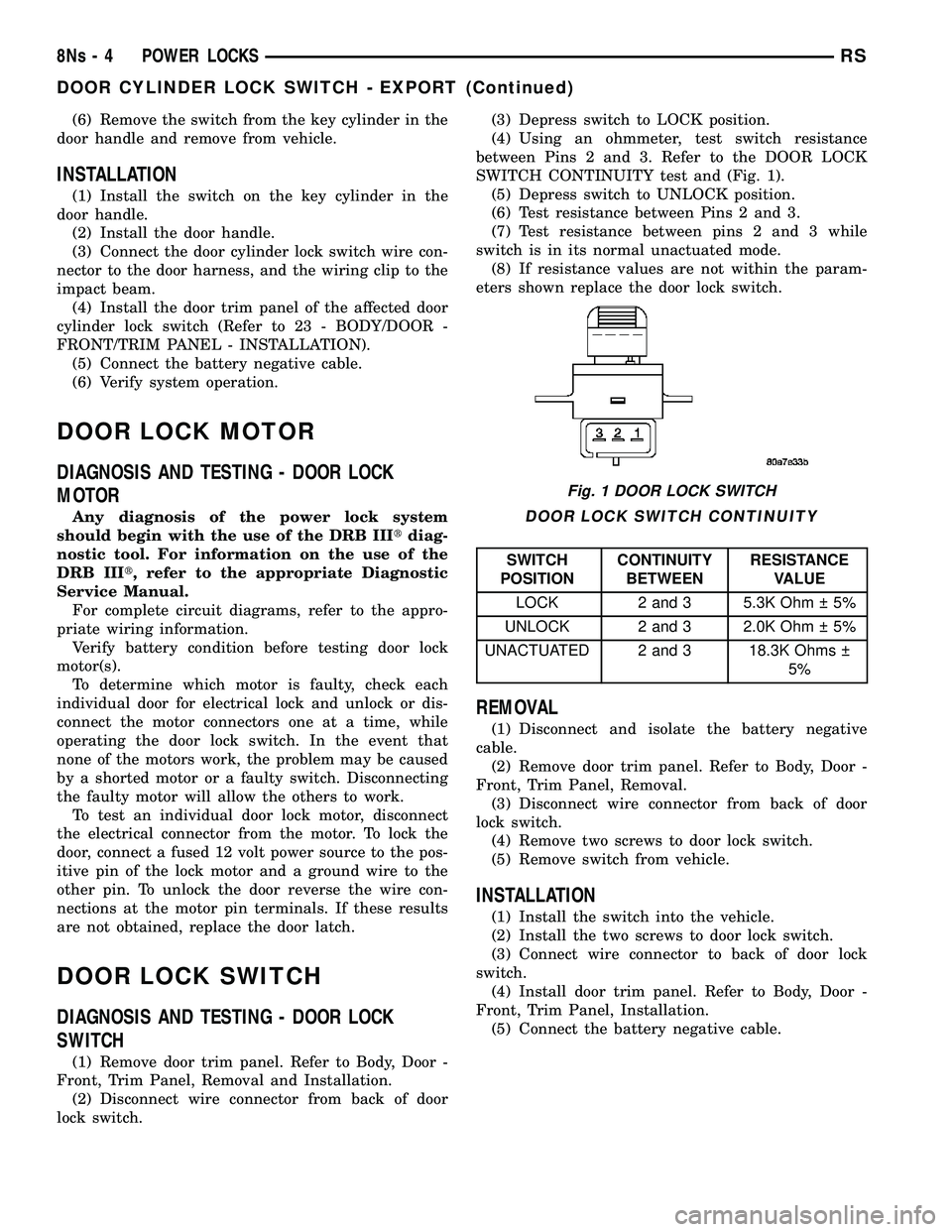
DOOR LOCK SWITCH
DIAGNOSIS AND TESTING - DOOR LOCK
SWITCH
(1) Remove door trim panel. Refer to Body, Door -
Front, Trim Panel, Removal and Installation. (2) Disconnect wire connector from back of door
lock switch. (3) Depress switch to LOCK position.
(4) Using an ohmmeter, test switch resistance
between Pins 2 and 3. Refer to the DOOR LOCK
SWITCH CONTINUITY test and (Fig. 1). (5) Depress switch to UNLOCK position.
(6) Test resistance between Pins 2 and 3.
(7) Test resistance between pins 2 and 3 while
switch is in its normal unactuated mode. (8) If resistance values are not within the param-
eters shown replace the door lock switch.
DOOR LOCK SWITCH CONTINUITY
SWITCH
POSITION CONTINUITY
BETWEEN RESISTANCE
VALUE
LOCK 2 and 3 5.3K Ohm 5%
UNLOCK 2 and 3 2.0K Ohm 5%
UNACTUATED 2 and 3 18.3K Ohms 5%
REMOVAL
(1) Disconnect and isolate the battery negative
cable. (2) Remove door trim panel. Refer to Body, Door -
Front, Trim Panel, Removal. (3) Disconnect wire connector from back of door
lock switch. (4) Remove two screws to door lock switch.
(5) Remove switch from vehicle.
INSTALLATION
(1) Install the switch into the vehicle.
(2) Install the two screws to door lock switch.
(3) Connect wire connector to back of door lock
switch. (4) Install door trim panel. Refer to Body, Door -
Front, Trim Panel, Installation. (5) Connect the battery negative cable.
Fig. 1 DOOR LOCK SWITCH
8Ns - 4 POWER LOCKSRS
DOOR CYLINDER LOCK SWITCH - EXPORT (Continued)
Page 644 of 2585
POWER SEAT SYSTEM
TABLE OF CONTENTS
page page
POWER SEAT SYSTEM DESCRIPTION DESCRIPTION ........................7
DESCRIPTION - MEMORY SYSTEM ........8
OPERATION OPERATION - POWER SEAT SYSTEM ......9
OPERATION - MEMORY SYSTEM ..........9
DIAGNOSIS AND TESTING DIAGNOSIS AND TESTING - POWER SEATSYSTEM .............................9
DIAGNOSIS AND TESTING - MEMORY SYSTEM ............................10
DRIVER SEAT SWITCH DESCRIPTION .........................10
OPERATION ...........................11
DIAGNOSIS AND TESTING - DRIVER SEAT SWITCH .............................11
REMOVAL .............................12
INSTALLATION .........................12
MEMORY SET SWITCH DESCRIPTION .........................12
OPERATION ...........................13
DIAGNOSIS AND TESTING - MEMORY SWITCH ............................13 REMOVAL
.............................13
INSTALLATION .........................13
PASSENGER SEAT SWITCH DESCRIPTION .........................13
OPERATION ...........................13
DIAGNOSIS AND TESTING - PASSENGER SEAT SWITCH ........................14
REMOVAL .............................14
INSTALLATION .........................15
DRIVER POWER SEAT TRACK DESCRIPTION .........................15
OPERATION ...........................15
DIAGNOSIS AND TESTING - DRIVER POWER SEAT TRACK .........................15
REMOVAL .............................16
INSTALLATION .........................16
PASSENGER POWER SEAT TRACK DESCRIPTION .........................16
OPERATION ...........................17
DIAGNOSIS AND TESTING - POWER SEAT TRACK .............................17
REMOVAL .............................18
INSTALLATION .........................18
POWER SEAT SYSTEM
DESCRIPTION
DESCRIPTION
The power seat system option allows the driver
and front seat passenger to electrically adjust their
seating positions for optimum control and comfort
using the power seat switches located on the out-
board seat cushion side shield of each front seat. The
driver side power front seat can be adjusted in eight
different directions: up, down, front up, front down,
rear up, rear down, forward, rearward and recliner
forward and rearward. The passenger side power
front seat can be adjusted in four different directions:
forward, rearward and recliner forward and rear-
ward. The power seat system receives battery current
through a 40 amp fuse in the Intelligent Power Mod-
ule and a 30 amp circuit breaker under the seat so
that the power seats remain operational, regardless
of the ignition switch position. WARNING: SOME VEHICLES ARE EQUIPPED WITH
SEATBACK MOUNTED AIRBAGS (Fig. 1). BEFORE
ATTEMPTING TO DIAGNOSE OR SERVICE ANY
SEAT OR POWER SEAT SYSTEM COMPONENT
YOU MUST FIRST DISCONNECT AND ISOLATE THE
BATTERY NEGATIVE CABLE. THEN WAIT TWO MIN-
UTES FOR THE SYSTEM CAPACITOR TO DIS-
CHARGE BEFORE FURTHER SYSTEM SERVICE.
THIS IS THE ONLY SURE WAY TO DISABLE THE
AIRBAG SYSTEM. FAILURE TO DO SO COULD
RESULT IN ACCIDENTAL AIRBAG DEPLOYMENT
AND POSSIBLE PERSONAL INJURY.
A eight-way driver side power seat is standard on
highline models and optional on others. This option
includes a six-way adjustable seat cushion track and
a two-way power seat back. The eight-way driver side power seat is also avail-
able with the heated seat and/or memory seat system
that automatically positions the power seat for two
different drivers. Refer to Heated Seatsfor more
information on the heated seat option. Refer to
Description - Memory System in this section for
more information on the memory seat system.
RS POWER SEAT SYSTEM8Ns-7
Page 646 of 2585
Refer toHeated Seat System for more informa-
tion on the heated seat system. Refer to Remote
Keyless Entry System in Power Lock Systems for
more information on the RKE system. Refer to Wiring Diagrams for complete circuit
diagrams. Following are descriptions, theory of oper-
ation, diagnosis/testing procedures and removal/in-
stallation procedures of the major components in the
memory and power seat systems.
OPERATION
OPERATION - POWER SEAT SYSTEM
The power seat system receives battery current
through fuse #22 in the Intelligent Power Module
and a circuit breaker under the front seats, regard-
less of the ignition switch position. When a power seat switch control knob or knobs
are actuated, a battery feed and a ground path are
applied through the switch contacts to the appropri-
ate power seat track adjuster motor. The selected
adjuster motor operates to move the seat track
through its drive unit in the selected direction until
the switch is released, or until the travel limit of the
seat track is reached. When the switch is moved in
the opposite direction, the battery feed and ground
path to the motor are reversed through the switch
contacts. This causes the adjuster motor to run in the
opposite direction. No power seat switch should be held applied in any
direction after the seat track has reached its travel
limit. The power seat track each contain a self-reset-
ting circuit breaker to protect them from overload.
However, consecutive or frequent resetting of the cir-
cuit breaker must not be allowed to continue, or the
motor may be damaged. Refer to the owner's manual
in the vehicle glove box for more information on the
features, use and operation of the power seat system.
OPERATION - MEMORY SYSTEM
The Memory Seat Mirror Module (MSMM) receives
battery current through fuse #22 in the Intelligent
Power Module and the power seat system circuit
breaker, located under the driver side front seat near
the rear edge of the seat cushion pan. The memory
system does not operate with the Ignition-Off Draw
(IOD) fuse removed. The MSMM will drive a maxi-
mum of 2 motors at a time in a given direction. If
conflicting directions are requested, the priority for
response will be approximately as follows: ² Seat Track Rearward or Forward
² Seat Front Down or Up
² Seat Rear Down or Up
² Recliner Rearward or Forward The inputs from these switches to the MSMM is a
current limited battery source fed by the MSMM.
This protects the MSMM printed circuit board traces
from acting as fuses. All of these switch contact
inputs to the MSMM are normally closed to ground,
except when actuated. See the owner's manual in the vehicle glove box for
more information on the features, use and operation
of the memory system. For diagnosis of the MSMM,
the PCI data bus, or the other electronic modules on
the PCI data bus that provide inputs and outputs for
the memory system, the use of a DRBIII tscan tool
and the proper Diagnostic Procedures manual are
recommended.
ELECTRONIC VEHICLE INFORMATION CENTER
The Electronic Vehicle Information Center (EVIC)
serves as the user interface for the memory system.
It displays memory system status messages and pro-
vides the user with the means for enabling and dis-
abling the many customer programmable features
available on the vehicle, including those for the mem-
ory system. See the owner's manual in the vehicle glove box for
more information on the features, use and operation
of the EVIC. Refer to Electronic Vehicle Informa-
tion Center in Overhead Console Systems for more
information on the EVIC.
DIAGNOSIS AND TESTING
DIAGNOSIS AND TESTING - POWER SEAT
SYSTEM
Following are tests that will help to diagnose the
hard wired components and circuits of the power seat
system. However, if the vehicle is also equipped with
the optional memory system, these tests may not
prove conclusive in the diagnosis of the driver side
power seat. In order to obtain conclusive testing of
the driver side power seat with the memory system
option, the Programmable Communications Interface
(PCI) data bus network and all of the electronic mod-
ules that provide inputs to, or receive outputs from
the memory system components must be checked. The most reliable, efficient, and accurate means to
diagnose the driver side power seat with the memory
system option requires the use of a DRBIII tscan tool
and the proper Diagnostic Procedures manual. The
DRBIII tscan tool can provide confirmation that the
PCI data bus is functional, that all of the electronic
modules are sending and receiving the proper mes-
sages on the PCI data bus, and that the memory sys-
tem is receiving the proper hard wired inputs and
relaying the proper hard wired outputs to perform its
driver side power seat functions.
RS POWER SEAT SYSTEM8Ns-9
POWER SEAT SYSTEM (Continued)
Page 653 of 2585
and test again to be certain that the adjuster is not
at its travel limit. If the power seat track adjuster
still fails to operate in only one direction, refer to
Diagnosis and Testing Power Seat Switchin this
section. If the power seat track adjuster fails to oper-
ate in more than one direction, perform the following
tests. For complete circuit diagrams, refer to Wiring
Diagrams .
TESTING POWER SEAT TRACK MOTORS
(1) Check the power seat circuit breaker under the
seat. If OK, go to Step 2. If not OK, replace the
faulty power seat circuit breaker. (2) Check for battery voltage at the power seat cir-
cuit breaker under the seat. If OK, go to Step 3. If
not OK, repair the open fused B(+) circuit to the fuse
in the Intelligent Power Module as required. (3) Remove the outboard seat cushion side shield
from the seat. Disconnect the seat wire harness con-
nector from the power seat switch connector recepta-
cle. Check for battery voltage at the fused B(+)
circuit cavity of the power seat wire harness connec-
tor for the power seat switch. If OK, go to Step 4. If
not OK, repair the open fused B(+) circuit to the
power seat circuit breaker under the seat as
required. (4) Check for continuity between the ground cir-
cuit cavity of the power seat wire harness connector
for the power seat switch and a good ground. There
should be continuity. If OK, go to Step 5. If not OK,
repair the open ground circuit to ground as required. (5) Test the power seat switch. Refer to Diagnosis
and Testing Power Seat Switch in this section. If
the switch tests OK, test the circuits of the power
seat wire harness between the inoperative power seat
track adjuster motor and the power seat switch for
shorts or opens. If the circuits check OK, replace the
faulty power seat track unit. If the circuits are not
OK, repair the power seat wire harness as required.
REMOVAL
WARNING: SOME VEHICLES ARE EQUIPPED WITH
SEATBACK MOUNTED AIRBAGS. BEFORE
ATTEMPTING TO DIAGNOSE OR SERVICE ANY
SEAT OR POWER SEAT SYSTEM COMPONENT
YOU MUST FIRST DISCONNECT AND ISOLATE THE
BATTERY NEGATIVE CABLE. THEN WAIT TWO MIN-
UTES FOR THE SYSTEM CAPACITOR TO DIS-
CHARGE BEFORE FURTHER SYSTEM SERVICE.
THIS IS THE ONLY SURE WAY TO DISABLE THE
AIRBAG SYSTEM. FAILURE TO DO SO COULD
RESULT IN ACCIDENTAL AIRBAG DEPLOYMENT
AND POSSIBLE PERSONAL INJURY. (1) Remove the appropriate seat from the vehicle
and place it on a clean work surface(Refer to 23 -
BODY/SEATS/SEAT - REMOVAL). (2) If the vehicle is so equipped, remove the Mem-
ory Seat/Mirror Module (MSMM) retaining screws. (3) If the vehicle is so equipped, disconnect the
MSMM electrical connectors and remove the MSMM
from the power seat track. (4) Remove the rear fabric blocker trim panel from
the rear of the front seat. (5) Remove the seat side cover and power seat
switch as an assembly (Refer to 23 - BODY/SEATS/
SEAT CUSHION SIDE COVERS - REMOVAL). (6) Disconnect all electrical connectors connecting
the power seat track to the seat assembly. (7) Pull the seat back trim cover up slightly to
access and remove the two seat back frame mounting
bolts and also remove two seat back recliner bolts. (8) Remove four seat track mounting bolts from
the seat cushion pan. (9) Remove the power seat track from the seat.
INSTALLATION
(1) Position the seat cushion on the seat track.
(2) Install the four seat track retaining bolts in the
seat cushion pan. Torque the bolts to 28.5 N´m. (3) Position the seat back and install the two seat
back frame mounting bolts and the two seat back
recliner bolts. Torque the bolts to 55 N´m. (4) Route and connect the electrical connectors
between the power seat track and the seat assembly. (5) Install the seat side cover and power seat
switch as an assembly (Refer to 23 - BODY/SEATS/
SEAT CUSHION SIDE COVERS - INSTALLATION). (6) Install the rear fabric blocker trim panel on the
rear of the front seat. (7) If the vehicle is so equipped, position the Mem-
ory Seat/Mirror Module (MSMM) and connect the
MSMM electrical connectors. (8) Install the MSMM retaining screws.
(9) Install the seat assembly in the vehicle (Refer
to 23 - BODY/SEATS/SEAT - INSTALLATION).
PASSENGER POWER SEAT
TRACK
DESCRIPTION
The four-way passenger side power seat option
includes a electrically operated power seat track unit
located under the passenger side front seat. The
power seat circuit breaker is mounted on the rear of
the power seat track, just behind the seat rear trim
panel. The lower half of the power seat track is
secured to the floor panel via four studs and nuts
that must be accessed from the underside of the vehi-
8Ns - 16 POWER SEAT SYSTEMRS
DRIVER POWER SEAT TRACK (Continued)