window CHRYSLER VOYAGER 2004 Workshop Manual
[x] Cancel search | Manufacturer: CHRYSLER, Model Year: 2004, Model line: VOYAGER, Model: CHRYSLER VOYAGER 2004Pages: 2585, PDF Size: 62.54 MB
Page 1235 of 2585

CONNECTOR NAME/NUMBER COLOR LOCATION FIG.
Driver Airbag Squib1 BN Steering Column N/S
Driver Airbag Squib2 BK Steering Column N/S
Driver Blend Door Actuator GY On HVAC N/S
Driver Door Courtesy Lamp GY At Lamp 43
Driver Door Lock Switch BK At Switch 43
Driver Heated Seat Back LTGN At Seat N/S
Driver Heated Seat Cushion BK At Seat N/S
Driver Heated Seat Module C1 GY Driver Heated Seat N/S
Driver Heated Seat Module C2 GY Driver Heated Seat Back N/S
Driver Heated Seat Module C3 GN At Seat N/S
Driver Power Seat Front Riser
MotorRD At Seat N/S
Driver Power Seat Front Riser
Position SensorBK At Seat N/S
Driver Power Seat Horizontal
MotorBK At Seat N/S
Driver Power Seat Horizontal
Position SensorBK At Seat N/S
Driver Power Seat Rear Riser
MotorRD At Seat N/S
Driver Power Seat Rear Riser
Position SensorBK At Seat N/S
Driver Power Seat Recliner Motor GN At Seat N/S
Driver Power Seat Recliner
Position SensorBK At Seat N/S
Driver Power Seat Switch GN At Switch N/S
Driver Power Window Motor RD At Motor 43
Driver Power Window Switch
(LHD Low Line)GN At Switch 43
Driver Power Window Switch
(LHD Except Low Line)LTGY At Switch N/S
Driver Power Window Switch
(RHD)NAT At Switch N/S
Driver Seat Belt Switch WT At Switch on Seat Harness N/S
Driver Seat Belt Tensioner yl On Seat Harness N/S
DVD Screen BK Headliner 50
DVD/CD Changer C1 Below Radio N/S
DVD/CD Changer C2 Below Radio N/S
DVD/CD Changer C3 BK At Radio 20
EGR Solenoid (Diesel) LTGY Above Transmission
Right Side of Engine15
EGR Solenoid (3.3L/3.8L) GY Above A/C Compressor Right Side
of Engine18
Engine Control Module C1
(Diesel)BK Right Side of Engine N/S
8W - 91 - 4 8W-91 CONNECTOR/GROUND/SPLICE LOCATIONRS
CONNECTOR/GROUND/SPLICE LOCATION (Continued)
Page 1240 of 2585

CONNECTOR NAME/NUMBER COLOR LOCATION FIG.
Passenger Heated Seat Module
C2GY At Heated Seat Back N/S
Passenger Heated Seat Module
C3GN At Heated Seat N/S
Passenger Power Seat Front
Riser MotorRD Under Seat N/S
Passenger Power Seat Horizontal
MotorBK Under Seat N/S
Passenger Power Seat Rear
Riser MotorRD Under Seat N/S
Passenger Power Seat Recliner
MotorGN Under Seat N/S
Passenger Power Seat Switch GN At Switch N/S
Passenger Power Window Motor RD At Motor 44
Passenger Power Window Switch BK At Switch 44
Passenger Seat Belt Switch On Seat Harness N/S
Passenger Seat Belt Tensioner On Seat Harness N/S
Power Folding Mirror Switch
(Export)BK Near Steering Column 31
Power Liftgate Module C1 BK Left Quarter 46, 47
Power Liftgate Module C2 Left Quarter 46, 47
Power Liftgate Motor BK Left Quarter 47
Power Mirror Switch BK Rear of Switch 30
Power Outlet (Except Lowline) BK Instrument Panel 20, 23, 25
Power Seat Circuit Breaker GY Under Seat N/S
Powertrain Control Module C1 BK Left Front Engine Compartment 11
Powertrain Control Module C2 BK Left Front Engine Compartment 11
Powertrain Control Module C3 BK Left Front Engine Compartment 11
Powertrain Control Module C4
(EATX)DKGN Left Front Engine Compartment 11
Power Window Circuit Breaker GY Left Side Kick Panel 41 42
Power Window Switch (LHD
Lowline)BK Driver Door 43
Radiator Fan No.1 (Gas) BK Left Side At Motor 1
Radiator Fan No.1 (Diesel) GY Left Side At Motor 1
Radiator Fan No.2 (Gas) BK Right Side At Motor 1, 2
Radiator Fan No.2 (Diesel) GY Right Side At Motor 1, 2
Radiator Fan Relay (Gas) Top of Left Front Frame Rail 1
Radiator Fan Relay No. 1
(Diesel)BL Left Front Engine Compartment 2
Radiator Fan Relay No. 2
(Diesel)BL Left Front Engine Compartment 2
Radiator Fan Relay No. 3
(Diesel)BL Left Front Engine Compartment 2
Radio C1 Rear of Radio 20
RS8W-91 CONNECTOR/GROUND/SPLICE LOCATION8W-91-9
CONNECTOR/GROUND/SPLICE LOCATION (Continued)
Page 1246 of 2585

SPLICE NUMBER LOCATION FIG.
S212 In Steering Column Wiring Assembly N/S
S222 Near T/O for C204 N/S
S223 Near T/O for Multi-Function Switch 20
S224 Near T/O for Siren N/S
S302 In Floor Pan Track Wiring 37
S303 In T/O to Data Link Connector 37, 41, 42
S304 In Floor Pan Track Wiring 38
S305 Near T/O for Memory Seat/Mirror Module - C2 N/S
S306 In Floor Pan Track Wiring 34, 38
S307 Near T/O for Memory Power Seat Switch N/S
S309 In Floor Pan Track Wiring N/S
S310 Near T/O for C301 35, 36, 37
S311 In Floor Pan Track Wiring N/S
S312 Near T/O for C320 N/S
S313 Near T/O for Power Liftgate Module 47
S314 In Floor Pan Track Wiring 34
S315 In Floor Pan Track Wiring 34
S316 In Floor Pan Track Wiring 37
S317 Near T/O for C101 35, 36
S318 Near T/O for Power Seat Circuit Breaker 34
S319 In Floor Pan Track Wiring 38
S321 Ner T/O for C301 35, 36, 37
S322 Near T/O for C301 35, 37
S323 In Floor Pan Track Wiring 34
S324 In Floor Pan Track Wiring 34
S325 In Floor Pan Track Wiring 34
S326 Near T/O for C101 35, 36
S327 Near Left Side Impact Airbag Module 37, 40
S329 Near T/O to Left Rear Pillar Speaker 47
S330 Near T/O for Power Liftgate Module 47
S331 Near T/O for Power Liftgate Motor 47
S332 In Floor Pan Track Wiring N/S
S334 Near T/O to G301 34
S335 Near T/O for Left Rear Reading Lamp N/S
S336 Near T/O for Left Rear Reading Lamp N/S
S337 Near T/O for Right Mid Reading Lamp N/S
S338 Near T/O for Right Visor/Vanity Lamp N/S
S339 Near T/O for C312 N/S
S340 Near T/O for Passenger Power Window Switch N/S
S342 (LHD) Near T/O for Passenger Power Window Motor 44
S343 (LHD) Near T/O for Driver Power Window Motor 43
S344 In T/O to Right Sliding Door Control Module C2 45, 46
RS8W-91 CONNECTOR/GROUND/SPLICE LOCATION8W-91-15
CONNECTOR/GROUND/SPLICE LOCATION (Continued)
Page 1247 of 2585
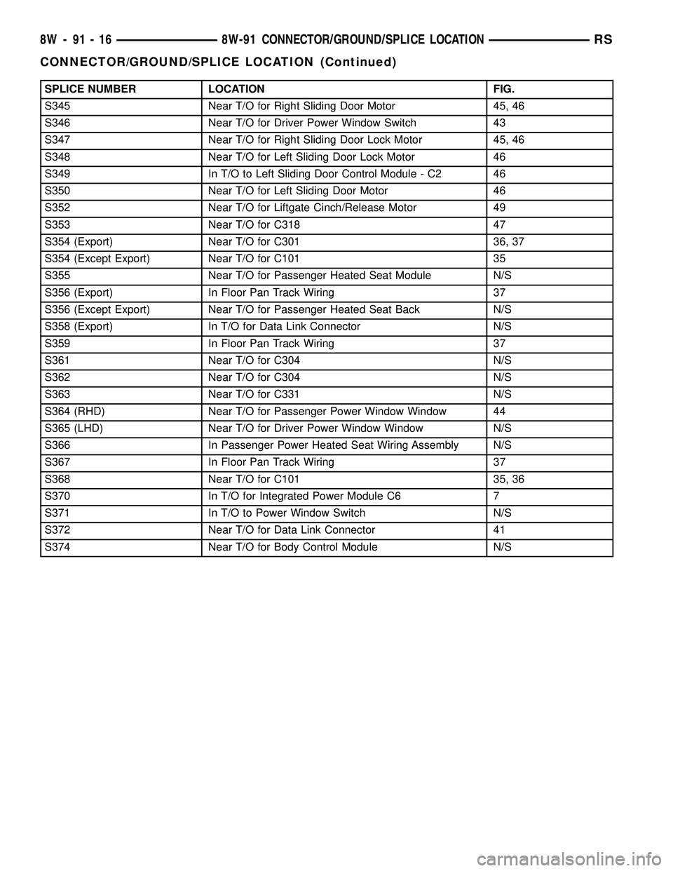
SPLICE NUMBER LOCATION FIG.
S345 Near T/O for Right Sliding Door Motor 45, 46
S346 Near T/O for Driver Power Window Switch 43
S347 Near T/O for Right Sliding Door Lock Motor 45, 46
S348 Near T/O for Left Sliding Door Lock Motor 46
S349 In T/O to Left Sliding Door Control Module - C2 46
S350 Near T/O for Left Sliding Door Motor 46
S352 Near T/O for Liftgate Cinch/Release Motor 49
S353 Near T/O for C318 47
S354 (Export) Near T/O for C301 36, 37
S354 (Except Export) Near T/O for C101 35
S355 Near T/O for Passenger Heated Seat Module N/S
S356 (Export) In Floor Pan Track Wiring 37
S356 (Except Export) Near T/O for Passenger Heated Seat Back N/S
S358 (Export) In T/O for Data Link Connector N/S
S359 In Floor Pan Track Wiring 37
S361 Near T/O for C304 N/S
S362 Near T/O for C304 N/S
S363 Near T/O for C331 N/S
S364 (RHD) Near T/O for Passenger Power Window Window 44
S365 (LHD) Near T/O for Driver Power Window Window N/S
S366 In Passenger Power Heated Seat Wiring Assembly N/S
S367 In Floor Pan Track Wiring 37
S368 Near T/O for C101 35, 36
S370 In T/O for Integrated Power Module C6 7
S371 In T/O to Power Window Switch N/S
S372 Near T/O for Data Link Connector 41
S374 Near T/O for Body Control Module N/S
8W - 91 - 16 8W-91 CONNECTOR/GROUND/SPLICE LOCATIONRS
CONNECTOR/GROUND/SPLICE LOCATION (Continued)
Page 1364 of 2585

(8) Check if the spring tang is within the tolerance
window (Fig. 125). If the spring tang is within the
tolerance window, the installation process is complete
and nothing further is required. If the spring tang is
not within the tolerance window, repeat Steps 5
through 7.
(9) Install engine mount bracket to engine (Fig.
115).
(10) Install timing belt front covers and bolts
(Refer to 9 - ENGINE/VALVE TIMING/TIMING
BELT COVER(S) - INSTALLATION).
(11) Install air conditioning/generator belt ten-
sioner and pulley (Refer to 7 - COOLING/ACCES-
SORY DRIVE/BELT TENSIONERS -
INSTALLATION).(12) Install right engine mount (Refer to 9 -
ENGINE/ENGINE MOUNTING/RIGHT MOUNT -
INSTALLATION).
(13) Install crankshaft vibration damper (Refer to
9 - ENGINE/ENGINE BLOCK/VIBRATION
DAMPER - INSTALLATION).
(14) Install accessory drive belts (Refer to 7 -
COOLING/ACCESSORY DRIVE/DRIVE BELTS -
INSTALLATION).
(15) Install drive belt splash shield.
(16) Install right front wheel.
(17) Connect make-up air hose to cylinder head
cover.
(18) Install air cleaner housing, upper cover, and
clean air tube.
Fig. 124 Crankshaft and Camshaft Timing
1 - CAMSHAFT TIMING MARKS
2 - CRANKSHAFT TDC MARKS
3 - TRAILING EDGE OF SPROCKET TOOTH
Fig. 125 Timing Belt Tension Verification
1 - SPRING TANG
2 - TOLERANCE WINDOW
RSENGINE 2.4L9-67
TIMING BELT AND SPROCKET(S) (Continued)
Page 1521 of 2585

QUICK CONNECT FITTING
STANDARD PROCEDURE - QUICK-CONNECT
FITTINGS
REMOVAL
When disconnecting a quick-connect fitting, the
retainer will remain on the fuel tube nipple.
WARNING: RELEASE FUEL SYSTEM PRESSURE
BEFORE DISCONNECTING A QUICK-CONNECT FIT-
TINGS. REFER TO THE FUEL PRESSURE RELEASE
PROCEDURE. THIS MAY RESULT IN PERSONAL
INJURY OR DEATH.
(1) Perform Fuel Pressure Release Procedure.
Refer to the Fuel Pressure Release Procedure in this
section.
(2) Disconnect negative cable from battery or aux-
iliary jumper terminal.
(3) Squeeze retainer tabs together and pull fuel
tube/quick-connect fitting assembly off of fuel tube
nipple. The retainer will remain on fuel tube.
INSTALLATION
CAUTION: Make sure that the o-ring in installed in
fitting. Never install a quick-connect fitting without
the retainer being either on the fuel tube or already
in the quick-connect fitting. In either case, ensure
the retainer locks securely into the quick-connect
fitting by firmly push-pulling-push on fuel tube and
fitting to ensure it is secured.
(1) Using a clean lint free cloth, clean the fuel tube
nipple and retainer.
(2) Prior to connecting the fitting to the fuel tube,
coat the fuel tube nipple with clean engine oil.
(3) Push the quick-connect fitting over the fuel
tube until theretainer seats and a click is heard.
(4) The plastic quick-connect fitting has windows
in the sides of the casing. When the fitting com-
pletely attaches to the fuel tube, the retainer locking
ears and the fuel tube shoulder are visible in the
windows. If they are not visible, the retainer was not
properly installed (Fig. 22).Do not rely upon the
audible click to confirm a secure connection.
(5) Connect negative cable to battery or auxiliary
jumper terminal.
CAUTION: When using the ASD Fuel System Test,
the Auto Shutdown (ASD) Relay remains energized
for several minutes, until the test is stopped, or
until the ignition switch is turned to the Off posi-
tion.(6) Use the DRB IIItscan tool ASD Fuel System
Test to pressurize the fuel system. Check for leaks.
TWO-TAB TYPE FITTING
This type of fitting is equipped with tabs located on
both sides of the fitting (Fig. 23). These tabs are sup-
plied for disconnecting the quick-connect fitting from
component being serviced.
CAUTION: The interior components (O-rings, spac-
ers) of this type of quick-connect fitting are not ser-
viced separately, but new plastic retainers are
available. Do not attempt to repair damaged fittings
or fuel lines/tubes. If repair is necessary, replace
the complete fuel tube assembly.
Fig. 22 Plastic Quick-Connect Fitting/Fuel Tube
Connection
1 - WINDOW
2-TAB(2)
3 - EAR
4 - SHOULDER (ON TUBE)
Fig. 23 Typical Two-Tab Type Quick-Connect Fitting
1 - TAB(S)
2 - QUICK-CONNECT FITTING
14 - 14 FUEL DELIVERYRS
Page 2113 of 2585
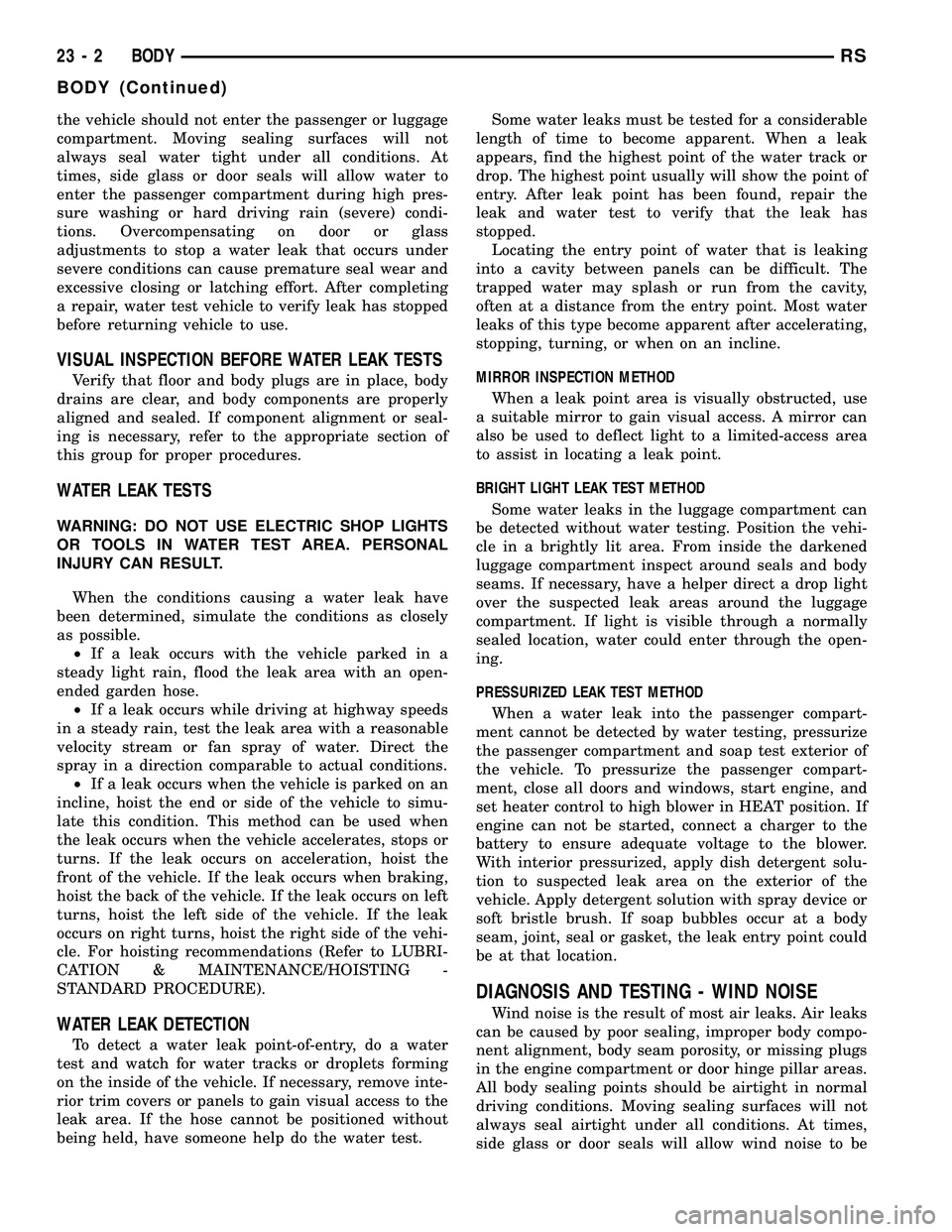
the vehicle should not enter the passenger or luggage
compartment. Moving sealing surfaces will not
always seal water tight under all conditions. At
times, side glass or door seals will allow water to
enter the passenger compartment during high pres-
sure washing or hard driving rain (severe) condi-
tions. Overcompensating on door or glass
adjustments to stop a water leak that occurs under
severe conditions can cause premature seal wear and
excessive closing or latching effort. After completing
a repair, water test vehicle to verify leak has stopped
before returning vehicle to use.
VISUAL INSPECTION BEFORE WATER LEAK TESTS
Verify that floor and body plugs are in place, body
drains are clear, and body components are properly
aligned and sealed. If component alignment or seal-
ing is necessary, refer to the appropriate section of
this group for proper procedures.
WATER LEAK TESTS
WARNING: DO NOT USE ELECTRIC SHOP LIGHTS
OR TOOLS IN WATER TEST AREA. PERSONAL
INJURY CAN RESULT.
When the conditions causing a water leak have
been determined, simulate the conditions as closely
as possible.
²If a leak occurs with the vehicle parked in a
steady light rain, flood the leak area with an open-
ended garden hose.
²If a leak occurs while driving at highway speeds
in a steady rain, test the leak area with a reasonable
velocity stream or fan spray of water. Direct the
spray in a direction comparable to actual conditions.
²If a leak occurs when the vehicle is parked on an
incline, hoist the end or side of the vehicle to simu-
late this condition. This method can be used when
the leak occurs when the vehicle accelerates, stops or
turns. If the leak occurs on acceleration, hoist the
front of the vehicle. If the leak occurs when braking,
hoist the back of the vehicle. If the leak occurs on left
turns, hoist the left side of the vehicle. If the leak
occurs on right turns, hoist the right side of the vehi-
cle. For hoisting recommendations (Refer to LUBRI-
CATION & MAINTENANCE/HOISTING -
STANDARD PROCEDURE).
WATER LEAK DETECTION
To detect a water leak point-of-entry, do a water
test and watch for water tracks or droplets forming
on the inside of the vehicle. If necessary, remove inte-
rior trim covers or panels to gain visual access to the
leak area. If the hose cannot be positioned without
being held, have someone help do the water test.Some water leaks must be tested for a considerable
length of time to become apparent. When a leak
appears, find the highest point of the water track or
drop. The highest point usually will show the point of
entry. After leak point has been found, repair the
leak and water test to verify that the leak has
stopped.
Locating the entry point of water that is leaking
into a cavity between panels can be difficult. The
trapped water may splash or run from the cavity,
often at a distance from the entry point. Most water
leaks of this type become apparent after accelerating,
stopping, turning, or when on an incline.
MIRROR INSPECTION METHOD
When a leak point area is visually obstructed, use
a suitable mirror to gain visual access. A mirror can
also be used to deflect light to a limited-access area
to assist in locating a leak point.
BRIGHT LIGHT LEAK TEST METHOD
Some water leaks in the luggage compartment can
be detected without water testing. Position the vehi-
cle in a brightly lit area. From inside the darkened
luggage compartment inspect around seals and body
seams. If necessary, have a helper direct a drop light
over the suspected leak areas around the luggage
compartment. If light is visible through a normally
sealed location, water could enter through the open-
ing.
PRESSURIZED LEAK TEST METHOD
When a water leak into the passenger compart-
ment cannot be detected by water testing, pressurize
the passenger compartment and soap test exterior of
the vehicle. To pressurize the passenger compart-
ment, close all doors and windows, start engine, and
set heater control to high blower in HEAT position. If
engine can not be started, connect a charger to the
battery to ensure adequate voltage to the blower.
With interior pressurized, apply dish detergent solu-
tion to suspected leak area on the exterior of the
vehicle. Apply detergent solution with spray device or
soft bristle brush. If soap bubbles occur at a body
seam, joint, seal or gasket, the leak entry point could
be at that location.
DIAGNOSIS AND TESTING - WIND NOISE
Wind noise is the result of most air leaks. Air leaks
can be caused by poor sealing, improper body compo-
nent alignment, body seam porosity, or missing plugs
in the engine compartment or door hinge pillar areas.
All body sealing points should be airtight in normal
driving conditions. Moving sealing surfaces will not
always seal airtight under all conditions. At times,
side glass or door seals will allow wind noise to be
23 - 2 BODYRS
BODY (Continued)
Page 2116 of 2585
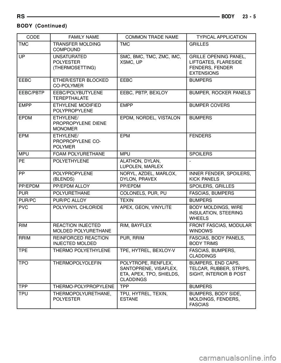
CODE FAMILY NAME COMMON TRADE NAME TYPICAL APPLICATION
TMC TRANSFER MOLDING
COMPOUNDTMC GRILLES
UP UNSATURATED
POLYESTER
(THERMOSETTING)SMC, BMC, TMC, ZMC, IMC,
XSMC, UPGRILLE OPENING PANEL,
LIFTGATES, FLARESIDE
FENDERS, FENDER
EXTENSIONS
EEBC ETHER/ESTER BLOCKED
CO-POLYMEREEBC BUMPERS
EEBC/PBTP EEBC/POLYBUTYLENE
TEREPTHALATEEEBC, PBTP, BEXLOY BUMPER, ROCKER PANELS
EMPP ETHYLENE MODIFIED
POLYPROPYLENEEMPP BUMPER COVERS
EPDM ETHYLENE/
PROPROPYLENE DIENE
MONOMEREPDM, NORDEL, VISTALON BUMPERS
EPM ETHYLENE/
PROPROPYLENE CO-
POLYMEREPM FENDERS
MPU FOAM POLYURETHANE MPU SPOILERS
PE POLYETHYLENE ALATHON, DYLAN,
LUPOLEN, MARLEX-
PP POLYPROPYLENE
(BLENDS)NORYL, AZDEL, MARLOX,
DYLON, PRAVEXINNER FENDER, SPOILERS,
KICK PANELS
PP/EPDM PP/EPDM ALLOY PP/EPDM SPOILERS, GRILLES
PUR POLYURETHANE COLONELS, PUR, PU FASCIAS, BUMPERS
PUR/PC PUR/PC ALLOY TEXIN BUMPERS
PVC POLYVINYL CHLORIDE APEX, GEON, VINYLITE BODY MOLDINGS, WIRE
INSULATION, STEERING
WHEELS
RIM REACTION INJECTED
MOLDED POLYURETHANERIM, BAYFLEX FRONT FASCIAS, MODULAR
WINDOWS
RRIM REINFORCED REACTION
INJECTED MOLDEDPUR, RRIM FASCIAS, BODY PANELS,
BODY TRIMS
TPE THERMO POLYETHYLENE TPE, HYTREL, BEXLOY-V FASCIAS, BUMPERS,
CLADDINGS
TPO THERMOPOLYOLEFIN POLYTROPE, RENFLEX,
SANTOPRENE, VISAFLEX,
ETA, APEX, TPO, SHIELDS,
CLADDINGSBUMPERS, END CAPS,
TELCAR, RUBBER, STRIPS,
SIGHT, INTERIOR B POST
TPP THERMO-POLYPROPYLENE TPP BUMPERS
TPU THERMOPOLYURETHANE,
POLYESTERTPU, HYTREL, TEXIN,
ESTANEBUMPERS, BODY SIDE,
MOLDINGS, FENDERS,
FASCIAS
RSBODY23-5
BODY (Continued)
Page 2125 of 2585
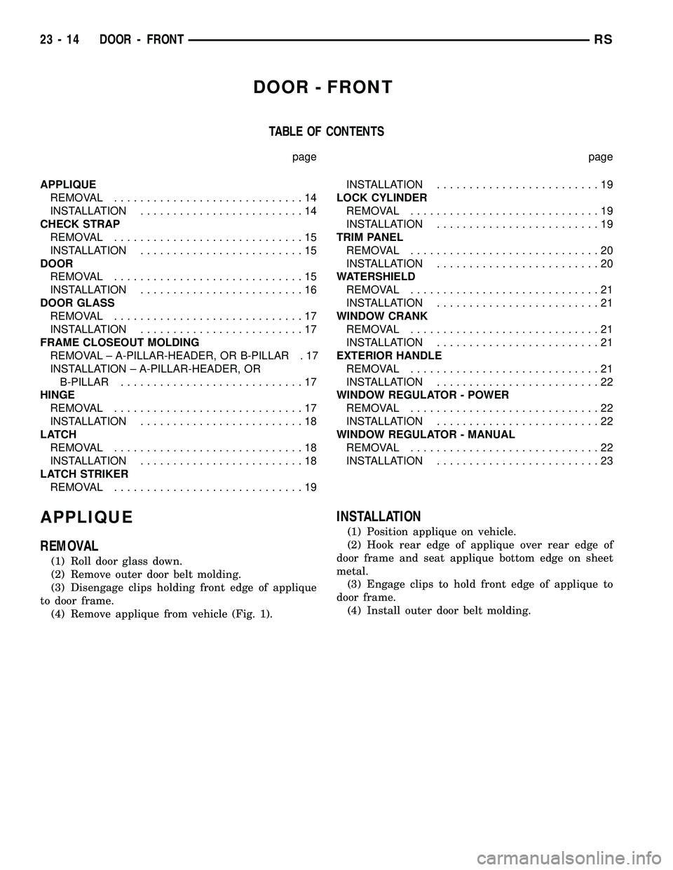
DOOR - FRONT
TABLE OF CONTENTS
page page
APPLIQUE
REMOVAL.............................14
INSTALLATION.........................14
CHECK STRAP
REMOVAL.............................15
INSTALLATION.........................15
DOOR
REMOVAL.............................15
INSTALLATION.........................16
DOOR GLASS
REMOVAL.............................17
INSTALLATION.........................17
FRAME CLOSEOUT MOLDING
REMOVAL ± A-PILLAR-HEADER, OR B-PILLAR . 17
INSTALLATION ± A-PILLAR-HEADER, OR
B-PILLAR............................17
HINGE
REMOVAL.............................17
INSTALLATION.........................18
LATCH
REMOVAL.............................18
INSTALLATION.........................18
LATCH STRIKER
REMOVAL.............................19INSTALLATION.........................19
LOCK CYLINDER
REMOVAL.............................19
INSTALLATION.........................19
TRIM PANEL
REMOVAL.............................20
INSTALLATION.........................20
WATERSHIELD
REMOVAL.............................21
INSTALLATION.........................21
WINDOW CRANK
REMOVAL.............................21
INSTALLATION.........................21
EXTERIOR HANDLE
REMOVAL.............................21
INSTALLATION.........................22
WINDOW REGULATOR - POWER
REMOVAL.............................22
INSTALLATION.........................22
WINDOW REGULATOR - MANUAL
REMOVAL.............................22
INSTALLATION.........................23
APPLIQUE
REMOVAL
(1) Roll door glass down.
(2) Remove outer door belt molding.
(3) Disengage clips holding front edge of applique
to door frame.
(4) Remove applique from vehicle (Fig. 1).
INSTALLATION
(1) Position applique on vehicle.
(2) Hook rear edge of applique over rear edge of
door frame and seat applique bottom edge on sheet
metal.
(3) Engage clips to hold front edge of applique to
door frame.
(4) Install outer door belt molding.
23 - 14 DOOR - FRONTRS
Page 2128 of 2585
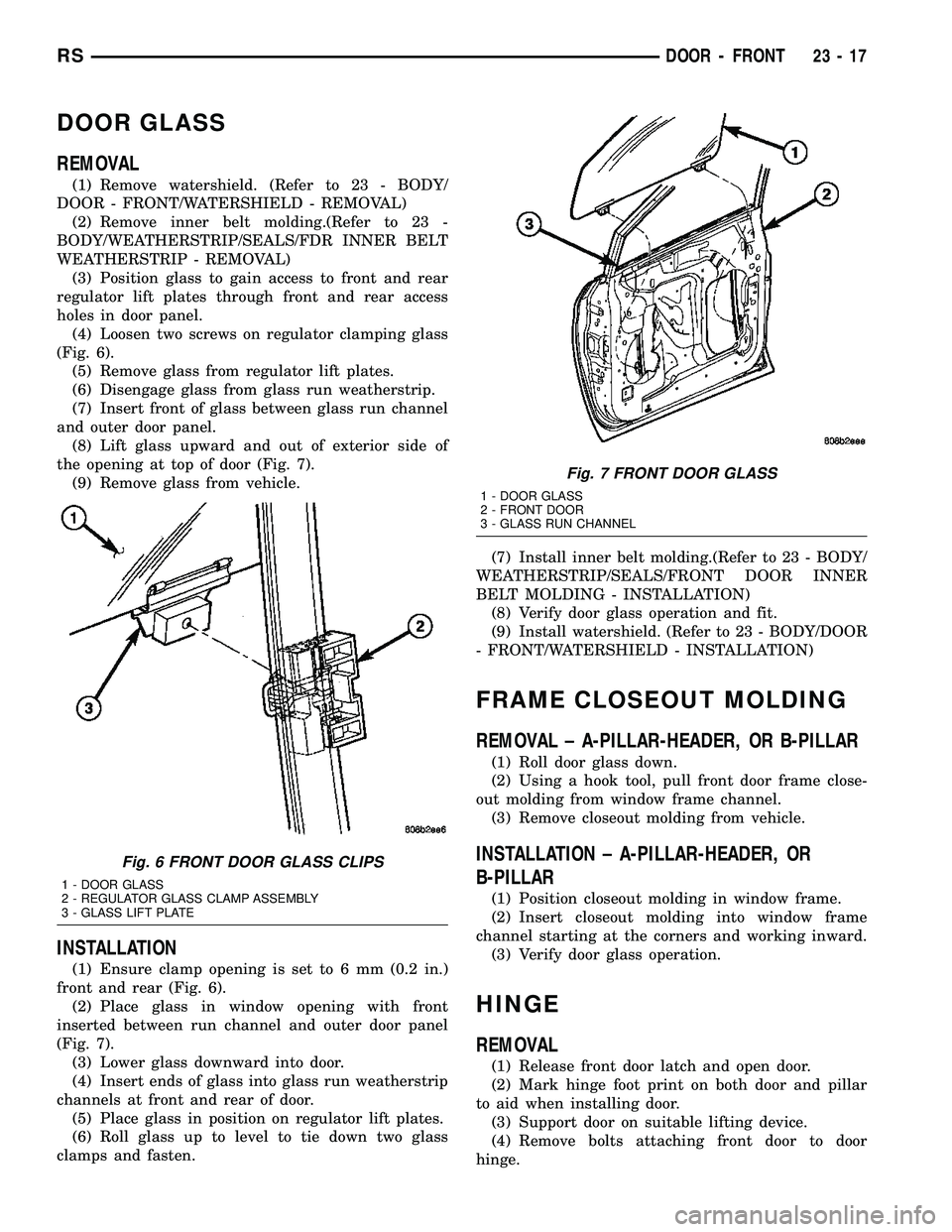
DOOR GLASS
REMOVAL
(1) Remove watershield. (Refer to 23 - BODY/
DOOR - FRONT/WATERSHIELD - REMOVAL)
(2) Remove inner belt molding.(Refer to 23 -
BODY/WEATHERSTRIP/SEALS/FDR INNER BELT
WEATHERSTRIP - REMOVAL)
(3) Position glass to gain access to front and rear
regulator lift plates through front and rear access
holes in door panel.
(4) Loosen two screws on regulator clamping glass
(Fig. 6).
(5) Remove glass from regulator lift plates.
(6) Disengage glass from glass run weatherstrip.
(7) Insert front of glass between glass run channel
and outer door panel.
(8) Lift glass upward and out of exterior side of
the opening at top of door (Fig. 7).
(9) Remove glass from vehicle.
INSTALLATION
(1) Ensure clamp opening is set to 6 mm (0.2 in.)
front and rear (Fig. 6).
(2) Place glass in window opening with front
inserted between run channel and outer door panel
(Fig. 7).
(3) Lower glass downward into door.
(4) Insert ends of glass into glass run weatherstrip
channels at front and rear of door.
(5) Place glass in position on regulator lift plates.
(6) Roll glass up to level to tie down two glass
clamps and fasten.(7) Install inner belt molding.(Refer to 23 - BODY/
WEATHERSTRIP/SEALS/FRONT DOOR INNER
BELT MOLDING - INSTALLATION)
(8) Verify door glass operation and fit.
(9) Install watershield. (Refer to 23 - BODY/DOOR
- FRONT/WATERSHIELD - INSTALLATION)
FRAME CLOSEOUT MOLDING
REMOVAL ± A-PILLAR-HEADER, OR B-PILLAR
(1) Roll door glass down.
(2) Using a hook tool, pull front door frame close-
out molding from window frame channel.
(3) Remove closeout molding from vehicle.
INSTALLATION ± A-PILLAR-HEADER, OR
B-PILLAR
(1) Position closeout molding in window frame.
(2) Insert closeout molding into window frame
channel starting at the corners and working inward.
(3) Verify door glass operation.
HINGE
REMOVAL
(1) Release front door latch and open door.
(2) Mark hinge foot print on both door and pillar
to aid when installing door.
(3) Support door on suitable lifting device.
(4) Remove bolts attaching front door to door
hinge.
Fig. 6 FRONT DOOR GLASS CLIPS
1 - DOOR GLASS
2 - REGULATOR GLASS CLAMP ASSEMBLY
3 - GLASS LIFT PLATE
Fig. 7 FRONT DOOR GLASS
1 - DOOR GLASS
2 - FRONT DOOR
3 - GLASS RUN CHANNEL
RSDOOR - FRONT23-17