Slow CHRYSLER VOYAGER 2004 Repair Manual
[x] Cancel search | Manufacturer: CHRYSLER, Model Year: 2004, Model line: VOYAGER, Model: CHRYSLER VOYAGER 2004Pages: 2585, PDF Size: 62.54 MB
Page 2220 of 2585

(4) Remove A-pillar trim panels.
(5) Place protective covers over instrument panel
and hood.
(6) Remove windshield molding. Using pliers, pull
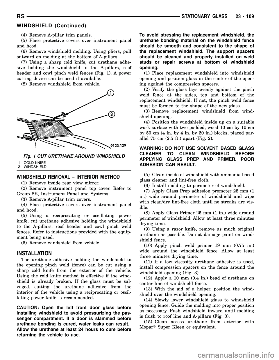
outward on molding at the bottom of A-pillars.
(7) Using a sharp cold knife, cut urethane adhe-
sive holding the windshield to the A-pillars, roof
header and cowl pinch weld fences (Fig. 1). A power
cutting device can be used if available.
(8) Remove windshield from vehicle.
WINDSHIELD REMOVAL ± INTERIOR METHOD
(1) Remove inside rear view mirror.
(2) Remove instrument panel top cover. Refer to
Group 8E, Instrument Panel and Systems.
(3) Remove A-pillar trim covers.
(4) Place protective covers over instrument panel
and hood.
(5) Using a reciprocating or oscillating power
knife, cut urethane adhesive holding the windshield
to the A-pillars, roof header and cowl pinch weld
fences. Refer to instructions provided with the equip-
ment being used.
(6) Remove windshield from vehicle.
INSTALLATION
The urethane adhesive holding the windshield to
the opening pinch weld (fence) can be cut using a
sharp cold knife from the exterior of the vehicle.
Using the cold knife method is effective if the wind-
shield is already broken. If the glass must be sal-
vaged, cutting the urethane adhesive from the
interior of the vehicle using a reciprocating or oscil-
lating power knife is recommended.
CAUTION: Open the left front door glass before
installing windshield to avoid pressurizing the pas-
senger compartment. If a door is slammed before
urethane bonding is cured, water leaks can result.
Allow the urethane at least 24 hours to cure before
returning the vehicle to use.To avoid stressing the replacement windshield, the
urethane bonding material on the windshield fence
should be smooth and consistent to the shape of
the replacement windshield. The support spacers
should be cleaned and properly installed on weld
studs or repair screws at bottom of windshield
opening.
(1) Place replacement windshield into windshield
opening and position glass in the center of the open-
ing against the compression spacers.
(2) Verify the glass lays evenly against the pinch
weld fence at the sides, top and bottom of the
replacement windshield. If not, the pinch weld fence
must be formed to the shape of the new glass.
(3) Remove replacement windshield from wind-
shield opening.
(4) Position the windshield inside up on a suitable
work surface with two padded, wood 10 cm by 10 cm
by 50 cm (4 in. by 4 in. by 20 in.) blocks, placed par-
allel 75 cm (2.5 ft.) apart (Fig. 2).
WARNING: DO NOT USE SOLVENT BASED GLASS
CLEANER TO CLEAN WINDSHIELD BEFORE
APPLYING GLASS PREP AND PRIMER. POOR
ADHESION CAN RESULT.
(5) Clean inside of windshield with ammonia based
glass cleaner and lint-free cloth.
(6) Install molding to perimeter of windshield.
(7) Apply Glass Prep adhesion promoter 25 mm (1
in.) wide around perimeter of windshield and wipe
with clean/dry lint-free cloth until no streaks are vis-
ible.
(8) Apply Glass Primer 25 mm (1 in.) wide around
perimeter of windshield. Allow at least three minutes
drying time.
(9) Using a razor knife, remove as much original
urethane as possible. Do not damage paint on wind-
shield fence.
(10) Apply pinch weld primer 19 mm (0.75 in.)
wide around the windshield fence. Allow at least
three minutes drying time.
(11) If a low viscosity urethane adhesive is used,
install compression spacers on the fence around the
windshield opening (Fig. 3).
(12) Apply a 10 mm (0.4 in.) bead of urethane on
center line of windshield fence.
(13) With the aid of a helper, position the wind-
shield over the windshield opening.
(14) Slowly lower windshield glass to windshield
opening fence. Guide the molding into proper position
as necessary. Push windshield inward until molding
is flush to roof line and A-pillars (Fig. 3).
(15) Clean access urethane from exterior with
MopartSuper Kleen or equivalent.
Fig. 1 CUT URETHANE AROUND WINDSHIELD
1 - COLD KNIFE
2 - WINDSHIELD
RSSTATIONARY GLASS23 - 109
WINDSHIELD (Continued)
Page 2223 of 2585

with clean/dry lint-free cloth until no streaks are vis-
ible.
(8) Apply Glass Primer 25 mm (1 in.) wide around
perimeter of rear window. Allow at least three min-
utes drying time.
(9) Apply Pinch weld Primer 19 mm (0.75 in.) wide
around the rear window fence. Allow at least three
minutes drying time.
(10) If a low viscosity urethane adhesive is used,
install compression spacers on the fence around the
rear window opening.
(11) Apply a 10 mm (0.4 in.) bead of urethane
along center line of rear window fence.
CAUTION: Be careful so that spacers do not con-
tamianate urethane bead.
(12) Apply 2 glass spacer clips to bottom edge of
glass, approximately 1.5 mm (0.6 in) inboard from
each corner.(13) With the aid of a helper, position the rear
window over the rear window opening and align the
reference marks.
(14) Slowly lower glass to rear window opening
fence. Ensure spacers on bottom edge of glass contact
sheet metal ledge. Then, push glass inward until
flush to liftgate surface.
(15) Clean excess urethane from exterior with
MopartSuper Kleen, or equivalent.
(16) Apply 150 mm (6 in.) lengths of 50 mm (2 in.)
masking tape spaced 250 mm (10 in.) apart to hold
molding in place until urethane cures.
(17) Install rear window wiper arm.
(18) Install interior trim.
(19) After urethane has cured, remove tape strips,
slide out bottom spacer clips, and then water test
rear window to verify repair.
23 - 112 STATIONARY GLASSRS
REAR DOOR GLASS (Continued)
Page 2400 of 2585

OPERATION - DUAL ZONE
²The two slide controls enable continuously vari-
able proportioning of the conditioned air.
²The mode control knob enables continuously
variable proportioning of air flow between modes and
has detents adjacent to each icon.
²The blower control provides four separate speeds
and an Off position.
²When the heater-A/C system is off, the HVAC
computer closes the recirculation door to prevent out-
side air from entering the passenger compartment.
²Interior air may be recirculated to speed up
heating or cooling in all modes except defrost and
mix by pressing the Recirculate button on the A/C-
heater control.
²To reduce humidity for rapid defogging, the A/C
compressor runs automatically in modes from ªmixº
to full defrost when outside temperatures are above
freezing.
²Air conditioning is available in any mode by
pressing the snowflake, A/C on/off button.
OPERATION - MANUAL THREE ZONE
FRONT CONTROL PANEL
²Primary control of the rear heater-A/C system is
on the instrument panel. This control allows the
driver to set the rear compartment fan speed, to turn
the rear heater-A/C system off, or to give control to
the intermediate seat occupants by switching to the
Rear position. When the rear heater-A/C system is
controlled from the instrument panel, rear air tem-
perature is based on the driver-side temperature con-
trol position, and the mode (floor or overhead air) is
based on the front control's mode position.
²The mode control knob enables continuously
variable proportioning of air flow between modes but
has detents adjacent to each icon.
²The blower control provides four separate speeds
and an Off position. When the heater-A/C system is
off, the HVAC computer closes the recirculation door
to prevent outside air from entering the passenger
compartment.
²Interior air may be recirculated to speed up
heating or cooling in all modes except defrost and
mix by pressing the Recirculate button on the control
panel.
²To reduce humidity for rapid defogging the A/C
compressor runs automatically in modes from ªmix'
to full defrost when outside temperatures are above
freezing.
²Air conditioning is available in any mode by
pressing the snowflake, A/C on/off, button.
REAR CONTROL PANEL
With the rear control active, temperature selection
dictates the air distribution mode (floor or overhead
air) of the rear unit: a cool temperature setting
directs flow to the overhead outlets and a warm tem-
perature setting to the floor.
OPERATION - THREE ZONE ATC
Comfort temperature or perceived temperature is
affected by air flow, sun levels on exposed skin, etc. The
air temperature may be higher or lower than the com-
fort temperature. Two infrared sensors in the instru-
ment panel center stack measure the temperature of
the occupants to determine their comfort level relative
to the selected comfort temperature. The integral
HVAC computer adjusts temperature and air flow rates
to maintain the customer-perceived comfort tempera-
ture. The air temperature in the passenger compart-
ment may be slightly higher or lower than the comfort
temperature at any time. For instance, on sunny sum-
mer days the air flow will probably be cooler than the
comfort temperature; on cold or cloudy days and at
night it will probably be slightly warmer. Infrared
Three-Zone Temperature Control provides side-to-side
and front-to-rear variations in comfort temperature set-
tings. The Infrared Three-Zone Automatic Temperature
Control fan provides a continuously variable air flow
rate to meet occupant comfort requirements.
FRONT CONTROL PANEL
²AUTO HI/LO± This system features two sets of
automatic control logic that allow either a rapid cool-
down rate or a somewhat slower cool-down rate with
less fan noise. HI-AUTO controls the system to reach
its assigned temperature quickly with a higher fan
speed. LO-AUTO controls the system to reach its
assigned temperature somewhat slower with less fan
noise. Both modes will automatically engage auto
recirculation.
²DE-FROST± The defrost function is active
when the rear window defogger function is active or
when the defog/defrost mode is selected.
²RECIRC± The RECIRC button will close the
air inlet door. If the system is in auto recirc (indica-
tor being displayed automatically), pressing the man-
ual recirc button will disable the auto recirc function
until one of the auto keys are pressed or the ignition
is cycled. If Auto HI/LO is pressed while manual
recirc is active, manual recirc will be deactivated.
²REAR WINDOW DEFOGGER± Pushing the
button sends a PCI bus message to the Intelligent
Power Module which controls the Rear Window
Defogger and side view mirror (if equipped) circuitry.
The defogger function will be active for 10 minutes
and can be turned off by a switch press. The defogger
will function while the control is in the ON mode.
RSHEATING & AIR CONDITIONING24-5
HEATING & AIR CONDITIONING (Continued)
Page 2517 of 2585

The following is a list of the monitored compo-
nents:
²Comprehensive Components
²Oxygen Sensor Monitor
²Oxygen Sensor Heater Monitor
²Catalyst Monitor
COMPREHENSIVE COMPONENTS
Along with the major monitors, OBD II requires
that the diagnostic system monitor any component
that could affect emissions levels. In many cases,
these components were being tested under OBD I.
The OBD I requirements focused mainly on testing
emissions-related components for electrical opens and
shorts.
However, OBD II also requires that inputs from
powertrain components to the PCM be tested for
rationality, and that outputs to powertrain compo-
nents from the PCM be tested forfunctionality.
Methods for monitoring the various Comprehensive
Component monitoring include:
(1) Circuit Continuity
²Open
²Shorted high
²Shorted to ground
(2) Rationality or Proper Functioning
²Inputs tested for rationality
²Outputs tested for functionality
NOTE: Comprehensive component monitors are
continuous. Therefore, enabling conditions do not
apply.
Input RationalityÐWhile input signals to the
PCM are constantly being monitored for electrical
opens and shorts, they are also tested for rationality.
This means that the input signal is compared against
other inputs and information to see if it makes sense
under the current conditions.
PCM sensor inputs that are checked for rationality
include:
²Manifold Absolute Pressure (MAP) Sensor
²Oxygen Sensor (O2S)
²Engine Coolant Temperature (ECT) Sensor
²Camshaft Position (CMP) Sensor
²Vehicle Speed Sensor
²Crankshaft Position (CKP) Sensor
²Intake/inlet Air Temperature (IAT) Sensor
²Throttle Position (TPS) Sensor
²Ambient Temperature Sensors
²Power Steering Switch
²Oxygen Sensor Heater
²Brake Switch
²Leak Detection Pump Switch or NVLD switch (if
equipped)
²P/N SwitchOutput FunctionalityÐPCM outputs are tested
for functionality in addition to testing for opens and
shorts. When the PCM provides a voltage to an out-
put component, it can verify that the command was
carried out by monitoring specific input signals for
expected changes. For example, when the PCM com-
mands the Idle Air Control (IAC) Motor to a specific
position under certain operating conditions, it expects
to see a specific (target) idle speed (RPM). If it does
not, it stores a DTC.
PCM outputs monitored for functionality include:
²Fuel Injectors
²Ignition Coils
²Idle Air Control
²Purge Solenoid
²EGR Solenoid (if equipped)
²LDP Solenoid or NVLD solenoid (if equipped)
²Radiator Fan Control
²Trans Controls
OXYGEN SENSOR (O2S) MONITOR
DESCRIPTIONÐEffective control of exhaust
emissions is achieved by an oxygen feedback system.
The most important element of the feedback system
is the O2S. The O2S is located in the exhaust path.
Once it reaches operating temperature 300É to 350ÉC
(572É to 662ÉF), the sensor generates a voltage that
is inversely proportional to the amount of oxygen in
the exhaust. When there is a large amount of oxygen
in the exhaust caused by a lean condition, the sensor
produces a low voltage, below 450 mV. When the oxy-
gen content is lower, caused by a rich condition, the
sensor produces a higher voltage, above 450mV (volt-
ages are offset by 2.5 volts on NGC vehicles).
The information obtained by the sensor is used to
calculate the fuel injector pulse width. The PCM is
programmed to maintain the optimum air/fuel ratio.
At this mixture ratio, the catalyst works best to
remove hydrocarbons (HC), carbon monoxide (CO)
and nitrous oxide (NOx) from the exhaust.
The O2S is also the main sensing element for the
EGR (if equipped), Catalyst and Fuel Monitors.
The O2S may fail in any or all of the following
manners:
²Slow response rate (Big Slope)
²Reduced output voltage (Half Cycle)
²Heater Performance
Slow Response Rate (Big Slope)ÐResponse rate
is the time required for the sensor to switch from
lean to rich signal output once it is exposed to a
richer than optimum A/F mixture or vice versa. As
the PCM adjusts the air/fuel ratio, the sensor must
be able to rapidly detect the change. As the sensor
ages, it could take longer to detect the changes in the
oxygen content of the exhaust gas. The rate of
change that an oxygen sensor experiences is called
25 - 2 EMISSIONS CONTROLRS
EMISSIONS CONTROL (Continued)
Page 2521 of 2585

FUEL INJECTOR MECHANICAL MALFUNCTIONS
The PCM cannot determine if a fuel injector is
clogged, the needle is sticking or if the wrong injector
is installed. However, these could result in a rich or
lean condition causing the PCM to store a diagnostic
trouble code for either misfire, an oxygen sensor, or
the fuel system.
EXCESSIVE OIL CONSUMPTION
Although the PCM monitors engine exhaust oxygen
content when the system is in closed loop, it cannot
determine excessive oil consumption.
THROTTLE BODY AIR FLOW
The PCM cannot detect a clogged or restricted air
cleaner inlet or filter element.
VACUUM ASSIST
The PCM cannot detect leaks or restrictions in the
vacuum circuits of vacuum assisted engine control
system devices. However, these could cause the PCM
to store a MAP sensor diagnostic trouble code and
cause a high idle condition.
PCM SYSTEM GROUND
The PCM cannot determine a poor system ground.
However, one or more diagnostic trouble codes may
be generated as a result of this condition. The mod-
ule should be mounted to the body at all times,
including when diagnostics are performed.
PCM CONNECTOR ENGAGEMENT
The PCM may not be able to determine spread or
damaged connector pins. However, it might store
diagnostic trouble codes as a result of spread connec-
tor pins.
DESCRIPTION - MONITORED SYSTEMS
There are new electronic circuit monitors that
check fuel, emission, engine and ignition perfor-
mance. These monitors use information from various
sensor circuits to indicate the overall operation of the
fuel, engine, ignition and emission systems and thus
the emissions performance of the vehicle.
The fuel, engine, ignition and emission systems
monitors do not indicate a specific component prob-
lem. They do indicate that there is an implied prob-
lem within one of the systems and that a specific
problem must be diagnosed.
If any of these monitors detect a problem affecting
vehicle emissions, the Malfunction Indicator (Check
Engine) Lamp will be illuminated. These monitors
generate Diagnostic Trouble Codes that can be dis-
played with the a DRBIIItscan tool.
The following is a list of the system monitors:
²EGR Monitor (if equipped)²Misfire Monitor
²Fuel System Monitor
²Oxygen Sensor Monitor
²Oxygen Sensor Heater Monitor
²Catalyst Monitor
²Evaporative System Leak Detection Monitor (if
equipped)
Following is a description of each system monitor,
and its DTC.
Refer to the appropriate Powertrain Diagnos-
tics Procedures manual for diagnostic proce-
dures.
OXYGEN SENSOR (O2S) MONITOR
Effective control of exhaust emissions is achieved
by an oxygen feedback system. The most important
element of the feedback system is the O2S. The O2S
is located in the exhaust path. Once it reaches oper-
ating temperatures of 300É to 350ÉC (572É to 662ÉF),
the sensor generates a voltage that is inversely pro-
portional to the amount of oxygen in the exhaust.
The information obtained by the sensor is used to
calculate the fuel injector pulse width. The PCM is
programmed to maintain the optimum air/fuel ratio.
At this mixture ratio, the catalyst works best to
remove hydrocarbons (HC), carbon monoxide (CO)
and nitrous oxide (NOx) from the exhaust.
The O2S is also the main sensing element for the
EGR (if equipped), Catalyst and Fuel Monitors.
The O2S may fail in any or all of the following
manners:
²Slow response rate
²Reduced output voltage
²Dynamic shift
²Shorted or open circuits
Response rate is the time required for the sensor to
switch from lean to rich once it is exposed to a richer
than optimum A/F mixture or vice versa. As the sen-
sor starts malfunctioning, it could take longer to
detect the changes in the oxygen content of the
exhaust gas.
The output voltage of the O2S ranges from 0 to 1
volt (voltages are offset by 2.5 volts on NGC vehi-
cles). A good sensor can easily generate any output
voltage in this range as it is exposed to different con-
centrations of oxygen. To detect a shift in the A/F
mixture (lean or rich), the output voltage has to
change beyond a threshold value. A malfunctioning
sensor could have difficulty changing beyond the
threshold value.
OXYGEN SENSOR HEATER MONITOR
If there is an oxygen sensor (O2S) DTC as well as
a O2S heater DTC, the O2S heater fault MUST be
repaired first. After the O2S fault is repaired, verify
that the heater circuit is operating correctly.
25 - 6 EMISSIONS CONTROLRS
EMISSIONS CONTROL (Continued)