brake sensor CHRYSLER VOYAGER 2004 Repair Manual
[x] Cancel search | Manufacturer: CHRYSLER, Model Year: 2004, Model line: VOYAGER, Model: CHRYSLER VOYAGER 2004Pages: 2585, PDF Size: 62.54 MB
Page 1234 of 2585

CONNECTOR NAME/NUMBER COLOR LOCATION FIG.
C313 (Rear Console) BK At Rear Console 34
C314 BK Left Side Liftgate 49
C315 (Power Liftgate) BK Right Side Liftgate 49
C316 (Power Sliding Door) BK Wire Track to Sliding Door N/S
C317 (Power Sliding Door) BK Right Sliding Door 32, 45
C318 (Trailer Tow) BK Left Quarter N/S
C320 DKGY Driver Power Seat on Seat Harness N/S
C321 DKGY Under Passenger Seat N/S
C322 (Memory) BK On Seat Harness to Body 32
C324 (Manual Sliding Door) BK Left Sliding Door N/S
C325 (Manual Sliding Door) BK Right Sliding Door 32
C326 YL At Driver Side Airbag N/S
C327 YL At Passenger Side Airbag N/S
C328 (Sunroof) Left Quarter Panel 47
C329 (Diesel) BK Near Fuel Tank N/S
C330 (Diesel) LTGY Near Throttle Body 15, 16
C331 (Diesel) BK/GY Left Rear Engine Compartment N/S
C332 (3 Zone ATC) BK/LTGN Near T/O for Right Rear Lamp
AssemblyN/S
C333 (Except Export DKGY Left Side Instrument Panel 21
Cabin Heater Assist C1 (Diesel) BK Top of Engine N/S
Cabin Heater Assist C2 (Diesel) BK Top of Engine N/S
Camshaft Position Sensor (Gas) BK Rear of Cylinder Head
Right Side of Engine11 , 1 7
Camshaft Position Sensor
(Diesel)BK Rear of Cylinder Head 15, 16
CD Changer Behind CD Changer N/S
Center High Mounted Stop Lamp BK At Lamp 49
Clockspring - C1 WT Steering Column 20, 21, 22, 23, 31
Clockspring - C2 YL Steering Column 20, 21, 22, 23, 31
Clockspring - C3 BK Steering Column N/S
Clockspring - C4 BK Steering Column N/S
Clutch Pedal Interlock Switch BK At Switch/Driver Side 42
Clutch Pedal Upstop Switch
(Diesel)RD At Switch/Driver Side 42
Controller Anti-Lock Brake BK Right Side of Engine Compartment 11, 16, 17, 18
Crank Case Ventilation Heater
(Diesel)BK Top of Cylinder Head 15
Crankshaft Position Sensor
(Diesel)BK Rear of Engine 16
Crankshaft Position Sensor (Gas) BK Rear of Engine 13, 17
Data Link Connector WT Lower Instrument Panel Near
Steering Column41, 42
Dosing Pump (Diesel) BK Top of Engine N/S
RS8W-91 CONNECTOR/GROUND/SPLICE LOCATION8W-91-3
CONNECTOR/GROUND/SPLICE LOCATION (Continued)
Page 1243 of 2585

CONNECTOR NAME/NUMBER COLOR LOCATION FIG.
Sentry Key Remote Entry Module
(Skreem)BK At Steering Column 20, 21, 22, 23, 31
Siren (United Kingdom) BK Left Front Body N/S
Speed Control Servo (Gas) BK Near Controller Antilock Brake 11, 17, 18
Sunroof Module (Except Export) BK At Sunroof N/S
Sunroof Switch (Except Export) Nat Near Overhead Console N/S
Thatcham Alarm Module C1
(United Kingdom)BK Top Right Side of Instrument Panel
Near SpeakerN/S
Throttle Position Sensor (Gas) GY On Throttle Body 10, 11, 17
Traction Control Switch BK Rear of Swtich 21, 22, 31
Trailer Tow Connector (Except
Export)BK Left Quarter Panel N/S
Transmission Range Sensor DKGY Top of Transmission 14, 19
Transmission Solenoid/Pressure
Switch AssemblyBK Side of Transmission 14, 18 19
Vehicle Speed Sensor (MTX) BK Rear of Transmission 16
Washer Fluid Level Switch BK Bottom of Reservoir 3
Washer Pump Motor BK Right Fender Well 3
Water in Fuel Sensor (Diesel) BK Left Rear Engine Compartment N/S
Wiper Module DKGY Left Side Cowl 6
GROUNDS
GROUND NUMBER LOCATION FIG.
G100 Body Ground Near Powertrain Control Module N/S
G101 Above Starter 13, 18
G102 Left Headlamp Area 1
G103 Above Starter 15
G200 Right Side of Instrument Panel 20, 24, 29
G201 Right Side of Instrument Panel 20, 24, 29
G202 Near Radio N/S
G300 Left B Pillar 32
G301 Right B Pillar 33, 39
G302 Left Rear Quarter 47
G303 Liftgate Ground 49
8W - 91 - 12 8W-91 CONNECTOR/GROUND/SPLICE LOCATIONRS
CONNECTOR/GROUND/SPLICE LOCATION (Continued)
Page 1355 of 2585
INTAKE MANIFOLD
DESCRIPTION
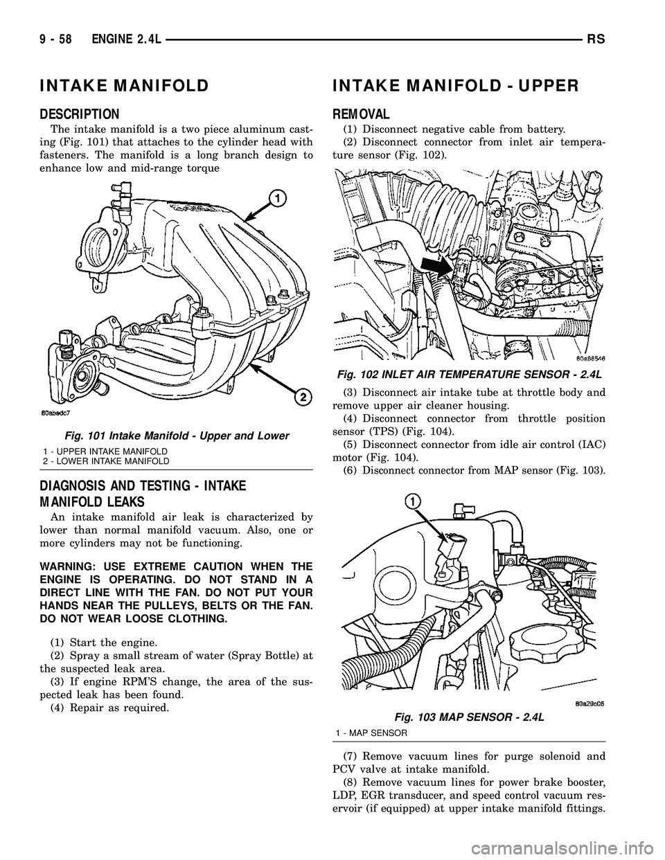
The intake manifold is a two piece aluminum cast-
ing (Fig. 101) that attaches to the cylinder head with
fasteners. The manifold is a long branch design to
enhance low and mid-range torque
DIAGNOSIS AND TESTING - INTAKE
MANIFOLD LEAKS
An intake manifold air leak is characterized by
lower than normal manifold vacuum. Also, one or
more cylinders may not be functioning.
WARNING: USE EXTREME CAUTION WHEN THE
ENGINE IS OPERATING. DO NOT STAND IN A
DIRECT LINE WITH THE FAN. DO NOT PUT YOUR
HANDS NEAR THE PULLEYS, BELTS OR THE FAN.
DO NOT WEAR LOOSE CLOTHING.
(1) Start the engine.
(2) Spray a small stream of water (Spray Bottle) at
the suspected leak area.
(3) If engine RPM'S change, the area of the sus-
pected leak has been found.
(4) Repair as required.
INTAKE MANIFOLD - UPPER
REMOVAL
(1) Disconnect negative cable from battery.
(2) Disconnect connector from inlet air tempera-
ture sensor (Fig. 102).
(3) Disconnect air intake tube at throttle body and
remove upper air cleaner housing.
(4) Disconnect connector from throttle position
sensor (TPS) (Fig. 104).
(5) Disconnect connector from idle air control (IAC)
motor (Fig. 104).
(6)
Disconnect connector from MAP sensor (Fig. 103).
(7) Remove vacuum lines for purge solenoid and
PCV valve at intake manifold.
(8) Remove vacuum lines for power brake booster,
LDP, EGR transducer, and speed control vacuum res-
ervoir (if equipped) at upper intake manifold fittings.
Fig. 101 Intake Manifold - Upper and Lower
1 - UPPER INTAKE MANIFOLD
2 - LOWER INTAKE MANIFOLD
Fig. 102 INLET AIR TEMPERATURE SENSOR - 2.4L
Fig. 103 MAP SENSOR - 2.4L
1 - MAP SENSOR
9 - 58 ENGINE 2.4LRS
Page 1356 of 2585
(9) Disconnect throttle and speed control (if
equipped) cables from throttle lever and bracket.
(Refer to 14 - FUEL SYSTEM/FUEL INJECTION/
THROTTLE CONTROL CABLE - REMOVAL)
(10) Remove the EGR tube. (Refer to 25 - EMIS-
SIONS CONTROL/EXHAUST GAS RECIRCULA-
TION/TUBE - REMOVAL)
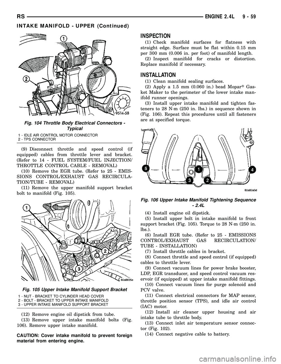
(11) Remove the upper manifold support bracket
bolt to manifold (Fig. 105).
(12) Remove engine oil dipstick from tube.
(13) Remove upper intake manifold bolts (Fig.
106). Remove upper intake manifold.
CAUTION: Cover intake manifold to prevent foreign
material from entering engine.
INSPECTION
(1) Check manifold surfaces for flatness with
straight edge. Surface must be flat within 0.15 mm
per 300 mm (0.006 in. per foot) of manifold length.
(2) Inspect manifold for cracks or distortion.
Replace manifold if necessary.
INSTALLATION
(1) Clean manifold sealing surfaces.
(2) Apply a 1.5 mm (0.060 in.) bead MopartGas-
ket Maker to the perimeter of the lower intake man-
ifold runner openings.
(3) Install upper intake manifold and tighten fas-
teners to 28 N´m (250 in. lbs.) in sequence shown in
(Fig. 106). Repeat this procedures until all fasteners
are at specified torque.
(4) Install engine oil dipstick.
(5) Install upper bolt in intake manifold to front
support bracket (Fig. 105). Torque to 28 N´m (250 in.
lbs.).
(6) Install EGR tube. (Refer to 25 - EMISSIONS
CONTROL/EXHAUST GAS RECIRCULATION/
TUBE - INSTALLATION)
(7) Install throttle cables in bracket.
(8) Connect throttle and speed control (if equipped)
cables to throttle lever.
(9) Connect vacuum lines for power brake booster,
LDP, EGR transducer, and speed control vacuum res-
ervoir (if equipped) at upper intake manifold fittings.
(10) Connect vacuum lines for purge solenoid and
PCV valve.
(11) Connect electrical connectors for MAP sensor,
throttle position sensor (TPS), and idle air control
(IAC) motor.
(12) Install air cleaner upper housing and air
intake tube to throttle body.
(13) Connect inlet air temperature sensor connec-
tor (Fig. 102).
(14) Connect negative cable to battery.
Fig. 104 Throttle Body Electrical Connectors -
Typical
1 - IDLE AIR CONTROL MOTOR CONNECTOR
2 - TPS CONNECTOR
Fig. 105 Upper Intake Manifold Support Bracket
1 - NUT - BRACKET TO CYLINDER HEAD COVER
2 - BOLT - BRACKET TO UPPER INTAKE MANIFOLD
3 - UPPER INTAKE MANIFOLD SUPPORT BRACKET
Fig. 106 Upper Intake Manifold Tightening Sequence
- 2.4L
RSENGINE 2.4L9-59
INTAKE MANIFOLD - UPPER (Continued)
Page 1384 of 2585

(11) Disconnect the throttle cables from the throt-
tle body.
(12) Disconnect the MAP, IAC, and TPS electrical
connectors.
(13) Disconnect the EGR transducer electrical con-
nector (if equipped).
(14) Disconnect the vacuum hoses from throttle
body.
(15) Disconnect the brake booster and speed con-
trol vacuum hoses.
(16) Disengage wire harness clip from the right
side engine mount.
(17) Remove the power steering reservoir from
mounting position and set aside.Do notdisconnect
hose.
(18) Disconnect ground strap from rear of cylinder
head.
(19) Disconnect engine coolant temperature (ECT)
sensor and ignition coil electrical connectors.
(20) Disconnect the fuel injector electrical harness
connector and disengage clip from support bracket.
(21) Disconnect camshaft and crankshaft position
sensor electrical connectors.
(22) Evacuate air conditioning system. Refer to 24
- HEATING & AIR CONDITIONING.
(23) Disconnect A/C compressor electrical connec-
tor.
(24) Disconnect the A/C lines from compressor.
Cover and seal all openings of hoses and compressor.
(25) Remove the radiator upper hose.
(26) Disengage electrical harness clip at transaxle
dipstick tube.
(27) Remove transaxle dipstick tube. Seal opening
using a suitable plug.
NOTE: When the transaxle cooler lines are removed
from the rolled-groove type fittings at the transaxle,
damage to the inner wall of the hose will occur. To
prevent prevent potential leakage, the cooler hoses
must be cut off flush at the transaxle fitting, and a
service cooler hose splice kit must be installed
upon reassembly.
(28) Using a blade or suitable hose cutter, cut
transaxle oil cooler lines off flush with fittings. Plug
cooler lines and fittings to prevent debris from enter-
ing transaxle or cooler circuit. A service splice kit will
be installed upon reassembly.
(29) Disconnect transaxle shift linkage and electri-
cal connectors.
(30)
Raise vehicle on hoist and drain the engine oil.
(31) Remove the axle shafts. (Refer to 3 - DIFFER-
ENTIAL & DRIVELINE/HALF SHAFT - REMOVAL)
(32) Remove crossmember cradle plate (Fig. 6).
(33)AWD equipped:Remove the power transfer
unit (PTU) (Refer to 21 - TRANSMISSION/TRANS-
AXLE/POWER TRANSFER UNIT - REMOVAL).(34) Disconnect exhaust pipe from the manifold
(Fig. 7).
(35) Remove front engine mount and bracket as an
assembly.
(36) Remove the engine rear mount bracket.
(37) Remove the engine to transaxle struts (Fig. 8).
(38) Remove transaxle case cover (Fig. 8).
(39) Remove flex plate to torque converter bolts.
Mark torque converter to flex plate for orientation for
reassembly.
(40) Remove the power steering pressure hose sup-
port clip attaching bolt.
Fig. 6 Crossmember Cradle Plate
1 - CRADLE PLATE
Fig. 7 Catalytic Converter to Exhaust Manifold
1 - FLAG NUT
2 - GASKET
3 - BOLT
4 - CATALYTIC CONVERTER
RSENGINE 3.3/3.8L9-87
ENGINE 3.3/3.8L (Continued)
Page 1387 of 2585

(8) Install the generator and wiring harness (Refer
to 8 - ELECTRICAL/CHARGING/GENERATOR -
INSTALLATION).
(9) Raise vehicle.
(10) Attach wiring harness support clip to the
engine oil dipstick tube.
(11) Connect oil pressure switch electrical connec-
tor.
(12) Install the A/C compressor.
(13) Install the water pump pulley.
(14) Connect the radiator lower hose.(15) Install the accessory drive belt and splash
shield (Refer to 7 - COOLING/ACCESSORY DRIVE/
DRIVE BELTS - INSTALLATION).
(16) Connect the engine block heater electrical con-
nector (if equipped).
(17) Connect the knock sensor electrical connector
(3.8L only).
(18) Install the torque converter to flex plate bolts.
(19) Install the transaxle case cover (Fig. 8).
(20) Install the powertrain struts (Fig. 8).
(21) Install the engine rear mount bracket.
(22) Install the engine front mount and bracket
assembly.
(23)AWD equipped;Install the power transfer
unit (PTU) (Refer to 21 - TRANSMISSION/TRANS-
AXLE/POWER TRANSFER UNIT - INSTALLA-
TION).
(24) Install the axle shafts (Refer to 3 - DIFFER-
ENTIAL & DRIVELINE/HALF SHAFT - INSTALLA-
TION).
(25) Connect exhaust pipe to manifold (Fig. 7).
(26) Install crossmember cradle plate (Fig. 6).
(27) Lower vehicle.
(28) Connect transaxle shift linkage.
(29) Connect transaxle electrical connectors.
(30) Remove plugs from transmission cooler hoses
and install transaxle oil cooler line service splice kit.
Refer to instructions included with kit.
(31) Install transaxle dipstick tube and attach
electrical harness clip.
(32) Connect the A/C lines to compressor.
(33) Connect the A/C compressor electrical connec-
tor.
(34) Evacuate and recharge A/C system.
(35) Connect crankshaft and camshaft position
sensors.
(36) Connect the fuel injector electrical harness
connector and engage clip to support bracket.
(37) Connect engine coolant temperature (ECT)
sensor and ignition coil electrical connectors.
(38) Connect the ground strap to rear of cylinder
head.
(39) Install power steering reservoir.
(40) Engage wire harness clip to engine right side
mount.
(41) Connect the brake booster and speed control
vacuum hoses.
(42) Connect the vacuum hoses to the throttle
body.
(43) Connect the EGR transducer electrical connec-
tor (if equipped).
(44) Connect the TPS, IAC, and MAP sensor elec-
trical connectors.
(45) Connect throttle cables to throttle body.
(46) Install the radiator fans (Refer to 7 - COOL-
ING/ENGINE/RADIATOR FAN - INSTALLATION).
Fig. 13 Right Mount to Engine
1 - BOLT
2 - MOUNT BRACKET
3 - ENGINE RIGHT MOUNT ASSEMBLY
Fig. 14 LEFT MOUNT TO FRAME BRACKET
1 - FRAME BRACKET
2 - FRAME RAIL - LEFT
3 - BOLT
4 - TRANSAXLE MOUNT
9 - 90 ENGINE 3.3/3.8LRS
ENGINE 3.3/3.8L (Continued)
Page 1442 of 2585
DIAGNOSIS AND TESTING - INTAKE
MANIFOLD LEAKS
An intake manifold air leak is characterized by
lower than normal manifold vacuum. Also, one or
more cylinders may not be functioning.
WARNING: USE EXTREME CAUTION WHEN THE
ENGINE IS OPERATING. DO NOT STAND IN A
DIRECT LINE WITH THE FAN. DO NOT PUT YOUR
HANDS NEAR THE PULLEYS, BELTS OR THE FAN.
DO NOT WEAR LOOSE CLOTHING.
(1) Start the engine.
(2) Spray a small stream of water (Spray Bottle) at
the suspected leak area.
(3) If engine RPM'S change, the area of the sus-
pected leak has been found.
(4) Repair as required.
INTAKE MANIFOLD - UPPER
STANDARD PROCEDURE
STANDARD PROCEDURE - MANIFOLD
STRIPPED THREAD REPAIR
The composite upper intake manifold thread
bosses, if stripped out, can be repaired by utilizing a
repair screw available through Mopartparts. Repair
screws are available for the following manifold
attached components:
²MAP sensor
²Power steering reservoir
²EGR tube
²Throttle cable bracket
The repair screws require a unique tightening
torque specification from the original screw. Refer to
the following chart for specification.
DESCRIPTION TORQUE*
STRIP-OUT REPAIR SCREWS ONLY
MAP Sensor Repair
Screw4 N´m (35 in. lbs.)
Power Steering Reservoir
Repair Screw9 N´m (80 in. lbs.)
EGR Tube Attaching
Repair Screw9 N´m (80 in. lbs.)
Throttle Cable Bracket
Repair Screw9 N´m (80 in. lbs.)
*Install Slowly Using Hand Tools Only
STANDARD PROCEDURE - INTAKE MANIFOLD
VACUUM PORT REPAIR
The composite intake manifold vacuum ports can
be repaired. Although, if the manifold plenum cham-
ber is damaged or cracked, the manifold must be
replaced.
To repair a broken or damaged vacuum nipple
(port) on the composite intake manifold, perform the
following procedure:
PARTS REQUIRED TOOLS REQUIRED
´ Brass Nipple ± 1/49
O.D. x 1/89pipe thread
(LDP/Speed Control Port)´ Pipe Tap ± 1/89-18
NPT
´ Drill Bit ± 11/329
´ File/Sandpaper
´ Brass Nipple ± 1/29
O.D. x 1/49pipe thread
(Brake Booster Port)´ Pipe Tap ± 1/49-18
NPT
´ Drill Bit ± 7/169
´ File/Sandpaper
NOTE: While performing this procedure, avoid get-
ting the manifold material residue into the plenum
chamber.
(1) File or sand the remaining port back until a
flat surface is obtained (plane normal to nipple (port)
axis).
(2) Drill out the nipple (port) base using a 7/16º
(brake booster port) or 11/32º (LDP/speed control port
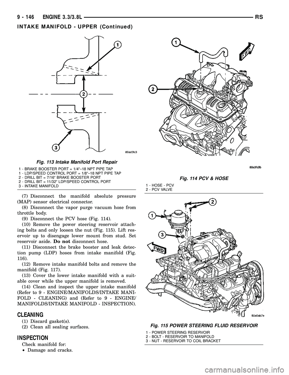
) drill bit (Fig. 113).
(3) Using a 1/4º±18 NPT (brake booster port) or
1/8º±18 NPT (LDP/speed control port ) pipe tap, cut
internal threads (Fig. 113). Use caution to start tap
in a axis same as original nipple.
(4) Apply MopartThread Sealant to threads of
repair nipple(s).
(5) Install repair nipple(s). Do not over torque
repair nipple(s).
REMOVAL - UPPER INTAKE MANIFOLD
(1) Disconnect battery negative cable.
(2) Disconnect inlet air temperature (IAT) sensor
electrical connector.
(3) Remove air inlet resonator to throttle body
hose assembly.
(4) Disconnect throttle and speed control cables
from throttle body (Refer to 14 - FUEL SYSTEM/
FUEL INJECTION/THROTTLE CONTROL CABLE -
REMOVAL).
(5) Disconnect make-up air hose support clip from
throttle cable bracket.
(6) Disconnect the automatic idle speed (AIS)
motor and throttle position sensor (TPS) wiring con-
nectors from throttle body.
RSENGINE 3.3/3.8L9 - 145
INTAKE MANIFOLD (Continued)
Page 1443 of 2585
(7) Disconnect the manifold absolute pressure
(MAP) sensor electrical connector.
(8) Disconnect the vapor purge vacuum hose from
throttle body.
(9) Disconnect the PCV hose (Fig. 114).
(10) Remove the power steering reservoir attach-
ing bolts and only loosen the nut (Fig. 115). Lift res-
ervoir up to disengage lower mount from stud. Set
reservoir aside.Do notdisconnect hose.
(11) Disconnect the brake booster and leak detec-
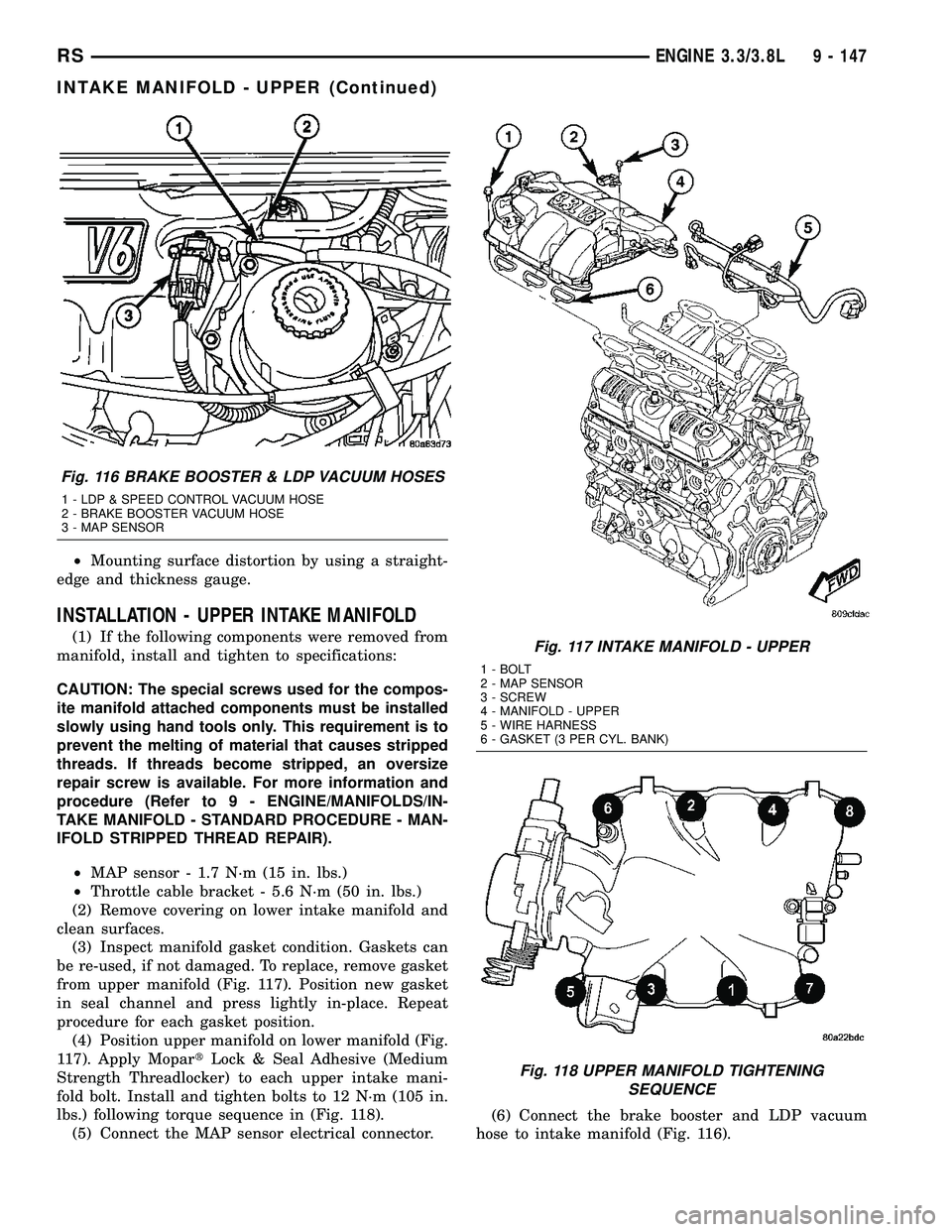
tion pump (LDP) hoses from intake manifold (Fig.
116).
(12) Remove intake manifold bolts and remove the
manifold (Fig. 117).
(13) Cover the lower intake manifold with a suit-
able cover while the upper manifold is removed.
(14) Clean and inspect the upper intake manifold
(Refer to 9 - ENGINE/MANIFOLDS/INTAKE MANI-
FOLD - CLEANING) and (Refer to 9 - ENGINE/
MANIFOLDS/INTAKE MANIFOLD - INSPECTION).
CLEANING
(1) Discard gasket(s).
(2) Clean all sealing surfaces.
INSPECTION
Check manifold for:
²Damage and cracks.
Fig. 113 Intake Manifold Port Repair
1 - BRAKE BOOSTER PORT = 1/49±18 NPT PIPE TAP
1 - LDP/SPEED CONTROL PORT = 1/89±18 NPT PIPE TAP
2 - DRILL BIT = 7/169BRAKE BOOSTER PORT
2 - DRILL BIT = 11/329LDP/SPEED CONTROL PORT
3 - INTAKE MANIFOLD
Fig. 114 PCV & HOSE
1 - HOSE - PCV
2 - P C V VA LV E
Fig. 115 POWER STEERING FLUID RESERVOIR
1 - POWER STEERING RESERVOIR
2 - BOLT - RESERVOIR TO MANIFOLD
3 - NUT - RESERVOIR TO COIL BRACKET
9 - 146 ENGINE 3.3/3.8LRS
INTAKE MANIFOLD - UPPER (Continued)
Page 1444 of 2585
²Mounting surface distortion by using a straight-
edge and thickness gauge.
INSTALLATION - UPPER INTAKE MANIFOLD
(1) If the following components were removed from
manifold, install and tighten to specifications:
CAUTION: The special screws used for the compos-
ite manifold attached components must be installed
slowly using hand tools only. This requirement is to
prevent the melting of material that causes stripped
threads. If threads become stripped, an oversize
repair screw is available. For more information and
procedure (Refer to 9 - ENGINE/MANIFOLDS/IN-
TAKE MANIFOLD - STANDARD PROCEDURE - MAN-
IFOLD STRIPPED THREAD REPAIR).
²MAP sensor - 1.7 N´m (15 in. lbs.)
²Throttle cable bracket - 5.6 N´m (50 in. lbs.)
(2) Remove covering on lower intake manifold and
clean surfaces.
(3) Inspect manifold gasket condition. Gaskets can
be re-used, if not damaged. To replace, remove gasket
from upper manifold (Fig. 117). Position new gasket
in seal channel and press lightly in-place. Repeat
procedure for each gasket position.
(4) Position upper manifold on lower manifold (Fig.
117). Apply MopartLock & Seal Adhesive (Medium
Strength Threadlocker) to each upper intake mani-
fold bolt. Install and tighten bolts to 12 N´m (105 in.
lbs.) following torque sequence in (Fig. 118).
(5) Connect the MAP sensor electrical connector.(6) Connect the brake booster and LDP vacuum
hose to intake manifold (Fig. 116).
Fig. 116 BRAKE BOOSTER & LDP VACUUM HOSES
1 - LDP & SPEED CONTROL VACUUM HOSE
2 - BRAKE BOOSTER VACUUM HOSE
3 - MAP SENSOR
Fig. 117 INTAKE MANIFOLD - UPPER
1 - BOLT
2 - MAP SENSOR
3 - SCREW
4 - MANIFOLD - UPPER
5 - WIRE HARNESS
6 - GASKET (3 PER CYL. BANK)
Fig. 118 UPPER MANIFOLD TIGHTENING
SEQUENCE
RSENGINE 3.3/3.8L9 - 147
INTAKE MANIFOLD - UPPER (Continued)
Page 1505 of 2585

REMOVAL
The front cradle crossmember must be installed in
the design location to achieve proper front end sus-
pension alignment. If the cradle crossmember is
removed without applying reference marks on the
frame rails, align the cradle crossmember according
to the dimensions provided in this group.
NOTE: If the caged nuts in the frame rails become
damaged and cannot be reused, a replacement nut
can be obtained through MoparT(Fig. 10).
REMOVAL
(1) Disconnect battery negative cable.
(2) Remove steering column lower cover from
instrument panel (Refer to 23 - BODY/INSTRU-
MENT PANEL/STEERING COLUMN OPENING
COVER - REMOVAL).
(3) Remove steering column cover backing plate
(Refer to 23 - BODY/INSTRUMENT PANEL/STEER-
ING COLUMN COVER BACKING PLATE -
REMOVAL).
(4) Position steering so front wheels are straight
ahead.
CAUTION: Do not rotate steering wheel after disen-
gaging lower coupling from steering gear, damage
to air bag clock spring can result.
(5) Remove clinch bolt attaching steering column
coupling to steering gear shaft (Fig. 11).
(6) Remove steering column coupling from tele-
scoping steering gear shaft.(7) Hoist vehicle and support on safety stands.
(8) Position a drain pan under power steering
pump and oil return hose coupling.
(9) Using a hose pinch-off pliers (C-4390), pinch
power steering oil return hose off between the cross-
member coupling and the pump.
(10) Loosen hose clamp at the cradle crossmember
coupling.
(11) Disconnect return hose from metal tube.
(12) While holding pressure relief valve nut on
back of power steering pump, Remove flare nut
attaching high pressure hose to back of pump.
(13) Remove high pressure hose from pump.
(14) Allow power steering fluid to drain into pan.
(15) Remove bolts attaching anti-lock brake sensor
leads to cradle crossmember.
(16) Position anti-lock brake leads out of the way.
(17) Disconnect stabilizer bar links from ends of
stabilizer bar.
(18) Disconnect lower ball joints from lower steer-
ing knuckles (Refer to 2 - SUSPENSION/FRONT/
LOWER BALL JOINT - REMOVAL).
(19) Remove the rear engine mount heat shield
(Fig. 12).
(20) Remove through bolt attaching rear engine
mount to cradle crossmember (Fig. 13).
(21) Using paint or grease pencil, mark outline of
cradle crossmember on frame rails to aid installation.
(22) Support cradle crossmember on suitable lift-
ing device (Fig. 15).
(23) Remove bolts attaching crossmember to front
frame rails (Fig. 14).
(24) Remove cradle crossmember from vehicle (Fig.
15).
Fig. 10 FRONT CRADLE CROSSMEMBER CAGED
NUT
1 - BRACKET
2 - CAGED NUT
Fig. 11 STEERING COUPLING
1 - STEERING SHAFT BOOT
2 - STEERING SHAFT
3 - CROSSMEMBER
4 - STEERING GEAR
5 - MOUNT
6 - TRANSAXLE
13 - 10 FRAME & BUMPERSRS
FRONT CRADLE CROSSMEMBER (Continued)