oil temperature CHRYSLER VOYAGER 2004 Repair Manual
[x] Cancel search | Manufacturer: CHRYSLER, Model Year: 2004, Model line: VOYAGER, Model: CHRYSLER VOYAGER 2004Pages: 2585, PDF Size: 62.54 MB
Page 1387 of 2585

(8) Install the generator and wiring harness (Refer
to 8 - ELECTRICAL/CHARGING/GENERATOR -
INSTALLATION).
(9) Raise vehicle.
(10) Attach wiring harness support clip to the
engine oil dipstick tube.
(11) Connect oil pressure switch electrical connec-
tor.
(12) Install the A/C compressor.
(13) Install the water pump pulley.
(14) Connect the radiator lower hose.(15) Install the accessory drive belt and splash
shield (Refer to 7 - COOLING/ACCESSORY DRIVE/
DRIVE BELTS - INSTALLATION).
(16) Connect the engine block heater electrical con-
nector (if equipped).
(17) Connect the knock sensor electrical connector
(3.8L only).
(18) Install the torque converter to flex plate bolts.
(19) Install the transaxle case cover (Fig. 8).
(20) Install the powertrain struts (Fig. 8).
(21) Install the engine rear mount bracket.
(22) Install the engine front mount and bracket
assembly.
(23)AWD equipped;Install the power transfer
unit (PTU) (Refer to 21 - TRANSMISSION/TRANS-
AXLE/POWER TRANSFER UNIT - INSTALLA-
TION).
(24) Install the axle shafts (Refer to 3 - DIFFER-
ENTIAL & DRIVELINE/HALF SHAFT - INSTALLA-
TION).
(25) Connect exhaust pipe to manifold (Fig. 7).
(26) Install crossmember cradle plate (Fig. 6).
(27) Lower vehicle.
(28) Connect transaxle shift linkage.
(29) Connect transaxle electrical connectors.
(30) Remove plugs from transmission cooler hoses
and install transaxle oil cooler line service splice kit.
Refer to instructions included with kit.
(31) Install transaxle dipstick tube and attach
electrical harness clip.
(32) Connect the A/C lines to compressor.
(33) Connect the A/C compressor electrical connec-
tor.
(34) Evacuate and recharge A/C system.
(35) Connect crankshaft and camshaft position
sensors.
(36) Connect the fuel injector electrical harness
connector and engage clip to support bracket.
(37) Connect engine coolant temperature (ECT)
sensor and ignition coil electrical connectors.
(38) Connect the ground strap to rear of cylinder
head.
(39) Install power steering reservoir.
(40) Engage wire harness clip to engine right side
mount.
(41) Connect the brake booster and speed control
vacuum hoses.
(42) Connect the vacuum hoses to the throttle
body.
(43) Connect the EGR transducer electrical connec-
tor (if equipped).
(44) Connect the TPS, IAC, and MAP sensor elec-
trical connectors.
(45) Connect throttle cables to throttle body.
(46) Install the radiator fans (Refer to 7 - COOL-
ING/ENGINE/RADIATOR FAN - INSTALLATION).
Fig. 13 Right Mount to Engine
1 - BOLT
2 - MOUNT BRACKET
3 - ENGINE RIGHT MOUNT ASSEMBLY
Fig. 14 LEFT MOUNT TO FRAME BRACKET
1 - FRAME BRACKET
2 - FRAME RAIL - LEFT
3 - BOLT
4 - TRANSAXLE MOUNT
9 - 90 ENGINE 3.3/3.8LRS
ENGINE 3.3/3.8L (Continued)
Page 1410 of 2585

CYLINDER BORE
NOTE: The cylinder bores should be measured at
normal room temperature, 21ÉC (70ÉF).
The cylinder walls should be checked for out-of-
round and taper with Tool C119 or equivalent (Fig.
45) (Refer to 9 - ENGINE - SPECIFICATIONS). If
the cylinder walls are badly scuffed or scored, the
cylinder block should be replaced, and new pistons
and rings fitted.
Measure the cylinder bore at three levels in direc-
tions A and B (Fig. 45). Top measurement should be
10 mm (3/8 in.) down and bottom measurement
should be 10 mm (3/8 in.) up from bottom of bore.
(Refer to 9 - ENGINE - SPECIFICATIONS).
HYDRAULIC LIFTERS (CAM IN
BLOCK)
DESCRIPTION
The hydraulic lifters are a roller type design and
are positioned in the cylinder block. The lifters are
aligned and retained by a yoke and a retainer (Fig.
47).Lifter alignment is maintained by machined flats
on lifter body. Lifters are fitted in pairs into six
aligning yokes. The aligning yokes are secured by a
yoke retainer (Fig. 47).
DIAGNOSIS AND TESTING - HYDRAULIC
LIFTERS
HYDRAULIC LIFTERS DIAGNOSIS - PRELIMINARY
STEP
Before disassembling any part of the engine to cor-
rect lifter noise, check the engine oil pressure. (Refer
to 9 - ENGINE/LUBRICATION - DIAGNOSIS AND
TESTING)
Check engine oil level. The oil level in the pan
should never be above the MAX mark on dipstick, or
below the MIN mark. Either of these two conditions
could cause noisy lifters.
OIL LEVEL TOO HIGH
If oil level is above the MAX mark on dipstick, it is
possible for the connecting rods to dip into the oil
while engine is running and create foaming. Foam in
oil pan would be fed to the hydraulic lifters by the oil
pump causing them to become soft and allow valves
to seat noisily.
OIL LEVEL TOO LOW
Low oil level may allow pump to take in air which
when fed to the lifters it causes them to become soft
and allows valves to seat noisily. Any leaks on intake
side of pump, through which air can be drawn, will
create the same lifter noise. Check the lubrication
system from the intake strainer to the oil pump
cover, including the relief valve retainer cap. When
lifter noise is due to aeration, it may be intermittent
or constant, and usually more than one lifter will be
noisy. When oil level and leaks have been corrected,
the engine should be operated at fast idle to allow all
of the air inside of the lifters to be bled out.
VALVE TRAIN NOISE
To determine source of valve train noise, operate
engine at idle with cylinder head covers removed and
listen for source of the noise.
NOTE: Worn valve guides or cocked springs are
sometimes mistaken for noisy lifters. If such is the
case, noise may be dampened by applying side
thrust on the valve spring. If noise is not apprecia-
bly reduced, it can be assumed the noise is in the
tappet. Inspect the rocker arm push rod sockets
and push rod ends for wear.
Fig. 45 Checking Cylinder Bore Size
RSENGINE 3.3/3.8L9 - 113
ENGINE BLOCK (Continued)
Page 1411 of 2585

Valve lifter noise ranges from light noise to a
heavy click. A light noise is usually caused by exces-
sive leak-down around the unit plunger which will
necessitate replacing the lifter, or by the plunger par-
tially sticking in the lifter body cylinder. A heavy
click is caused either by a lifter check valve not seat-
ing, or by foreign particles becoming wedged between
the plunger and the lifter body causing the plunger
to stick in the down position. This heavy click will be
accompanied by excessive clearance between the
valve stem and rocker arm as valve closes. In either
case, lifter assembly should be removed for inspec-
tion.
REMOVAL
(1) Remove the cylinder head(s). (Refer to 9 -
ENGINE/CYLINDER HEAD - REMOVAL)
(2) Remove the yoke retainer and aligning yokes
(Fig. 47).
(3) Remove the hydraulic lifters. If necessary use
Special Tool C-4129, or equivalent to remove lifters
from bores. If lifters are to be reused, identify each
lifter to ensure installation in original location.
INSTALLATION
(1) Lubricate the lifters with engine oil.
NOTE: Position the lifter in bore with the lubrication
hole facing upward (Fig. 46).
(2) Install the hydraulic lifters with the lubrication
hole facing upward towards middle of block (Fig. 46).
Install lifters in original positions, if reused.(3) Install lifter aligning yokes (Fig. 47).
(4) Install yoke retainer and torque screws to 12
N´m (105 in. lbs.) (Fig. 47).
(5) Install the cylinder heads. (Refer to 9 -
ENGINE/CYLINDER HEAD - INSTALLATION)
(6) Start and operate engine. Warm up to normal
operating temperature.
CAUTION: To prevent damage to valve mechanism,
engine must not be run above fast idle until all
hydraulic lifters have filled with oil and have
become quiet.
Fig. 46 LIFTER LUBRICATION HOLE
Fig. 47 Lifter Aligning Yoke and Retainer
1 - YOKE RETAINER
2 - BOLT - YOKE RETAINER
3 - ALIGNING YOKE
4 - HYDRAULIC LIFTER
9 - 114 ENGINE 3.3/3.8LRS
HYDRAULIC LIFTERS (CAM IN BLOCK) (Continued)
Page 1414 of 2585

(1) Before installing the nuts the threads should
be oiled with engine oil.
(2) Install nuts finger tight on each bolt then alter-
nately torque each nut to assemble the cap properly.
(3) Tighten the nuts to 54 N´m PLUS 1/4 turn (40
ft. lbs. PLUS 1/4 turn).
(4) Using a feeler gauge, check connecting rod side
clearance (Fig. 52). Refer to Engine Specifications
(Refer to 9 - ENGINE - SPECIFICATIONS).
STANDARD PROCEDURE - FITTING PISTONS
The piston and cylinder wall must be clean and
dry. Piston diameter should be measured 90 degrees
to piston pin at size location shown in (Fig. 53). Cyl-
inder bores should be measured halfway down the
cylinder bore and transverse to the engine crankshaft
center line shown in (Fig. 54). Refer to Engine Spec-
ifications (Refer to 9 - ENGINE - SPECIFICA-
TIONS).Pistons and cylinder bores should be
measured at normal room temperature, 21ÉC
(70ÉF).
REMOVAL
(1) Disconnect negative cable from battery.
(2) Remove the cylinder heads. (Refer to 9 -
ENGINE/CYLINDER HEAD - REMOVAL)
(3) Remove the oil pan. (Refer to 9 - ENGINE/LU-
BRICATION/OIL PAN - REMOVAL)
(4) Remove the top ridge of cylinder bores with a
reliable ridge reamer, if necessary, before removing
pistons from cylinder block.Be sure to keep tops
of pistons covered during this operation. Pis-
tons and connecting rods must be removed
from top of cylinder block. When removing pis-
ton and connecting rod assemblies from the
engine, rotate crankshaft so that each connect-
ing rod is centered in cylinder bore.
(5) Inspect connecting rods and connecting rod
caps for cylinder identification. Identify them, if nec-
essary (Fig. 55).Fig. 52 Checking Connecting Rod Side Clearance
Fig. 53 Piston Measurement Locations
1 - 39.8 mm (1.56 in. ) 3.3L ENGINE
2 - 33.0 mm (1.29 in.) 3.8L ENGINE
Fig. 54 Checking Cylinder Bore Size
Fig. 55 Identify Connecting Rod to Cylinder
1 - CYLINDER NUMBER
RSENGINE 3.3/3.8L9 - 117
PISTON & CONNECTING ROD (Continued)
Page 1445 of 2585

CAUTION: The special screws used for attaching
the EGR tube and power steering reservoir to the
manifold must be installed slowly using hand tools
only. This requirement is to prevent the melting of
material that causes stripped threads. If threads
become stripped, an oversize repair screw is avail-
able. For more information and procedure (Refer to
9 - ENGINE/MANIFOLDS/INTAKE MANIFOLD - STAN-
DARD PROCEDURE - MANIFOLD STRIPPED
THREAD REPAIR).
(7) Install the power steering reservoir (Fig. 115).
Tighten screws to manifold to 5.6 N´m (50 in. lbs.).
(8) Connect throttle and speed control cables to
throttle body (Refer to 14 - FUEL SYSTEM/FUEL
INJECTION/THROTTLE CONTROL CABLE -
INSTALLATION)
(9) Attach make up air hose clip into the hole in
the throttle cable bracket.
(10) Connect the wiring connectors to the throttle
position sensor (TPS) and Automatic Idle Speed (AIS)
motor.
(11) Install air cleaner and air inlet hose assembly.
(12) Connect the inlet air temperature (IAT) sen-
sor electrical connector.
(13) Connect battery negative cable.
INTAKE MANIFOLD - LOWER
REMOVAL - LOWER INTAKE MANIFOLD
(1) Perform fuel system pressure release procedure
(before attempting any repairs).(Refer to 14 -
FUEL SYSTEM/FUEL DELIVERY - STANDARD
PROCEDURE)
(2) Drain the cooling system. (Refer to 7 - COOL-
ING - STANDARD PROCEDURE)
(3) Remove the upper intake manifold. (Refer to 9
- ENGINE/MANIFOLDS/INTAKE MANIFOLD -
REMOVAL)
(4) Remove the fuel line. (Refer to 14 - FUEL SYS-
TEM/FUEL DELIVERY/FUEL LINES - STANDARD
PROCEDURE) (Refer to 14 - FUEL SYSTEM/FUEL
DELIVERY/QUICK CONNECT FITTING - STAN-
DARD PROCEDURE)
(5) Remove ignition coil and bracket (Fig. 119).
(6) Disconnect heater supply hose and engine cool-
ant temperature sensor (Fig. 120).
(7) Disconnect the fuel injector wire harness.
(8) Remove the fuel injectors and rail assembly
(Fig. 119).
(9) Remove radiator upper hose.
(10) Remove the intake manifold bolts.
(11) Remove lower intake manifold (Fig. 121).WARNING: INTAKE MANIFOLD GASKET IS MADE
OF VERY THIN METAL AND MAY CAUSE PER-
SONAL INJURY, HANDLE WITH CARE.
(12) Remove intake manifold seal retainers screws
(Fig. 121). Remove intake manifold gasket.
(13) Inspect and clean manifold. (Refer to 9 -
ENGINE/MANIFOLDS/INTAKE MANIFOLD -
INSPECTION) (Refer to 9 - ENGINE/MANIFOLDS/
INTAKE MANIFOLD - CLEANING)
CLEANING
(1) Discard gasket(s).
(2) Clean all sealing surfaces.
INSPECTION
Check for:
²Damage and cracks of each section.
²Clogged water passages in end cross-overs (if
equipped).
Fig. 119 FUEL RAIL AND IGNITION COIL &
BRACKET
1 - FUEL RAIL
2 - BOLT - FUEL RAIL
3 - NUT - IGNITION COIL
4 - BOLT - IGNITION COIL
5 - IGNITION COIL
6 - BRACKET - IGNITION COIL
7 - STUD - IGNITION COIL
8 - SEPARATOR - SPARK PLUG CABLE
9 - BRACKET - SPARK PLUG CABLE SEPARATOR
10 - BOLT - SEPARATOR BRACKET
11 - BRACKET - SPARK PLUG CABLE SEPARATOR
9 - 148 ENGINE 3.3/3.8LRS
INTAKE MANIFOLD - UPPER (Continued)
Page 1470 of 2585

VALVE STEM TO GUIDE CLEARANCE
DESCRIPTION SPECIFICATION
Metric Standard
Intake 0.025-0.065
mm0.001-0.0025 in.
Exhaust 0.059-0.094
mm0.002-0.0037 in.
Max Allowable-
Intake (Rocking
Method)0.247 mm 0.010 in.
Max Allowable-
Exhaust
(Rocking
Method)0.414 mm 0.016 in.
PUSH RODS
DESCRIPTION SPECIFICATION
Metric Standard
Length 135.438 mm 5.33 in.
VALVE SPRING
DESCRIPTION SPECIFICATION
Metric Standard
Free Length-
Type A51.4 mm 2.02 in.
Free Length-
Type B53.4 mm 2.10 in.
Wire Diameter
Type A3.95-4.77 mm 0.15-0.19 in.
Wire Diameter
Type B4.19-4.29 mm 0.16-0.17 in.
Number of Coils
Type A7.52
Number of Coils
Type B7.25
Spring Tension
(Valve Closed)
Type A376.4-424.4 N
@ 41.9 mm84.6-95.6 lbs. @
1.65 in.
Spring Tension
(Valve Open)
Type A863.9-959.9 N
@ 41.9 mm194.2-215.8 lbs.
@ 1.65 in.
Spring Tension
(Valve Closed)
Type B377-423 N @
41.9 mm84.8-95.2 lbs. @
1.65 in.
Spring Tension
(Valve Open)
Type B880-962 N @
30.91 mm197.9-216.3 lbs.
@ 122 in.
Installed Height 41.1-42.7 mm 1.61-1.68 in
LUBRICATION
DESCRIPTION SPECIFICATION
Metric Standard
At Curb Idle
Speed*
(Minimum with
engine at
operating
temperature)34.47 kPa 5 psi
At 3000 RPM 205-551 kPa 30-80 psi
Oil Filter
By-Pass Valve
Setting62-103 kPa 9-15 psi
Oil Pressure
Switch Actuating
Pressure14-28 Kpa 2-4 psi
caution:
*If pressure is ZERO at curb idle, DO NOT run engine
at 3000 rpm.
OIL PUMP
DESCRIPTION SPECIFICATION
Metric Standard
Clearance Over
rotors-Inner and
Outer0.10 mm 0.004 in.
Cover
Out-Of-Flat
(Max.)0.025 mm 0.001 in.
Inner Rotor
Thickness7.64 mm 0.301 in.
Outer Rotor
Thickness (Min)7.64 mm 0.301 in.
Outer Rotor
Clearance
(Max)0.039 mm 0.015 in.
Outer Rotor
Diameter (Min)79.95 mm 3.148 in.
Tip Clearance
Between Rotors
(Max)0.20 mm 0.008 in.
RSENGINE 3.3/3.8L SUPPLEMENT9s-15
ENGINE 3.3/3.8L SUPPLEMENT (Continued)
Page 1492 of 2585
OPERATION
Heat shields are needed to protect both the vehicle
and the environment from the high temperatures
developed near the catalytic converter.
Avoid application of rust prevention com-
pounds or undercoating materials to exhaust
system floor pan heat shields on cars so
equipped. Light over spray near the edges is
permitted. Application of coating will greatly
reduce the efficiency of the heat shields result-
ing in excessive floor pan temperatures and
objectionable fumes.
REMOVAL
(1) Raise vehicle on hoist.
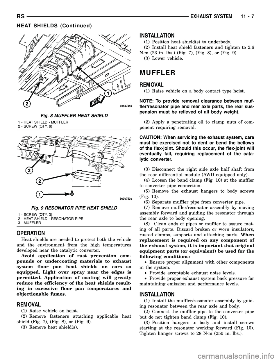
(2) Remove fasteners attaching applicable heat
shield (Fig. 7), (Fig. 8), or (Fig. 9).
(3) Remove heat shield(s).
INSTALLATION
(1) Position heat shield(s) to underbody.
(2) Install heat shield fasteners and tighten to 2.6
N´m (23 in. lbs.) (Fig. 7), (Fig. 8), or (Fig. 9).
(3) Lower vehicle.
MUFFLER
REMOVAL
(1) Raise vehicle on a body contact type hoist.
NOTE: To provide removal clearance between muf-
fler/resonator pipe and rear axle parts, the rear sus-
pension must be relieved of all body weight.
(2) Apply a penetrating oil to clamp nuts of com-
ponent requiring removal.
CAUTION: When servicing the exhaust system, care
must be exercised not to dent or bend the bellows
of the flex-joint. Should this occur, the flex-joint will
eventually fail, requiring replacement of the cata-
lytic converter.
(3) Disconnect the right side axle half shaft from
the rear differential module (AWD equipped only).
(4) Loosen the band clamp (Fig. 10) at the muffler
to converter pipe connection.
(5) Remove the exhaust hangers to body screws
(Fig. 10).
(6) Separate muffler pipe from converter pipe.
(7) Remove muffler/resonator assembly by moving
assembly forward and guiding the resonator through
the rear axle to body opening.
(8) Clean ends of pipes or muffler to assure mat-
ing of all parts. Discard broken or worn insulators,
rusted clamps, supports and attaching parts.When
replacement is required on any component of
the exhaust system, it is important that original
equipment parts (or equivalent) be used for the
following conditions:
²Ensure proper alignment with other components
in the system.
²Provide acceptable exhaust noise levels.
²Provide proper exhaust system back pressure for
maintaining emission and performance levels.
INSTALLATION
(1) Install the muffler/resonator assembly by guid-
ing resonator between the rear axle and body.
(2) Connect the muffler pipe to the converter pipe
but do not tighten band clamp (Fig. 10).
(3) Position hangers to body and install screws
starting at the resonator working forward (Fig. 10).
Tighten hanger screws to 28 N´m (250 in. lbs.).
Fig. 8 MUFFLER HEAT SHIELD
1 - HEAT SHIELD - MUFFLER
2 - SCREW (QTY. 6)
Fig. 9 RESONATOR PIPE HEAT SHIELD
1 - SCREW (QTY. 3)
2 - HEAT SHIELD - RESONATOR PIPE
3 - MUFFLER
RSEXHAUST SYSTEM11-7
HEAT SHIELDS (Continued)
Page 1526 of 2585
1 second. Therefore, battery voltage is not supplied to
the fuel pump, ignition coil, fuel injectors and heated
oxygen sensors.
ENGINE START-UP MODE
This is an OPEN LOOP mode. If the vehicle is in
park or neutral (automatic transaxles) or the clutch
pedal is depressed (manual transaxles) the ignition
switch energizes the starter relay when the engine is
not running. The following actions occur when the
starter motor is engaged.
²If the PCM receives the camshaft position sensor
and crankshaft position sensor signals, it energizes
the Auto Shutdown (ASD) relay and fuel pump relay.
If the PCM does not receive both signals within
approximately one second, it will not energize the
ASD relay and fuel pump relay. The ASD and fuel
pump relays supply battery voltage to the fuel pump,
fuel injectors, ignition coil, (EGR solenoid and PCV
heater if equipped) and heated oxygen sensors.
²The PCM energizes the injectors (on the 69É
degree falling edge) for a calculated pulse width until
it determines crankshaft position from the camshaft
position sensor and crankshaft position sensor sig-
nals. The PCM determines crankshaft position within
1 engine revolution.
²After determining crankshaft position, the PCM
begins energizing the injectors in sequence. It adjusts
injector pulse width and controls injector synchroni-
zation by turning the individual ground paths to the
injectors On and Off.
²When the engine idles within 64 RPM of its
target RPM, the PCM compares current MAP sensor
value with the atmospheric pressure value received
during the Ignition Switch On (zero RPM) mode.
Once the ASD and fuel pump relays have been
energized, the PCM determines injector pulse width
based on the following:
²MAP
²Engine RPM
²Battery voltage
²Engine coolant temperature
²Inlet/Intake air temperature (IAT)
²Throttle position
²The number of engine revolutions since cranking
was initiated
During Start-up the PCM maintains ignition tim-
ing at 9É BTDC.
ENGINE WARM-UP MODE
This is an OPEN LOOP mode. The following inputs
are received by the PCM:
²Manifold Absolute Pressure (MAP)
²Crankshaft position (engine speed)
²Engine coolant temperature
²Inlet/Intake air temperature (IAT)²Camshaft position
²Knock sensor
²Throttle position
²A/C switch status
²Battery voltage
²Vehicle speed
²Speed control
²O2 sensors
The PCM adjusts injector pulse width and controls
injector synchronization by turning the individual
ground paths to the injectors On and Off.
The PCM adjusts ignition timing and engine idle
speed. Engine idle speed is adjusted through the idle
air control motor.
CRUISE OR IDLE MODE
When the engine is at operating temperature this
is a CLOSED LOOP mode. During cruising or idle
the following inputs are received by the PCM:
²Manifold absolute pressure
²Crankshaft position (engine speed)
²Inlet/Intake air temperature
²Engine coolant temperature
²Camshaft position
²Knock sensor
²Throttle position
²Exhaust gas oxygen content (O2 sensors)
²A/C switch status
²Battery voltage
²Vehicle speed
The PCM adjusts injector pulse width and controls
injector synchronization by turning the individual
ground paths to the injectors On and Off.
The PCM adjusts engine idle speed and ignition
timing. The PCM adjusts the air/fuel ratio according
to the oxygen content in the exhaust gas (measured
by the upstream and downstream heated oxygen sen-
sor).
The PCM monitors for engine misfire. During
active misfire and depending on the severity, the
PCM either continuously illuminates or flashes the
malfunction indicator lamp (Check Engine light on
instrument panel). Also, the PCM stores an engine
misfire DTC in memory, if 2nd trip with fault.
The PCM performs several diagnostic routines.
They include:
²Oxygen sensor monitor
²Downstream heated oxygen sensor diagnostics
during open loop operation (except for shorted)
²Fuel system monitor
²EGR monitor (if equipped)
²Purge system monitor
²Catalyst efficiency monitor
²All inputs monitored for proper voltage range,
rationality.
RSFUEL INJECTION14-19
FUEL INJECTION (Continued)
Page 1535 of 2585

(3) Disconnect injector wiring connector from injec-
tor.
(4) Position fuel rail assembly so that the fuel
injectors are easily accessible (Fig. 13).
(5) Rotate injector and pull injector out of fuel rail.
The clip will stay on the injector.
(6) Check injector O-ring for damage. If O-ring is
damaged, it must be replaced. If injector is reused, a
protective cap must be installed on the injector tip to
prevent damage. Replace the injector clip if it is dam-
aged.
(7) Repeat for remaining injectors.
INSTALLATION
INSTALLATION - 2.4L
The fuel rail must be removed first. Refer to Fuel
Injector Rail Removal in this section.
(1) Before installing an injector the rubber O-ring
must be lubricated with a drop of clean engine oil to
aid in installation.
(2) Install injector clip by sliding open end into the
top slot of the injector. The edge of the receiver cup
will slide into the side slots of clip.
(3) Install injector top end into fuel rail receiver
cap. Be careful not to damage O-ring during installa-
tion (Fig. 14).
(4) Repeat steps for remaining injectors.
(5) Connect fuel injector wiring.
INSTALLATION - 3.3/3.8L
(1) Before installing an injector the rubber O-ring
must be lubricated with a drop of clean engine oil to
aid in installation.(2) Install injector clip by sliding open end into the
top slot of the injector. The edge of the receiver cup
will slide into the side slots of clip (Fig. 13).
(3) Install injector top end into fuel rail receiver
cap. Be careful not to damage O-ring during installa-
tion (Fig. 13).
(4) Repeat steps for remaining injectors.
(5) Install fuel rail, refer to Fuel Rail in the Fuel
Delivery section.
(6) Connect fuel injector wiring.
(7) Install the Intake Manifold, (Refer to 9 -
ENGINE/MANIFOLDS/INTAKE MANIFOLD -
INSTALLATION)
(8) Connect the negative battery cable.
FUEL PUMP RELAY
DESCRIPTION
The fuel pump relay is located in the PDC. The
inside top of the PDC cover has a label showing relay
and fuse location.
OPERATION
The fuel pump relay supplies battery voltage to the
fuel pump. A buss bar in the Power Distribution Cen-
ter (PDC) supplies voltage to the solenoid side and
contact side of the relay. The fuel pump relay power
circuit contains a fuse between the buss bar in the
PDC and the relay. The fuse is located in the PDC.
Refer to the Wiring Diagrams for circuit information.
The PCM controls the fuel pump relay by switch-
ing the ground path for the solenoid side of the relay
on and off. The PCM turns the ground path off when
the ignition switch is in the Off position. When the
ignition switch is in the On position, the PCM ener-
gizes the fuel pump. If the crankshaft position sensor
does not detect engine rotation, the PCM de-ener-
gizes the relay after approximately one second.
IDLE AIR CONTROL MOTOR
DESCRIPTION
The idle air control valve is mounted on the throt-
tle body. The PCM operates the idle air control valve
(Fig. 15) or (Fig. 16).
OPERATION
The PCM adjusts engine idle speed through the
idle air control valve to compensate for engine load,
coolant temperature or barometric pressure changes.
The throttle body has an air bypass passage that
provides air for the engine during closed throttle idle.
The idle air control valve regulates air flow through
the bypass passage.
Fig. 14 SERVICING FUEL INJECTOR TYPICAL
1 - FUEL INJECTOR
2 - LOCKING SLOT
3 - FUEL RAIL RECEIVER CUP
14 - 28 FUEL INJECTIONRS
FUEL INJECTOR (Continued)
Page 1536 of 2585

The PCM controls engine idle speed by adjusting
the position of the idle air control valve. The adjust-
ments are based on inputs the PCM receives. The
inputs are from the throttle position sensor, crank-
shaft position sensor, coolant temperature sensor,
MAP sensor, vehicle speed sensor and various switch
operations (brake, park/neutral, air conditioning).
When engine rpm is above idle speed, the IAC is
used for the following functions:
²Off-idle dashpot
²Deceleration air flow control²A/C compressor load control (also opens the pas-
sage slightly before the compressor is engaged so
that the engine rpm does not dip down when the
compressor engages)
Target Idle
Target idle is determined by the following inputs:
²Gear position
²ECT Sensor
²Battery voltage
²Ambient/Battery Temperature Sensor
²VSS
²TPS
²MAP Sensor
REMOVAL
When servicing throttle body components, always
reassemble components with new O-rings and seals
where applicable. If assembly of component is diffi-
cult, a light coat of engine oil may be applied to the
O-RINGS ONLY to aid assembly. Use care when
removing hoses to prevent damage to hose or hose
nipple.
(1) Disconnect negative cable from battery.
(2) Remove electrical connector from idle air con-
trol valve (Fig. 17).
(3) Remove idle air control valve mounting screw.
(4) Remove valve from throttle body. Ensure the
O-rings is removed with the valve.
INSTALLATION
When servicing throttle body components, always
reassemble components with new O-rings and seals
where applicable. If assembly of component is diffi-
cult,a light coat of engine oil may be applied to
Fig. 15 TPS/IAC 2.4L
1 - Idle Air Control Valve
2 - Throttle Position Sensor
Fig. 16 TPS/IAC 3.3/3.8L
1 - Idle Air Control Valve
2 - Throttle Position Sensor
Fig. 17 IDLE AIR CONTROL VALVE LOCATION
RSFUEL INJECTION14-29
IDLE AIR CONTROL MOTOR (Continued)