oil temperature CHRYSLER VOYAGER 2004 Manual Online
[x] Cancel search | Manufacturer: CHRYSLER, Model Year: 2004, Model line: VOYAGER, Model: CHRYSLER VOYAGER 2004Pages: 2585, PDF Size: 62.54 MB
Page 2010 of 2585
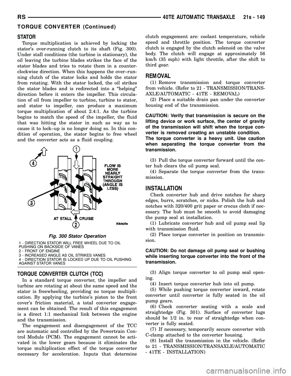
STATOR
Torque multiplication is achieved by locking the
stator's over-running clutch to its shaft (Fig. 300).
Under stall conditions (the turbine is stationary), the
oil leaving the turbine blades strikes the face of the
stator blades and tries to rotate them in a counter-
clockwise direction. When this happens the over±run-
ning clutch of the stator locks and holds the stator
from rotating. With the stator locked, the oil strikes
the stator blades and is redirected into a ªhelpingº
direction before it enters the impeller. This circula-
tion of oil from impeller to turbine, turbine to stator,
and stator to impeller, can produce a maximum
torque multiplication of about 2.4:1. As the turbine
begins to match the speed of the impeller, the fluid
that was hitting the stator in such as way as to
cause it to lock±up is no longer doing so. In this con-
dition of operation, the stator begins to free wheel
and the converter acts as a fluid coupling.
TORQUE CONVERTER CLUTCH (TCC)
In a standard torque converter, the impeller and
turbine are rotating at about the same speed and the
stator is freewheeling, providing no torque multipli-
cation. By applying the turbine's piston to the front
cover's friction material, a total converter engage-
ment can be obtained. The result of this engagement
is a direct 1:1 mechanical link between the engine
and the transmission. The engagement and disengagement of the TCC
are automatic and controlled by the Powertrain Con-
trol Module (PCM). The engagement cannot be acti-
vated in the lower gears because it eliminates the
torque multiplication effect of the torque converter
necessary for acceleration. Inputs that determine clutch engagement are: coolant temperature, vehicle
speed and throttle position. The torque converter
clutch is engaged by the clutch solenoid on the valve
body. The clutch will engage at approximately 56
km/h (35 mph) with light throttle, after the shift to
third gear.
REMOVAL
(1) Remove transmission and torque converter
from vehicle. (Refer to 21 - TRANSMISSION/TRANS-
AXLE/AUTOMATIC - 41TE - REMOVAL) (2) Place a suitable drain pan under the converter
housing end of the transmission.
CAUTION: Verify that transmission is secure on the
lifting device or work surface, the center of gravity
of the transmission will shift when the torque con-
verter is removed creating an unstable condition.
The torque converter is a heavy unit. Use caution
when separating the torque converter from the
transmission.
(3) Pull the torque converter forward until the cen-
ter hub clears the oil pump seal. (4) Separate the torque converter from the trans-
mission.
INSTALLATION
Check converter hub and drive notches for sharp
edges, burrs, scratches, or nicks. Polish the hub and
notches with 320/400 grit paper or crocus cloth if nec-
essary. The hub must be smooth to avoid damaging
the pump seal at installation. (1) Lubricate converter hub and oil pump seal lip
with transmission fluid. (2) Place torque converter in position on transmis-
sion.
CAUTION: Do not damage oil pump seal or bushing
while inserting torque converter into the front of the
transmission.
(3) Align torque converter to oil pump seal open-
ing. (4) Insert torque converter hub into oil pump.
(5) While pushing torque converter inward, rotate
converter until converter is fully seated in the oil
pump gears. (6) Check converter seating with a scale and
straightedge (Fig. 301). Surface of converter lugs
should be 1/2 in. to rear of straightedge when con-
verter is fully seated. (7) If necessary, temporarily secure converter with
C-clamp attached to the converter housing. (8) Install the transmission in the vehicle. (Refer
to 21 - TRANSMISSION/TRANSAXLE/AUTOMATIC
- 41TE - INSTALLATION)
Fig. 300 Stator Operation
1 - DIRECTION STATOR WILL FREE WHEEL DUE TO OIL
PUSHING ON BACKSIDE OF VANES
2 - FRONT OF ENGINE
3 - INCREASED ANGLE AS OIL STRIKES VANES
4 - DIRECTION STATOR IS LOCKED UP DUE TO OIL PUSHING
AGAINST STATOR VANES
RS 40TE AUTOMATIC TRANSAXLE21s - 149
TORQUE CONVERTER (Continued)
Page 2012 of 2585
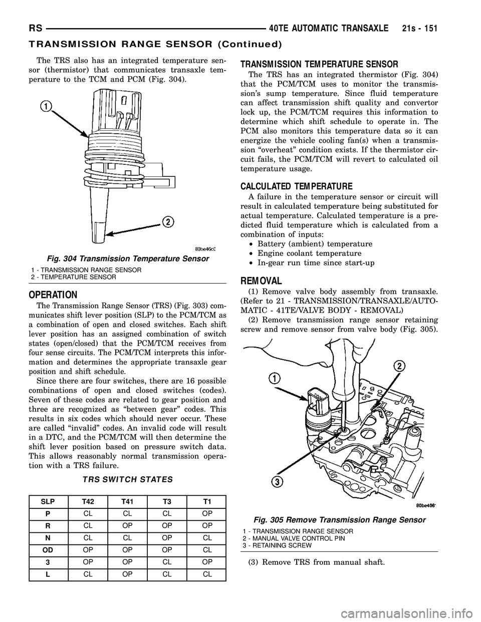
The TRS also has an integrated temperature sen-
sor (thermistor) that communicates transaxle tem-
perature to the TCM and PCM (Fig. 304).
OPERATION
The Transmission Range Sensor (TRS) (Fig. 303) com-
municates shift lever position (SLP) to the PCM/TCM as
a combination of open and closed switches. Each shift
lever position has an assigned combination of switch
states (open/closed) that the PCM/TCM receives from
four sense circuits. The PCM/TCM interprets this infor-
mation and determines the appropriate transaxle gear
position and shift schedule.
Since there are four switches, there are 16 possible
combinations of open and closed switches (codes).
Seven of these codes are related to gear position and
three are recognized as ªbetween gearº codes. This
results in six codes which should never occur. These
are called ªinvalidº codes. An invalid code will result
in a DTC, and the PCM/TCM will then determine the
shift lever position based on pressure switch data.
This allows reasonably normal transmission opera-
tion with a TRS failure.
TRS SWITCH STATES
SLP T42 T41 T3 T1
P CL CL CL OP
R CL OP OP OP
N CL CL OP CL
OD OP OP OP CL
3 OP OP CL OP
L CL OP CL CL
TRANSMISSION TEMPERATURE SENSOR
The TRS has an integrated thermistor (Fig. 304)
that the PCM/TCM uses to monitor the transmis-
sion's sump temperature. Since fluid temperature
can affect transmission shift quality and convertor
lock up, the PCM/TCM requires this information to
determine which shift schedule to operate in. The
PCM also monitors this temperature data so it can
energize the vehicle cooling fan(s) when a transmis-
sion ªoverheatº condition exists. If the thermistor cir-
cuit fails, the PCM/TCM will revert to calculated oil
temperature usage.
CALCULATED TEMPERATURE
A failure in the temperature sensor or circuit will
result in calculated temperature being substituted for
actual temperature. Calculated temperature is a pre-
dicted fluid temperature which is calculated from a
combination of inputs: ² Battery (ambient) temperature
² Engine coolant temperature
² In-gear run time since start-up
REMOVAL
(1) Remove valve body assembly from transaxle.
(Refer to 21 - TRANSMISSION/TRANSAXLE/AUTO-
MATIC - 41TE/VALVE BODY - REMOVAL) (2) Remove transmission range sensor retaining
screw and remove sensor from valve body (Fig. 305).
(3) Remove TRS from manual shaft.
Fig. 304 Transmission Temperature Sensor
1 - TRANSMISSION RANGE SENSOR
2 - TEMPERATURE SENSOR
Fig. 305 Remove Transmission Range Sensor
1 - TRANSMISSION RANGE SENSOR
2 - MANUAL VALVE CONTROL PIN
3 - RETAINING SCREW
RS 40TE AUTOMATIC TRANSAXLE21s - 151
TRANSMISSION RANGE SENSOR (Continued)
Page 2399 of 2585
²a rear window defogger on/off switch. A graphic
symbol shows when the defroster is on.
²a rotary knob for front fan speed selection can
override the automatic controls. LEDs surrounding
the knob show the current setting.
²a rotary knob for control of the rear system.
²a rotary knob for mode control can override the
automatic controls. LEDs surrounding the knob show
the current setting.
²computer logic which remembers the settings of
the controls when the ignition is turned off and
retains those settings after a restart. If the system is
off when the ignition is turned off it will be off when
the engine is restarted, etc.
²computer logic which provides variable air recir-
culation under high temperature and humidity condi-
tions. Because recirculation is generally accompanied
by increased fan noise, the proportion of recirculated
to outside air gradually approaches full recirculation
over a broad temperature range.
²computer logic which enables additional heat for
diesel equipped vehicles by using a supplemental
engine coolant heater.
REAR CONTROL PANEL
A rear control panel centrally mounted on the
headliner includes a VF digital display, a rocker con-
trol for temperature and rotary controls for adjust-
ment of mode and fan speed of the rear heat and air
conditioning unit by intermediate seat passengers.
OPERATION
OPERATION - HEATER AND AIR CONDITIONER
The heating and air conditioning systems pulls
outside (ambient) air through the cowl opening at the
base of the windshield and into the plenum chamber
above the heating, ventilation and air conditioning
(HVAC) housing, then through the evaporator coil.
Air flow can be directed either through or around the
heater core by adjusting the blend door with the tem-
perature control knob on the A/C-heater control
located on instrument panel. The air flow can then
be directed out from the panel, floor and defrost out-
lets in various combinations using the mode control
knob located on the A/C-heater control. Air flow
velocity can be adjusted with the blower speed selec-
tor located on the
NOTE: It is important to keep the air intake opening
clear of debris. Leaf particles and other debris that
is small enough to pass through the cowl opening
screen can accumulate within the HVAC housing.
The closed, warm, damp and dark environment cre-
ated within the housing is ideal for the growth of
certain molds, mildews and other fungi. Any accu-mulation of decaying plant matter provides an addi-
tional food source for fungal spores, which enter
the housing with the fresh intake-air. Excess debris,
as well as objectionable odors created by decaying
plant matter and growing fungi can be discharged
into the passenger compartment during heater-A/C
operation if the air intake opening is not kept clear
of debris.
The heater and air conditioning system is a blend-
air type system. In a blend-air system, a blend door
controls the amount of conditioned air that is allowed
to flow through, or around, the heater core. The tem-
perature control knob determines the discharge air
temperature by actuating an electric motor, which
operates the blend door. This allows an almost imme-
diate control of the output air temperature of the sys-
tem.
On all models, the outside air intake can be shut
off by pressing the Recirculation button on the A/C-
heater control. This will operate a electric actuated
recirculation air door that closes off the outside fresh
air intake and recirculates the air that is already
inside the vehicle.
The air conditioning compressor can be engaged in
any mode by pressing the snowflake, A/C on/off but-
ton. It can also be engaged by placing the mode con-
trol in the mix to defrost positions. This will remove
heat and humidity from the air before it is directed
through or around the heater core. The mode control
knob on the A/C-heater control is used to also direct
the conditioned air to the selected system outlets.
The mode control switch uses an electric motor to
control the mode doors.OPERATION - SINGLE ZONE
²The temperature control knob enables continu-
ously variable proportioning of the conditioned air.
²The mode control knob enables continuously
variable proportioning of air flow between modes and
has detents adjacent to each icon.
²The blower control provides four separate speeds
and an Off position.
²When the heater-A/C system is off, the HVAC
computer closes the recirculation door to prevent out-
side air from entering the passenger compartment.
²Interior air may be recirculated to speed up
heating or cooling in all modes except defrost and
mix by pressing the Recirculate button on the A/C-
heater control.
²To reduce humidity for rapid defogging, the A/C
compressor runs automatically in modes from ªmixº
to full defrost when outside temperatures are above
freezing.
²Air conditioning is available in any mode by
pressing the snowflake, A/C on/off button.
24 - 4 HEATING & AIR CONDITIONINGRS
HEATING & AIR CONDITIONING (Continued)
Page 2402 of 2585
required. If the test is failed, the snowflake icon and
the DELAY text will continue to blink across ignition
cycles until the vehicle has been driven for greater
than 1.6 km (8 miles).
DIAGNOSIS AND TESTING - A/C
PERFORMANCE TEST
The A/C system is designed to remove heat and
humidity from the air entering the passenger com-
partment. The evaporator, located in the HVAC hous-
ing, is cooled to temperatures near the freezing point.
As warm damp air passes over the fins in the A/C
evaporator, moisture in the air condenses to water,
dehumidifying the air. Condensation on the evapora-
tor fins reduces the evaporators ability to absorb
heat. During periods of high heat and humidity, an
A/C system will be less effective. With the instru-
ment control set to recirculation mode, only air from
the passenger compartment passes through the A/C
evaporator. As the passenger compartment air dehu-
midifies, A/C performance levels rise.
Humidity has an important bearing on the temper-
ature of the air delivered to the interior of the vehi-
cle. It is important to understand the effect that
humidity has on the performance of the A/C system.
When humidity is high, the A/C evaporator has to
perform a double duty. It must lower the air temper-
ature, and it must lower the temperature of the
moisture in the air that condenses on the evaporator
fins. Condensing the moisture in the air transfers
heat energy into the evaporator fins and tubing. This
reduces the amount of heat the A/C evaporator can
absorb from the air. High humidity greatly reduces
the ability of the A/C evaporator to lower the temper-
ature of the air.
However, evaporator capacity used to reduce the
amount of moisture in the air is not wasted. Wring-
ing some of the moisture out of the air entering the
vehicle adds to the comfort of the passengers.
Although, an owner may expect too much from their
A/C system on humid days. A performance test is the
best way to determine whether the system is per-
forming up to design standards. This test also pro-
vides valuable clues as to the possible cause of
trouble with the A/C system. The ambient air tem-perature in the location where the vehicle will be
tested must be a minimum of 21É C (70É F) for this
test.
PERFORMANCE TEST PROCEDURE
WARNING: REFER TO THE APPLICABLE WARN-
INGS AND CAUTIONS FOR THIS SYSTEM BEFORE
PERFORMING THE FOLLOWING OPERATION (Refer
to 24 - HEATING & AIR CONDITIONING/PLUMBING -
FRONT - WARNING - A/C PLUMBING) and (Refer to
24 - HEATING & AIR CONDITIONING/PLUMBING -
FRONT - CAUTION - A/C PLUMBING).
NOTE: When connecting the service equipment
coupling to the line fitting, verify that the valve of
the coupling is fully closed. This will reduce the
amount of effort required to make the connection.
(1) Connect a tachometer and a manifold gauge
set.
(2) Set the mode control to the Recirculation Mode
position, the temperature control to the full cool posi-
tion and the blower to the highest speed position.
(3) Start the engine and hold at 1,000 rpm with
the A/C compressor clutch engaged.
(4) The engine should be warmed up to operating
temperature with the doors closed and windows
open.
(5) Insert a thermometer in the driver's side center
panel A/C-heater outlet and operate the engine for
five minutes.
(6) If the compressor clutch does not engage, pro-
ceed with diagnosis of the compressor clutch coil.
(Refer to 24 - HEATING & AIR CONDITIONING/
CONTROLS - FRONT/COMPRESSOR CLUTCH
COIL - DIAGNOSIS AND TESTING).
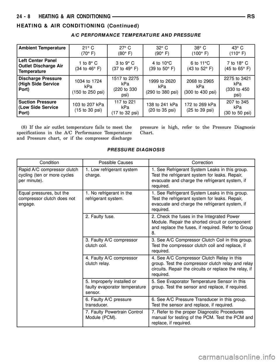
(7) With the A/C compressor clutch engaged, com-
pare the air temperature at the center panel outlet
and the compressor discharge pressure to the A/C
Performance Temperature and Pressure chart. The
compressor clutch may cycle, depending upon the
ambient temperature and humidity. If the clutch
cycles, use the readings obtained before the clutch
disengaged.
RSHEATING & AIR CONDITIONING24-7
HEATING & AIR CONDITIONING (Continued)
Page 2403 of 2585
A/C PERFORMANCE TEMPERATURE AND PRESSURE
Ambient Temperature21É C
(70É F)27É C
(80É F)32É C
(90É F)38É C
(100É F)43É C
(110É F)
Left Center Panel
Outlet Discharge Air
Temperature1to8ÉC
(34 to 46É F)3to9ÉC
(37 to 49É F)4 to 10ÉC
(39 to 50É F)6to11ÉC
(43 to 52É F)7 to 18É C
(45 to 65É F)
Discharge Pressure
(High Side Service
Port)1034 to 1724
kPa
(150 to 250 psi)1517 to 2275
kPa
(220 to 330
psi)1999 to 2620
kPa
(290 to 380 psi)2068 to 2965
kPa
(300 to 430 psi)2275 to 3421
kPa
(330 to 450
psi)
Suction Pressure
(Low Side Service
Port)103 to 207 kPa
(15 to 30 psi)117to221
kPa
(17 to 32 psi)138 to 241 kPa
(20 to 35 psi)172 to 269 kPa
(25 to 39 psi)207 to 345
kPa
(30 to 50 psi)
(8) If the air outlet temperature fails to meet the
specifications in the A/C Performance Temperature
and Pressure chart, or if the compressor dischargepressure is high, refer to the Pressure Diagnosis
Chart.
PRESSURE DIAGNOSIS
Condition Possible Causes Correction
Rapid A/C compressor clutch
cycling (ten or more cycles
per minute).1. Low refrigerant system
charge.1. See Refrigerant System Leaks in this group.
Test the refrigerant system for leaks. Repair,
evacuate and charge the refrigerant system, if
required.
Equal pressures, but the
compressor clutch does not
engage.1. No refrigerant in the
refrigerant system.1. See Refrigerant System Leaks in this group.
Test the refrigerant system for leaks. Repair,
evacuate and charge the refrigerant system, if
required.
2. Faulty fuse. 2. Check the fuses in the Integrated Power
Module. Repair the shorted circuit or component
and replace the fuses, if required. Refer to Group
8.
3. Faulty A/C compressor
clutch coil.3. See A/C Compressor Clutch Coil in this group.
Test the compressor clutch coil and replace, if
required.
4. Faulty A/C compressor
clutch relay.4. See A/C Compressor Clutch Relay in this
group. Test the compressor clutch relay and relay
circuits. Repair the circuits or replace the relay, if
required.
5. Improperly installed or
faulty evaporator temperature
sensor.5. See Evaporator Temperature Sensor in this
group. Test the sensor and replace, if required.
6. Faulty A/C pressure
transducer.6. See A/C Pressure Transducer in this group.
Test the sensor and replace, if required.
7. Faulty Powertrain Control
Module (PCM).7. Refer to the proper Diagnostic Procedures
manual for testing of the PCM. Test the PCM and
replace, if required.
24 - 8 HEATING & AIR CONDITIONINGRS
HEATING & AIR CONDITIONING (Continued)
Page 2404 of 2585

Condition Possible Causes Correction
Normal pressures, but A/C
Performance Test air
temperatures at center panel
outlet are too high.1. Excessive refrigerant oil in
system.1. See Refrigerant Oil Level in this group.
Recover the refrigerant from the refrigerant
system and inspect the refrigerant oil content.
Restore the refrigerant oil to the proper level, if
required.
2. Blend door actuator
improperly installed or faulty.2. See Blend Door Actuator in this group. Inspect
the actuator for proper operation and replace, if
required.
3. Blend door inoperative or
sealing improperly.3. See HVAC Housing in this group. Inspect the
blend door for proper operation and sealing.
Repair if required.
The low side pressure is
normal or slightly low, and the
high side pressure is too low.1. Low refrigerant system
charge.1. See Refrigerant System Leaks in this group.
Test the refrigerant system for leaks. Repair,
evacuate and charge the refrigerant system, if
required.
2. Refrigerant flow through
the A/C evaporator is
restricted.2. See A/C Evaporator in this group. Replace the
restricted A/C evaporator, if required.
3. Faulty A/C compressor. 3. See A/C Compressor in this group. Replace
the compressor, if required.
The low side pressure is
normal or slightly high, and
the high side pressure is too
high.1. A/C condenser air flow
restricted.1. Check the A/C condenser for damaged fins,
foreign objects obstructing air flow through the
condenser fins, and missing or improperly
installed air seals. Clean, repair, or replace
components as required.
2. Refrigerant flow through
the receiver/drier is
restricted.2. See Receiver/Drier in this group. Replace the
restricted receiver/drier, if required.
3. Inoperative radiator
cooling fan.3. Test the radiator cooling fan and replace, if
required. Refer to Group 7.
4. Refrigerant system
overcharged.4. See Refrigerant System Charge in this group.
Recover the refrigerant from the refrigerant
system. Charge the refrigerant system to the
proper level, if required.
5. Air in the refrigerant
system.5. See Refrigerant System Leaks in this group.
Test the refrigerant system for leaks. Repair,
evacuate and charge the refrigerant system, if
required.
6. Engine overheating. 6. Test the engine cooling system and repair, if
required. Refer to Group 7.
The low side pressure is too
high, and the high side
pressure is too low.1. Accessory drive belt
slipping.1. Inspect the accessory drive belt condition and
tension. Tighten or replace the accessory drive
belt, if required. Refer to Group 7.
2. Faulty A/C expansion
valve.2. See A/C Expansion Valve in this group.
Replace the valve, if required.
3. Faulty A/C compressor. 3. See A/C Compressor in this group. Replace
the compressor, if required.
RSHEATING & AIR CONDITIONING24-9
HEATING & AIR CONDITIONING (Continued)
Page 2406 of 2585
MECHANICAL PROBLEMS
Possible causes of insufficient heat due to mechan-
ical problems are as follows:
²Obstructed cowl air intake.
²Obstructed heater system outlets.
²Blend door not functioning properly.
TEMPERATURE CONTROL
If the heater outlet air temperature cannot be
adjusted with the temperature control knob on the
A/C-heater control panel, the following could require
service:
²Blend door binding.²Faulty blend door actuator.
²Faulty A/C-heater control.
²Faulty related wiring harness or connectors.
²Improper engine coolant temperature.
SPECIFICATIONS
A/C SYSTEM
The R-134a refrigerant system charge capacity for
this vehicle can be found on the underhood Specifica-
tion Label.
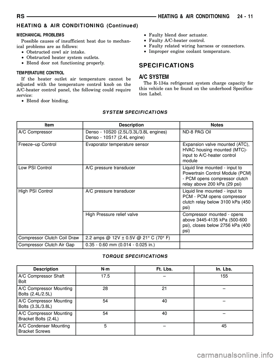
SYSTEM SPECIFICATIONS
Item Description Notes
A/C Compressor Denso - 10S20 (2.5L/3.3L/3.8L engines)
Denso - 10S17 (2.4L engine)ND-8 PAG Oil
Freeze±up Control Evaporator temperature sensor Expansion valve mounted (ATC),
HVAC housing mounted (MTC)-
input to A/C-heater control
module
Low PSI Control A/C pressure transducer Liquid line mounted - input to
Powertrain Control Module (PCM)
- PCM opens compressor clutch
relay above 200 kPa (29 psi)
High PSI Control A/C pressure transducer Liquid line mounted - input to
PCM - PCM opens compressor
clutch relay below 3100 kPa (450
psi)
High Pressure relief valve Compressor mounted - opens
above 3445-4135 kPa (500-600
psi), closes below 2756 kPa (400
psi)
Compressor Clutch Coil Draw 2.2 amps @ 12V 0.5V @ 21É C (70É F)
Compressor Clutch Air Gap 0.35 - 0.60 mm (0.014 - 0.025 in.)
TORQUE SPECIFICATIONS
Description N´m Ft. Lbs. In. Lbs.
A/C Compressor Shaft
Bolt17.5 ± 155
A/C Compressor Mounting
Bolts (2.4L/2.5L)28 21 ±
A/C Compressor Mounting
Bolts (3.3L/3.8L)54 40 ±
A/C Compressor Mounting
Bracket Bolts (2.4L)54 40 ±
A/C Condenser Mounting
Bracket Screws5±45
RSHEATING & AIR CONDITIONING24-11
HEATING & AIR CONDITIONING (Continued)
Page 2409 of 2585
CONTROLS - FRONT
TABLE OF CONTENTS
page page
A/C COMPRESSOR CLUTCH/COIL
DESCRIPTION.........................15
OPERATION...........................15
DIAGNOSIS AND TESTING - A/C
COMPRESSOR CLUTCH COIL...........15
REMOVAL.............................16
INSPECTION..........................17
INSTALLATION.........................17
A/C COMPRESSOR CLUTCH RELAY
DESCRIPTION.........................19
OPERATION...........................19
REMOVAL.............................20
INSTALLATION.........................20
A/C HEATER CONTROL
DESCRIPTION.........................20
STANDARD PROCEDURE - A/C-HEATER
CONTROL CALIBRATION...............20
REMOVAL.............................21
INSTALLATION.........................21
A/C PRESSURE TRANSDUCER
DESCRIPTION.........................21
OPERATION...........................21
DIAGNOSIS AND TESTING - A/C PRESSURE
TRANSDUCER.......................22
REMOVAL.............................22
INSTALLATION.........................22
BLEND DOOR ACTUATOR
DESCRIPTION.........................23
OPERATION...........................23
REMOVAL.............................23
INSTALLATION.........................23
BLOWER MOTOR RELAY
DESCRIPTION.........................24
OPERATION...........................24
REMOVAL.............................25
INSTALLATION.........................25
BLOWER MOTOR RESISTOR BLOCK
DESCRIPTION.........................26OPERATION...........................26
DIAGNOSIS AND TESTING - BLOWER
MOTOR RESISTOR BLOCK..............26
REMOVAL.............................26
INSTALLATION.........................27
EVAPORATOR TEMPERATURE SENSOR
DESCRIPTION.........................27
OPERATION...........................28
REMOVAL
REMOVAL - AUTOMATIC TEMPERATURE
CONTROL (ATC)......................28
REMOVAL - MANUAL TEMPERATURE
CONTROL (MTC)......................29
INSTALLATION
INSTALLATION - AUTOMATIC
TEMPERATURE CONTROL (ATC).........29
INSTALLATION - MANUAL TEMPERATURE
CONTROL (MTC)......................29
INFRARED TEMPERATURE SENSOR
DESCRIPTION.........................29
OPERATION...........................29
MODE DOOR ACTUATOR
DESCRIPTION.........................30
OPERATION...........................30
REMOVAL.............................30
INSTALLATION.........................31
POWER MODULE - BLOWER MOTOR
DESCRIPTION.........................31
OPERATION...........................31
REMOVAL.............................31
INSTALLATION.........................32
RECIRCULATION DOOR ACTUATOR
DESCRIPTION.........................32
OPERATION...........................32
REMOVAL.............................33
INSTALLATION.........................33
24 - 14 CONTROLS - FRONTRS
Page 2410 of 2585

A/C COMPRESSOR CLUTCH/
COIL
DESCRIPTION
The A/C compressor clutch assembly consists of a
stationary electromagnetic A/C clutch field coil with a
zener diode, a pulley bearing and pulley assembly,
and a clutch plate (Fig. 1). A/C clutch field coil and
the pulley bearing and pulley assembly are each
retained on the nose of the compressor front housing
with snap rings. The clutch plate is keyed or splined
to the compressor shaft, and secured with a nut or
bolt (depending on application). These components
provide the means to engage and disengage the com-
pressor from the engine serpentine accessory drive
belt.
The A/C compressor clutch and coil are available
for separate service replacement. The clutch coil
zener diode is integral to the clutch coil pigtail wire
and connector and, if faulty or damaged, the clutch
electromagnetic coil must be replaced.
OPERATION
The compressor clutch components provide the
means to engage and disengage the compressor from
the engine serpentine accessory drive belt. When the
clutch coil is energized, it magnetically draws the
clutch plate into contact with the clutch pulley and
drives the compressor shaft. When the coil is not
energized, the pulley freewheels on the clutch hub
bearing, which is part of the pulley.
A zener diode is connected in parallel with the
clutch electromagnetic coil. This diode controls the
dissipation of voltage induced into the coil windingsby the collapsing of the electromagnetic fields that
occurs when the compressor clutch is disengaged.
The zener diode dissipates this induced voltage by
regulating a current path to ground. This arrange-
ment serves to protect other circuits and components
from potentially damaging voltage spikes in the vehi-
cle electrical system that might occur if the voltage
induced in the clutch coil windings could not be dis-
sipated.
The compressor clutch engagement is controlled by
several components: the heater-A/C controls in the
passenger compartment, the A/C pressure transducer
on the liquid line, the evaporator temperature sensor
on the expansion valve for automatic temperature
control (ATC) system or on the HVAC housing for
manual temperature control (MTC) system, the Pow-
ertrain Control Module (PCM) in the engine compart-
ment, and the compressor clutch relay in the
Integrated Power Module (IPM). The PCM may delay
compressor clutch engagement for up to thirty sec-
onds (Refer to 8 - ELECTRICAL/ELECTRONIC
CONTROL MODULES/POWERTRAIN CONTROL
MODULE - DESCRIPTION - PCM OPERATION).
DIAGNOSIS AND TESTING - A/C COMPRESSOR
CLUTCH COIL
The air conditioning compressor clutch coil electri-
cal circuit is controlled by the powertrain control
module (PCM) through the A/C compressor clutch
relay, which is located in the integrated power mod-
ule (IPM) in the engine compartment. Begin testing
of a suspected compressor clutch coil problem by per-
forming the preliminary checks.
PRELIMINARY CHECKS
(1) If the compressor clutch will not engage, verify
the refrigerant charge level (Refer to 24 - HEATING
& AIR CONDITIONING/PLUMBING - FRONT/RE-
FRIGERANT - DIAGNOSIS AND TESTING -
REFRIGERANT CHARGE LEVEL). If the refriger-
ant charge level is OK, go to Step 2. If the refriger-
ant charge level is not OK, adjust the refrigerant
charge as required.
(2) If the A/C compressor clutch still will not
engage, disconnect the wire harness connector for the
A/C pressure transducer and check for battery cur-
rent at the connector with the engine running and
the A/C-heater control set to the A/C mode. If OK, go
to TESTS. If not OK, refer to Body Diagnostic Proce-
dures to perform further diagnosis.
TESTS
(1) Verify the battery state of charge (Refer to 8 -
ELECTRICAL/BATTERY SYSTEM/BATTERY -
DIAGNOSIS AND TESTING).
Fig. 1 Compressor Clutch - Typical
1 - CLUTCH PLATE
2 - SHAFT KEY (SOME MODELS)
3 - PULLEY AND BEARING
4 - CLUTCH COIL
5 - CLUTCH SHIMS
6 - SNAP RING
7 - SNAP RING
RSCONTROLS - FRONT24-15
Page 2411 of 2585

(2) Connect an ammeter (0 to 10 ampere scale
selected) in series with the clutch coil feed terminal.
Connect a voltmeter (0 to 20 volt scale selected) to
measure voltage across the battery and the clutch
coil.
(3) With the heater-A/C control in the A/C mode
and the blower at low speed, start the engine and
allow it to run at a normal idle speed.
(4) The compressor clutch should engage immedi-
ately, and the clutch coil voltage should be within
two volts of the battery voltage. If the coil voltage is
not within two volts of battery voltage, test the
clutch coil feed circuit for excessive voltage drop. If
the compressor clutch does not engage, refer to Body
Diagnostic Procedures to perform further diagnosis.
(5) Refer to the A/C Clutch Coil Current Draw
chart for the acceptable A/C clutch coil current draw
specifications. Specifications apply for a work area
temperature of 21É C (70É F). If voltage is more than
12.5 volts, add electrical loads by turning on electri-
cal accessories until voltage reads below 12.5 volts.
(a) If the compressor clutch coil current reading
is zero, the coil is open and must be replaced.
(b) If the compressor clutch coil current reading
is four amperes or more, the coil is shorted and
must be replaced.
A/C CLUTCH COIL CURRENT DRAW
Compressor Current Draw
Nippondenso - 10S20
(2.5L/3.3L/3.8L engines)
Nippondenso - 10S17
(2.4L engine)2.2 amps @ 11.5 - 12.5
volts
REMOVAL
NOTE: The compressor clutch can be serviced in
the vehicle. The refrigerant system can remain fully-
charged during compressor clutch, pulley, or coil
replacement.
(1) Disconnect and isolate the battery negative
cable.
(2) Remove the serpentine drive belt (Refer to 7 -
COOLING/ACCESSORY DRIVE/DRIVE BELTS -
2.4L - REMOVAL) or (Refer to 7 - COOLING/ACCES-
SORY DRIVE/DRIVE BELTS - 3.3/3.8L -
REMOVAL).
(3) Raise and support the vehicle.
(4) Disconnect the engine wire harness connector
for the compressor clutch coil from the clutch coil pig-
tail wire connector on the top of the compressor.
(5) On models with the 3.3L and 3.8L engines, dis-
engage the retainer on the engine wire harness com-
pressor clutch coil take out from the bracket on the
top of the compressor.(6) On models with the 2.4L and 2.5L engines,
remove all of the compressor mounting bolts except
the upper left (rear of the compressor), which should
only be loosened. Allow the front (pulley end) of the
compressor to tilt downward far enough to access the
clutch for removal, then tighten the loosened upper
left compressor mounting bolt.
(7) On models with the 3.3L and 3.8L engines,
remove the two bolts and two nuts that secure the
compressor to the engine. Disengage the mounting
ear at the front of the compressor from the stud on
the engine, allow the front (pulley end) of the com-
pressor to tilt downward far enough to access the
clutch for removal, then reinstall and tighten the
upper left compressor mounting bolt.
(8) Remove the compressor shaft bolt (Fig. 2). A
band-type oil filter wrench or a strap wrench may be
used to secure the clutch during bolt removal.
(9) Tap the clutch plate lightly with a plastic mal-
let to release it from the splines on the compressor
shaft. Remove the clutch plate and shim(s) from the
compressor shaft (Fig. 3).
NOTE: Use care not to lose any of the shim(s).
CAUTION: Do not pry between the clutch plate unit
and the pulley to remove the clutch plate from the
compressor shaft as this may damage the clutch
plate.
Fig. 2 Compressor Shaft Bolt and Clutch Plate
1 - COMPRESSOR SHAFT BOLT
2 - COMPRESSOR CLUTCH PLATE
24 - 16 CONTROLS - FRONTRS
A/C COMPRESSOR CLUTCH/COIL (Continued)