wheel bolts CHRYSLER VOYAGER 2004 Repair Manual
[x] Cancel search | Manufacturer: CHRYSLER, Model Year: 2004, Model line: VOYAGER, Model: CHRYSLER VOYAGER 2004Pages: 2585, PDF Size: 62.54 MB
Page 261 of 2585
Replacebothdisc brake shoes (inboard and out-
board) on each caliper. It is necessary to replace the
shoes on the opposite side of the vehicle as well as
the shoes failing inspection. If the brake shoe assemblies do not require
replacement, be sure to reinstall the brake shoes in
the original position they were removed from.
INSTALLATION - REAR DISC BRAKE SHOES
(1) Completely retract caliper piston back into pis-
ton bore of caliper assembly. (2) Lubricate both adapter abutments where the
shoes contact with a liberal amount of Mopar tMul-
tipurpose Lubricant, or equivalent. (3) If removed, install the brake rotor on the hub,
making sure it is squarely seated on the face of the
hub. (4) Install the inboard brake shoe into the caliper
piston by firmly pressing it into the piston bore using
your thumbs. Be sure inboard brake shoe is posi-
tioned squarely against the face of the caliper piston.
NOTE: The outboard shoes are different left to
right. They can be identified by a L or R stamped on
the clip.
(5) Install the outboard brake shoe on the disc
brake caliper. Be sure the outboard shoe is positioned
squarely against the outboard fingers of the caliper.
CAUTION: Use care when installing the caliper
assembly onto the adapter, so the caliper guide pin
bushings do not get damaged by the mounting
bosses.
(6) Carefully lower caliper and brake shoes over
rotor and onto adapter, reversing the removal proce-
dure (Fig. 15).
CAUTION: When installing the caliper guide pin
bolts extreme caution should be taken not to
crossthread the guide pin bolts.
(7) Install the caliper guide pin bolts. Tighten the
guide pin bolts to a torque of 35 N´m (26 ft. lbs.). (8) Install the wheel and tire assembly. Tighten
the wheel mounting nuts in proper sequence until all
nuts are torqued to half specification. Then repeat
the tightening sequence to the full specified torque of
135 N´m (100 ft. lbs.). (9) Lower vehicle.
CAUTION: Before moving vehicle, pump the brake
pedal several times to insure the vehicle has a firm
brake pedal to adequately stop the vehicle. (10) Pump brake pedal several times to set brake
shoes to rotors. (11) Check fluid level in reservoir.
(12) Road test the vehicle and make several stops
to wear off any foreign material on the brakes and to
seat the brake shoe linings.
BRAKE PADS/SHOES - REAR
DRUM
REMOVAL - REAR DRUM BRAKE SHOES
(1) Raise vehicle. (Refer to LUBRICATION &
MAINTENANCE/HOISTING - STANDARD PROCE-
DURE). (2) Remove the rear wheel and tire assemblies
from the vehicle. (3) Remove rear brake drum to hub retaining clips
(if equipped), then remove rear brake drums. (Refer
to 5 - BRAKES/HYDRAULIC/MECHANICAL/DRUM
- REMOVAL)
NOTE: When creating slack in the park brake cables
by locking out the automatic adjuster, (Fig. 18) be
sure that the park brake pedal is in the released
(most upward) position.
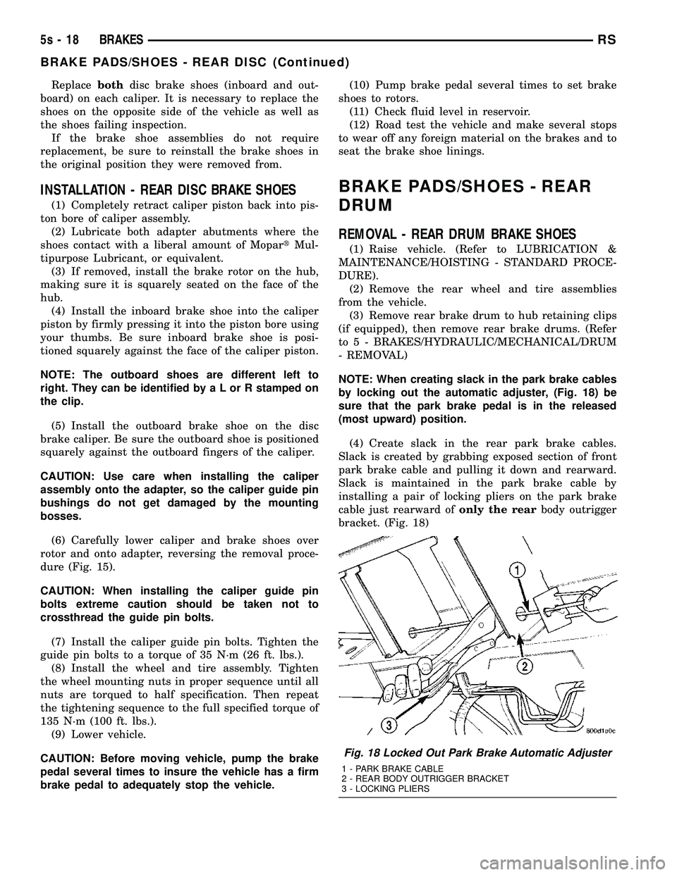
(4) Create slack in the rear park brake cables.
Slack is created by grabbing exposed section of front
park brake cable and pulling it down and rearward.
Slack is maintained in the park brake cable by
installing a pair of locking pliers on the park brake
cable just rearward of only the rearbody outrigger
bracket. (Fig. 18)
Fig. 18 Locked Out Park Brake Automatic Adjuster
1 - PARK BRAKE CABLE
2 - REAR BODY OUTRIGGER BRACKET
3 - LOCKING PLIERS
5s - 18 BRAKESRS
BRAKE PADS/SHOES - REAR DISC (Continued)
Page 266 of 2585
DISC BRAKE CALIPER -
FRONT
REMOVAL
REMOVAL - FRONT DISC BRAKE CALIPER
(CONTINENTAL TEVES BRAKES)
(1) Depress the brake pedal past its first inch of
travel and hold it in this position using a brake pedal
depressor (holding) tool. This is done to isolate the
master cylinder from the brake hydraulic system dis-
allowing the brake fluid to completely drain out of
the brake fluid reservoir. (2) Raise the vehicle. (Refer to LUBRICATION &
MAINTENANCE/HOISTING - STANDARD PROCE-
DURE). (3) Remove front wheel and tire assembly.
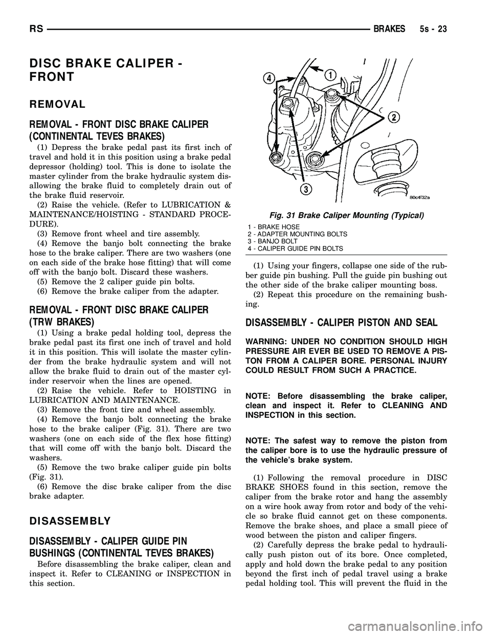
(4) Remove the banjo bolt connecting the brake
hose to the brake caliper. There are two washers (one
on each side of the brake hose fitting) that will come
off with the banjo bolt. Discard these washers. (5) Remove the 2 caliper guide pin bolts.
(6) Remove the brake caliper from the adapter.
REMOVAL - FRONT DISC BRAKE CALIPER
(TRW BRAKES)
(1) Using a brake pedal holding tool, depress the
brake pedal past its first one inch of travel and hold
it in this position. This will isolate the master cylin-
der from the brake hydraulic system and will not
allow the brake fluid to drain out of the master cyl-
inder reservoir when the lines are opened. (2) Raise the vehicle. Refer to HOISTING in
LUBRICATION AND MAINTENANCE. (3) Remove the front tire and wheel assembly.
(4) Remove the banjo bolt connecting the brake
hose to the brake caliper (Fig. 31). There are two
washers (one on each side of the flex hose fitting)
that will come off with the banjo bolt. Discard the
washers. (5) Remove the two brake caliper guide pin bolts
(Fig. 31). (6) Remove the disc brake caliper from the disc
brake adapter.
DISASSEMBLY
DISASSEMBLY - CALIPER GUIDE PIN
BUSHINGS (CONTINENTAL TEVES BRAKES)
Before disassembling the brake caliper, clean and
inspect it. Refer to CLEANING or INSPECTION in
this section. (1) Using your fingers, collapse one side of the rub-
ber guide pin bushing. Pull the guide pin bushing out
the other side of the brake caliper mounting boss. (2) Repeat this procedure on the remaining bush-
ing.
DISASSEMBLY - CALIPER PISTON AND SEAL
WARNING: UNDER NO CONDITION SHOULD HIGH
PRESSURE AIR EVER BE USED TO REMOVE A PIS-
TON FROM A CALIPER BORE. PERSONAL INJURY
COULD RESULT FROM SUCH A PRACTICE.
NOTE: Before disassembling the brake caliper,
clean and inspect it. Refer to CLEANING AND
INSPECTION in this section.
NOTE: The safest way to remove the piston from
the caliper bore is to use the hydraulic pressure of
the vehicle's brake system.
(1) Following the removal procedure in DISC
BRAKE SHOES found in this section, remove the
caliper from the brake rotor and hang the assembly
on a wire hook away from rotor and body of the vehi-
cle so brake fluid cannot get on these components.
Remove the brake shoes, and place a small piece of
wood between the piston and caliper fingers. (2) Carefully depress the brake pedal to hydrauli-
cally push piston out of its bore. Once completed,
apply and hold down the brake pedal to any position
beyond the first inch of pedal travel using a brake
pedal holding tool. This will prevent the fluid in the
Fig. 31 Brake Caliper Mounting (Typical)
1 - BRAKE HOSE
2 - ADAPTER MOUNTING BOLTS
3 - BANJO BOLT
4 - CALIPER GUIDE PIN BOLTS
RS BRAKES5s-23
Page 269 of 2585

INSTALLATION
INSTALLATION - FRONT DISC BRAKE CALIPER
(CONTINENTAL TEVES BRAKES)
CAUTION: TRW and Continental Teves brake cali-
pers are not interchangeable. Each caliper is specif-
ically designed for the unique brake system. If
calipers are interchanged, improper performance,
noise and increased stopping distance can occur.
(Refer to 5 - BRAKES/HYDRAULIC/MECHANICAL -
DESCRIPTION)
(1) Completely retract the caliper piston back into
piston bore of the caliper. Use a C-clamp to retract
the piston if necessary. Place a wood block over the
piston before installing the C-clamp to avoid damag-
ing the piston.
CAUTION: Use care when installing the brake cali-
per assembly onto the steering knuckle, so that the
seals on the caliper guide pin bushings do not get
damaged by the steering knuckle bosses.
(2) Carefully position the brake caliper and shoes
over the brake rotor and adapter. (3) Install the caliper guide pin bolts and tighten
to a torque of 35 N´m (26 ft. lbs.). Extreme caution
should be taken not to cross thread the caliper
guide pin bolts. (4) Install the anti-rattle clip on the outboard side
of the caliper. Start the clip into the holes on the cal-
iper, then stretch the clip legs past the abutments on
the caliper adapter.
CAUTION: When connecting the brake hose to the
caliper, install new brake hose to caliper special
copper washers.
(5) Install the brake hose on the caliper. To do
this, first place one NEW special fitting washer on
each side of the hose fitting, then slide the banjo bolt
through the fitting. Next, thread the banjo bolt into
the threaded port on the rear of the brake caliper.
Tighten the banjo bolt to a torque of 47 N´m (35 ft.
lbs.). (6) Install the wheel and tire assembly. Tighten
the wheel mounting stud nuts in proper sequence
until all nuts are torqued to half specification, then
repeat the tightening sequence to the full specified
torque of 135 N´m (100 ft. lbs.). (7) Lower the vehicle.
(8) Remove the brake pedal depressor (holding)
tool. (9) Bleed the hydraulic brake circuit to the brake
caliper. (Refer t o 5 - BRAKES - STANDARD PROCE-
DURE) (10) Road test the vehicle and make several stops
to wear off any foreign material on the brakes and to
seat the brake shoe linings.
INSTALLATION - FRONT DISC BRAKE CALIPER
(TRW BRAKES)
CAUTION: TRW and Continental Teves brake cali-
pers are not interchangeable. Each caliper is specif-
ically designed for the unique brake system. If
calipers are interchanged, improper performance,
noise and increased stopping distance can occur.
(Refer t o 5 - BRAKES/HYDRAULIC/MECHANICAL -
DESCRIPTION)
(1) Completely retract the caliper piston back into
the bore of the caliper. Use a C-clamp to retract the
piston if necessary. Place a wood block over the pis-
ton before installing the C-clamp to avoid damaging
the piston.
CAUTION: Use care when installing the caliper onto
the disc brake adapter to avoid damaging the boots
on the caliper guide pins.
(2) Install the disc brake caliper over the brake
shoes on the brake caliper adapter. (3) Align the caliper guide pin bolt holes with the
guide pins. Install the caliper guide pin bolts and
tighten them to a torque of 35 N´m (26 ft. lbs.) (Fig.
31). (4) Install the banjo bolt connecting the brake hose
to the brake caliper (Fig. 31). Install NEW copper
washers on each side of the hose fitting as the banjo
bolt is guided through the fitting. Thread the banjo
bolt into the caliper and tighten it to a torque of 47
N´m (35 ft. lbs.). (5) Install the tire and wheel assembly. Tighten
the wheel mounting nuts to a torque of 135 N´m (100
ft. lbs.). (6) Lower the vehicle.
(7) Remove the brake pedal holding tool.
(8) Bleed the caliper as necessary. (Refer to 5 -
BRAKES - BASE - STANDARD PROCEDURE). (9) Road test the vehicle and make several stops to
wear off any foreign material on the brakes and to
seat the brake shoes.
DISC BRAKE CALIPER - REAR
REMOVAL - REAR DISC BRAKE CALIPER
NOTE: Handling of the rotor and caliper, must be
done in such a way as to avoid damage to the rotor
and scratching or nicking of lining on the brake
shoes.
5s - 26 BRAKESRS
DISC BRAKE CALIPER - FRONT (Continued)
Page 270 of 2585

(1) Depress the brake pedal past its first inch of
travel and hold it in this position using a brake pedal
depressor (holding) tool. This is done to isolate the
master cylinder from the brake hydraulic system dis-
allowing the brake fluid to completely drain out of
the brake fluid reservoir. (2) Raise the vehicle. (Refer to LUBRICATION &
MAINTENANCE/HOISTING - STANDARD PROCE-
DURE) (3) Remove rear wheel and tire assembly from
vehicle. (4) Remove the banjo bolt connecting the brake
hose to the brake caliper. There are two washers (one
on each side of the brake hose fitting) that will come
off with the banjo bolt. Discard these washers. (5) Remove the disc brake caliper to adapter guide
pin bolts (Fig. 36).
(6) Remove rear caliper from adapter using the fol-
lowing procedure. First rotate front of caliper up
from the adapter. Then pull the rear of the caliper
and the outboard brake shoe anti-rattle clip out from
under the rear abutment on the adapter (Fig. 37). (7) If the brake rotor requires removal, it can now
be removed by first removing the retainer clips from
the wheel mounting studs, then pulling the rotor
straight off the studs.
DISASSEMBLY - CALIPER PISTON AND SEAL
WARNING: UNDER NO CONDITION SHOULD HIGH
PRESSURE AIR EVER BE USED TO REMOVE A PIS-
TON FROM A CALIPER BORE. PERSONAL INJURY
COULD RESULT FROM SUCH A PRACTICE. NOTE: Before disassembling the brake caliper,
clean and inspect it. Refer to CLEANING AND
INSPECTION in this section.
NOTE: The safest way to remove the piston from
the caliper bore is to use the hydraulic pressure of
the vehicle's brake system.
(1) Following the removal procedure in DISC
BRAKE SHOES found in this section, remove the
caliper from the brake rotor and hang the assembly
on a wire hook away from rotor and body of the vehi-
cle so brake fluid cannot get on these components.
Remove the brake shoes, and place a small piece of
wood between the piston and caliper fingers. (2) Carefully depress the brake pedal to hydrauli-
cally push piston out of its bore. Once completed,
apply and hold down the brake pedal to any position
beyond the first inch of pedal travel using a brake
pedal holding tool. This will prevent the fluid in the
master cylinder reservoir from completely draining
out. (3) Disconnect the brake fluid flex hose from the
caliper assembly and remove it from the vehicle.
CAUTION: Do not use excessive force when clamp-
ing caliper in vise. Excessive vise pressure will
cause bore distortion.
(4) Mount the caliper in a vise equipped with pro-
tective jaws. (5) Remove the piston dust boot from the caliper
and discard.
Fig. 36 Caliper Guide Pin Bolts
1 - DISC BRAKE CALIPER
2 - ADAPTER
3 - AXLE
4 - GUIDE PIN BOLTS
5 - DRIVESHAFT (AWD MODELS ONLY)
Fig. 37 Removing/Installing Caliper
1 - LIFT THIS END OF CALIPER AWAY FROM ADAPTER FIRST
2 - DISC BRAKE CALIPER
3 - ADAPTER ABUTMENT
4 - OUTBOARD BRAKE SHOE HOLD DOWN CLIP
5 - OUTBOARD BRAKE SHOE
6 - ROTOR
7 - ADAPTER
RS BRAKES5s-27
DISC BRAKE CALIPER - REAR (Continued)
Page 272 of 2585

(7) Reinstall the caliper on the vehicle and bleed
the brakes as necessary. Refer to Installation in this
section.
INSTALLATION - REAR DISC BRAKE CALIPER
(1) Completely retract caliper piston back into pis-
ton bore of the caliper. (2) If removed, install the brake rotor on the hub,
making sure it is squarely seated on the face of the
hub. CAUTION: Use care when installing the caliper
assembly onto the adapter, so the caliper guide pin
bushings do not get damaged by the mounting
bosses.
(3) Carefully lower caliper and brake shoes over
rotor and onto the adapter using the reverse proce-
dure for removal (Fig. 37).
CAUTION: When installing guide pin bolts extreme
caution should be taken not to cross-thread the cal-
iper guide pin bolts.
(4) Install the caliper guide pin bolts. Tighten the
guide pin bolts to a torque of 35 N´m (26 ft. lbs.).
CAUTION: When connecting the brake hose to the
caliper, install new brake hose to caliper special
washers.
(5) Install the brake hose on the caliper. To do
this, first place one NEW special copper washer on
each side of the hose fitting, then slide the banjo bolt
through the fitting. Next, thread the banjo bolt into
the threaded port on the rear of the brake caliper.
Tighten the banjo bolt to a torque of 47 N´m (35 ft.
lbs.). (6) Install the wheel and tire assembly.
(7) Tighten the wheel mounting stud nuts in
proper sequence until all nuts are torqued to half
Fig. 39 Installing New Piston Seal
1 - CALIPER
2 - PISTON SEAL
3 - SEAL GROOVE
Fig. 40 Installing Piston Into Caliper Bore
1 - BOOT
2 - PISTON
3 - CALIPER
Fig. 41 Installing Dust Boot
1 - HAMMER
2 - SPECIAL TOOL C-4171
3 - SPECIAL TOOL C-4689 or C-4842
4 - CALIPER
RS BRAKES5s-29
DISC BRAKE CALIPER - REAR (Continued)
Page 273 of 2585

specification. Then repeat the tightening sequence to
the full specified torque of 135 N´m (100 ft. lbs.).(8) Lower the vehicle.
(9) Remove the brake pedal depressor (holding)
tool. (10) Bleed the hydraulic brake circuit to the brake
caliper. (Refer t o 5 - BRAKES - STANDARD PROCE-
DURE) (11) Road test the vehicle and make several stops
to wear off any foreign material on the brakes and to
seat the brake shoe linings.
DISC BRAKE CALIPER
ADAPTER
REMOVAL - FRONT DISC BRAKE CALIPER
ADAPTER
(1) Raise vehicle. (Refer to LUBRICATION &
MAINTENANCE/HOISTING - STANDARD PROCE-
DURE) (2) Remove front wheel and tire assembly, disc
brake caliper and brake shoes. (Refer t o 5 - BRAKES/
HYDRAULIC/MECHANICAL/BRAKE PADS/SHOES
- REMOVAL) (3) Remove two bolts fastening adapter to steering
knuckle, then remove disc brake caliper adapter.
INSTALLATION - FRONT DISC BRAKE CALIPER
ADAPTER
(1) Place adapter over brake rotor and align
adapter mounting holes to knuckle.
CAUTION: Adapter mounting bolts have a special
Dacromet Tcoating applied to resist corrosion. If
mounting bolts need to be replaced, use only
Mopar Treplacement parts.
(2) Install adapter mounting bolts and tighten to
169 N´m (125 ft. lbs.) torque. (3) Install brake shoes, disc brake caliper and
wheel and tire assembly. (Refer t o 5 - BRAKES/HY-
DRAULIC/MECHANICAL/BRAKE PADS/SHOES -
INSTALLATION) (4) Lower vehicle.
(5) Pump the brake pedal several times to set the
pads to the brake rotor. (6) Check and adjust brake fluid level as neces-
sary.
DISC BRAKE CALIPER GUIDE
PINS
REMOVAL - DISC BRAKE CALIPER GUIDE PINS
(TRW BRAKES)
(1) Raise the vehicle. Refer to HOISTING in
LUBRICATION AND MAINTENANCE. (2) Remove the front tire and wheel assembly.
(3) Remove the two brake caliper guide pin bolts
(Fig. 42).
(4) Remove the disc brake caliper from the disc
brake caliper adapter and hang it out of the way
using wire or a bungee cord. Use care not to overex-
tend the brake hose when doing this. (5) Remove the guide pins and boots from the
adapter as shown (Fig. 43).
INSTALLATION - DISC BRAKE CALIPER GUIDE
PINS (TRW BRAKES)
(1) Lubricate the guide pins and inside the boots
with the packet supplied with the service kit, Syth-
eso GLK-1 lubricant or equivalent. (2) Install the guide pins and boots in the adapter
as shown (Fig. 43). The boots have grooves built into
their inner lips to fit onto the pins and adapter.
CAUTION: Use care when installing the caliper onto
the disc brake adapter to avoid damaging the boots
on the caliper guide pins.
Fig. 42 Brake Caliper Mounting
1 - BRAKE HOSE
2 - ADAPTER MOUNTING BOLTS
3 - BANJO BOLT
4 - CALIPER GUIDE PIN BOLTS
5s - 30 BRAKESRS
DISC BRAKE CALIPER - REAR (Continued)
Page 274 of 2585

(3) Install the disc brake caliper over the brake
shoes on the brake caliper adapter. (4) Align the caliper guide pin bolt holes with the
guide pins. Install the caliper guide pin bolts and
tighten them to a torque of 35 N´m (26 ft. lbs.) (Fig.
42). (5) Install the tire and wheel assembly. Tighten
the wheel mounting nuts to a torque of 135 N´m (100
ft. lbs.). (6) Lower the vehicle.
(7) Pump the brake pedal several times before
moving the vehicle to set the shoes to the brake
rotor.
DRUM
REMOVAL
(1) Raise the vehicle. (Refer to LUBRICATION &
MAINTENANCE/HOISTING - STANDARD PROCE-
DURE). (2) Remove the tire and wheel assembly from the
vehicle (3) Remove the rear brake shoe adjusting hole
cover plug. (4) Insert a thin screwdriver into brake adjusting
hole and hold adjusting lever away from notches of
adjusting screw star wheel. (5) Insert another thin screwdriver into brake
adjusting hole and engage notches of brake adjusting
screw star wheel. Release brake adjustment by pry-
ing upward with adjusting tool. (6) Remove rear brake drum from rear hub/bear-
ing assembly. NOTE: It may be necessary to insert M8 X 1.25 MM
bolts into the two removal holes on the drum to
force the drum off the hub.
INSTALLATION
(1) Adjust brake shoe assemblies so as not to inter-
fere with brake drum installation. (2) Install the rear brake drums on the hubs.
(3)
Adjust drum brake shoes as necessary per proce-
dure found in the Adjustment section of this service
manual group (Refer t o 5 - BRAKES/HYDRAULIC/
MECHANICAL/DRUM - ADJUSTMENTS).
(4) Install wheel and tire assembly.
(5) Tighten the wheel mounting stud nuts in
proper sequence until all nuts are torqued to half
specification. Then repeat the tightening sequence to
the full specified torque of 135 N´m (100 ft. lbs.). (6) Lower the vehicle.
FLUID
DIAGNOSIS AND TESTING - BRAKE FLUID
CONTAMINATION
Indications of fluid contamination are swollen or
deteriorated rubber parts. Swollen rubber parts indicate the presence of
petroleum in the brake fluid. To test for contamination, put a small amount of
drained brake fluid in clear glass jar. If fluid sepa-
rates into layers, there is mineral oil or other fluid
contamination of the brake fluid. If brake fluid is contaminated, drain and thor-
oughly flush system. Replace master cylinder, propor-
tioning valve, caliper seals, wheel cylinder seals,
Antilock Brake hydraulic unit and all hydraulic fluid
hoses.
STANDARD PROCEDURE - BRAKE FLUID
LEVEL CHECKING
Check master cylinder reservoir fluid level a mini-
mum of twice annually. Fluid reservoirs are marked with the words FULL
and ADD to indicate proper brake fluid fill level of
the master cylinder. If necessary, add brake fluid to bring the level to
the bottom of the FULL mark on the side of the mas-
ter cylinder fluid reservoir. Use only Mopar tbrake fluid or equivalent from a
sealed container. Brake fluid must conform to DOT 3
specifications (DOT 4 or DOT 4+ are acceptable). DO NOT use brake fluid with a lower boiling
point, as brake failure could result during prolonged
hard braking.
Fig. 43 Guide Pins And Boots
1 - PINS
2 - BOOTS
RS BRAKES5s-31
DISC BRAKE CALIPER GUIDE PINS (Continued)
Page 275 of 2585
Use only brake fluid that was stored in a tightly-
sealed container. DO NOT use petroleum-based fluid because seal
damage will result. Petroleum based fluids would be
items such as engine oil, transmission fluid, power
steering fluid etc.
SPECIFICATIONS
BRAKE FLUID
The brake fluid used in this vehicle must conform
to DOT 3 specifications (DOT 4 and DOT 4+ are
acceptable) and SAE J1703 standards. No other type
of brake fluid is recommended or approved for usage
in the vehicle brake system. Use only Mopar tBrake
Fluid or equivalent from a tightly sealed container.
CAUTION: Never use reclaimed brake fluid or fluid
from an container which has been left open. An
open container of brake fluid will absorb moisture
from the air and contaminate the fluid.
CAUTION: Never use any type of a petroleum-based
fluid in the brake hydraulic system. Use of such
type fluids will result in seal damage of the vehicle
brake hydraulic system causing a failure of the
vehicle brake system. Petroleum based fluids would
be items such as engine oil, transmission fluid,
power steering fluid, etc.
JUNCTION BLOCK
DESCRIPTION - NON-ABS JUNCTION BLOCK
A junction block is used on vehicles that are not
equipped with antilock brakes (ABS). The junction
block mounts in the same location as the integrated
control unit (ICU) does on vehicles equipped with
ABS. This allows for use of the same brake tube con-
figuration on all vehicles. The junction block is located
on the driver's side of the front suspension cradle/
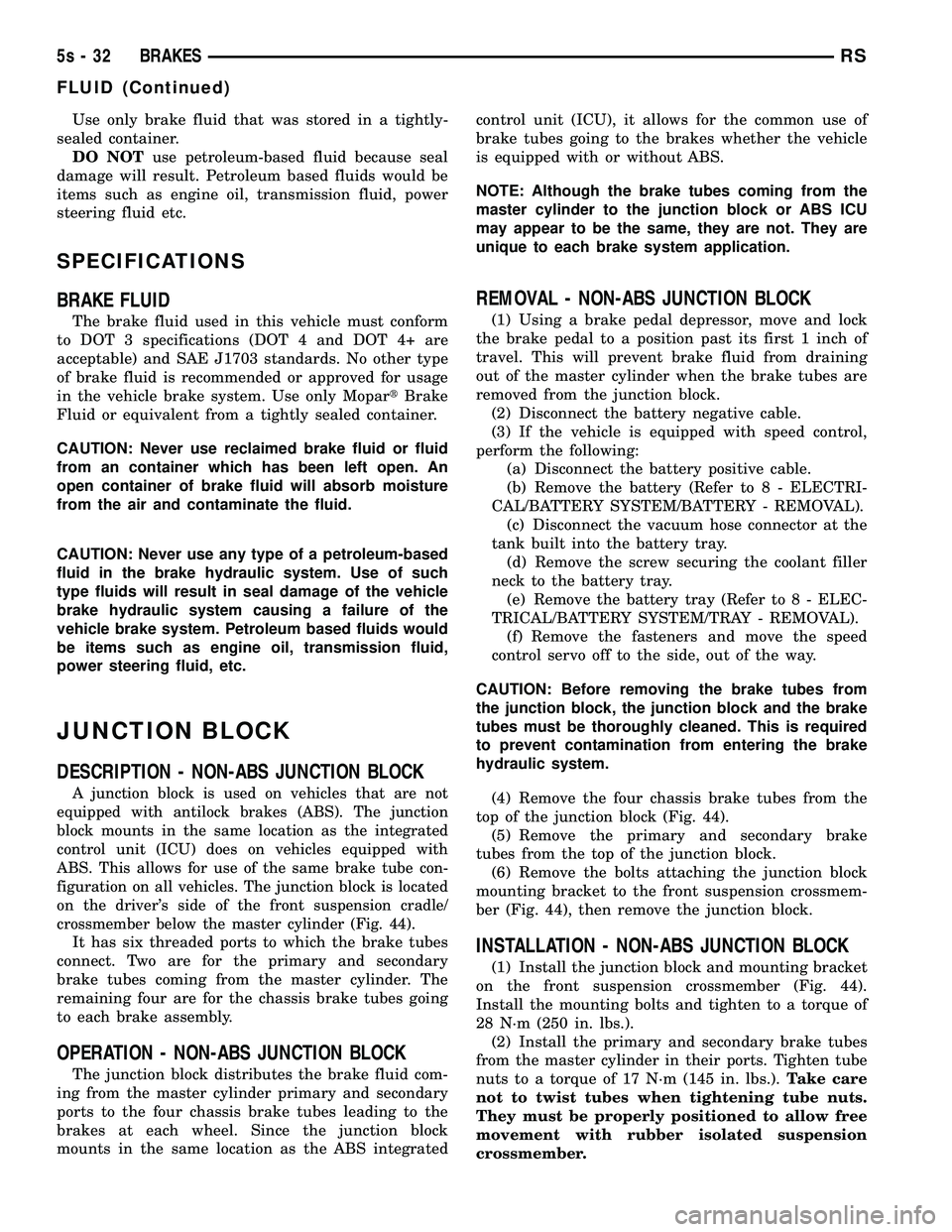
crossmember below the master cylinder (Fig. 44).
It has six threaded ports to which the brake tubes
connect. Two are for the primary and secondary
brake tubes coming from the master cylinder. The
remaining four are for the chassis brake tubes going
to each brake assembly.
OPERATION - NON-ABS JUNCTION BLOCK
The junction block distributes the brake fluid com-
ing from the master cylinder primary and secondary
ports to the four chassis brake tubes leading to the
brakes at each wheel. Since the junction block
mounts in the same location as the ABS integrated control unit (ICU), it allows for the common use of
brake tubes going to the brakes whether the vehicle
is equipped with or without ABS.
NOTE: Although the brake tubes coming from the
master cylinder to the junction block or ABS ICU
may appear to be the same, they are not. They are
unique to each brake system application.
REMOVAL - NON-ABS JUNCTION BLOCK
(1) Using a brake pedal depressor, move and lock
the brake pedal to a position past its first 1 inch of
travel. This will prevent brake fluid from draining
out of the master cylinder when the brake tubes are
removed from the junction block. (2) Disconnect the battery negative cable.
(3) If the vehicle is equipped with speed control,
perform the following: (a) Disconnect the battery positive cable.
(b) Remove the battery (Refer t o 8 - ELECTRI-
CAL/BATTERY SYSTEM/BATTERY - REMOVAL). (c) Disconnect the vacuum hose connector at the
tank built into the battery tray. (d) Remove the screw securing the coolant filler
neck to the battery tray. (e) Remove the battery tray (Refer t o 8 - ELEC-
TRICAL/BATTERY SYSTEM/TRAY - REMOVAL). (f) Remove the fasteners and move the speed
control servo off to the side, out of the way.
CAUTION: Before removing the brake tubes from
the junction block, the junction block and the brake
tubes must be thoroughly cleaned. This is required
to prevent contamination from entering the brake
hydraulic system. (4) Remove the four chassis brake tubes from the
top of the junction block (Fig. 44). (5) Remove the primary and secondary brake
tubes from the top of the junction block. (6) Remove the bolts attaching the junction block
mounting bracket to the front suspension crossmem-
ber (Fig. 44), then remove the junction block.
INSTALLATION - NON-ABS JUNCTION BLOCK
(1) Install the junction block and mounting bracket
on the front suspension crossmember (Fig. 44).
Install the mounting bolts and tighten to a torque of
28 N´m (250 in. lbs.). (2) Install the primary and secondary brake tubes
from the master cylinder in their ports. Tighten tube
nuts to a torque of 17 N´m (145 in. lbs.). Take care
not to twist tubes when tightening tube nuts.
They must be properly positioned to allow free
movement with rubber isolated suspension
crossmember.
5s - 32 BRAKESRS
FLUID (Continued)
Page 284 of 2585
(3) Install two upper mounting bolts attaching
pedals assembly to steering column support bracket
on dash panel. Do not fully tighten at this time.
(4) Install four nuts attaching pedals assembly and
power brake booster to dash panel (Fig. 61). (5) Tighten four booster mounting nuts and two
upper mounting bolts to 28 N´m (21 ft. lbs.) torque. (6) Route pedal adjuster cable up and over right
side of pedals assembly and steering column bracket, then down through hole in steering column bracket
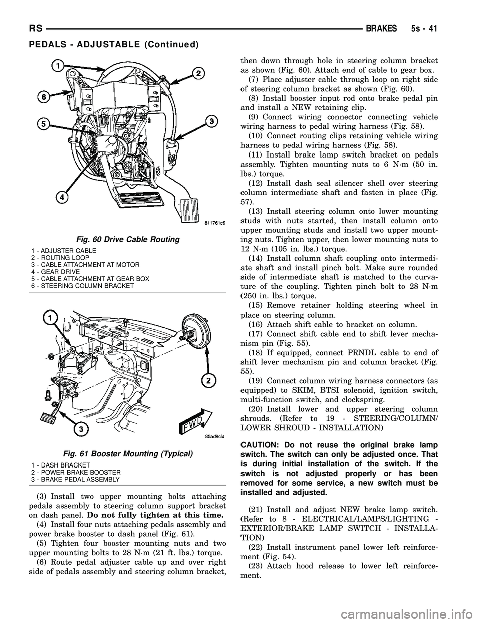
as shown (Fig. 60). Attach end of cable to gear box.
(7) Place adjuster cable through loop on right side
of steering column bracket as shown (Fig. 60). (8) Install booster input rod onto brake pedal pin
and install a NEW retaining clip. (9) Connect wiring connector connecting vehicle
wiring harness to pedal wiring harness (Fig. 58). (10) Connect routing clips retaining vehicle wiring
harness to pedal wiring harness (Fig. 58). (11) Install brake lamp switch bracket on pedals
assembly. Tighten mounting nuts to 6 N´m (50 in.
lbs.) torque. (12) Install dash seal silencer shell over steering
column intermediate shaft and fasten in place (Fig.
57). (13) Install steering column onto lower mounting
studs with nuts started, then install column onto
upper mounting studs and install two upper mount-
ing nuts. Tighten upper, then lower mounting nuts to
12 N´m (105 in. lbs.) torque. (14) Install column shaft coupling onto intermedi-
ate shaft and install pinch bolt. Make sure rounded
side of intermediate shaft is matched to the curva-
ture of the coupling. Tighten pinch bolt to 28 N´m
(250 in. lbs.) torque. (15) Remove retainer holding steering wheel in
place on steering column. (16) Attach shift cable to bracket on column.
(17) Connect shift cable end to shift lever mecha-
nism pin (Fig. 55). (18) If equipped, connect PRNDL cable to end of
shift lever mechanism pin and column bracket (Fig.
55). (19) Connect column wiring harness connectors (as
equipped) to SKIM, BTSI solenoid, ignition switch,
multi-function switch, and clockspring. (20) Install lower and upper steering column
shrouds. (Refer to 19 - STEERING/COLUMN/
LOWER SHROUD - INSTALLATION)
CAUTION: Do not reuse the original brake lamp
switch. The switch can only be adjusted once. That
is during initial installation of the switch. If the
switch is not adjusted properly or has been
removed for some service, a new switch must be
installed and adjusted.
(21) Install and adjust NEW brake lamp switch.
(Refer t o 8 - ELECTRICAL/LAMPS/LIGHTING -
EXTERIOR/BRAKE LAMP SWITCH - INSTALLA-
TION) (22) Install instrument panel lower left reinforce-
ment (Fig. 54). (23) Attach hood release to lower left reinforce-
ment.
Fig. 60 Drive Cable Routing
1 - ADJUSTER CABLE
2 - ROUTING LOOP
3 - CABLE ATTACHMENT AT MOTOR
4 - GEAR DRIVE
5 - CABLE ATTACHMENT AT GEAR BOX
6 - STEERING COLUMN BRACKET
Fig. 61 Booster Mounting (Typical)
1 - DASH BRACKET
2 - POWER BRAKE BOOSTER
3 - BRAKE PEDAL ASSEMBLY
RS BRAKES5s-41
PEDALS - ADJUSTABLE (Continued)
Page 296 of 2585

CAUTION: Do not attempt to adjust the height sens-
ing proportioning valve. If found to be defective,
replace the valve.(9) Remove the pressure test fittings and pressure
gauges from the proportioning valve. (10) Install the chassis brake lines in the correct
ports of the proportioning valve. Tighten all tube
nuts to 17 N´m (145 in. lbs.). (11) If necessary, repeat the above steps on the
remaining side of the proportioning valve which con-
trol the other rear wheel brake. (12) Attach the actuator lever and bracket to the
rear axle. (13) Bleed rear brakes. (Refer t o 5 - BRAKES -
STANDARD PROCEDURE) (14) Road test vehicle.
PROPORTIONING VALVE SPECIFICATIONS
WHEELBASE DRIVE
TRAIN SALES
CODE BRAKE
SYSTEM SPLIT
POINT SLOPE INLET
PRESSURE PSI OUTLET
PRESSURE PSI
SWB FWD BRB-BGF 15
9DISC/
DRUM W/O ANTILOCK VAR. 0.59 1000 PSI 675-875 PSI
REMOVAL - PROPORTIONING VALVE (HEIGHT
SENSING)
(1) Using a brake pedal depressor, move and lock
the brake pedal to a position past its first 1 inch of
travel. This will prevent brake fluid from draining
out of the master cylinder when the brake tubes are
removed from the proportioning valve. (2) Raise vehicle. (Refer to LUBRICATION &
MAINTENANCE/HOISTING - STANDARD PROCE-
DURE).
CAUTION: Before removing the brake tubes from
the proportioning valve, the proportioning valve and
the brake tubes must be thoroughly cleaned. This is
required to prevent contamination from entering the
proportioning valve or the brake tubes.
(3) Remove the four brake tubes from the inlet and
outlet ports of the proportioning valve (Fig. 81). (4) Remove the two bolts attaching the proportion-
ing valve and bracket to the vehicle (Fig. 81). (5) Slide the bracket out from under rear track bar
bracket. Lower the valve down enough to pull its
actuator rod out of the axle bracket and remove the
proportioning valve from the vehicle.
INSTALLATION - PROPORTIONING VALVE
(HEIGHT SENSING)
(1) Install the end of the actuator rod through the
axle bracket grommet and slide the proportioning
valve bracket under the rear track bar body bracket
(Fig. 81). (2) Install the proportioning valve attaching bolts
(Fig. 81). Tighten the attaching bolts to a torque of
54 N´m (40 ft. lbs.). (3) Install the four chassis brake lines into the
inlet and outlet ports of the proportioning valve (Fig.
81). Tighten all tube nuts to a torque of 17 N´m (145
in. lbs.).
CAUTION: The height sensing proportioning valve
is not adjustable. No attempt should be made to
adjust it.
(4) Bleed the brake system thoroughly to ensure
that all air has been expelled from the hydraulic sys-
tem. (Refer t o 5 - BRAKES - BASE - STANDARD
PROCEDURE). (5) Lower the vehicle to the ground.
Fig. 81 PROPORTIONING VALVE MOUNTING
1 - LEFT REAR OUTLET TUBE
2 - RIGHT REAR OUTLET TUBE
3 - RIGHT REAR INLET TUBE
4 - MOUNTING BOLTS
5 - LEFT REAR INLET TUBE
RS BRAKES5s-53
PROPORTIONING VALVE (Continued)