Differential & Driveline CHRYSLER VOYAGER 2004 Service Manual
[x] Cancel search | Manufacturer: CHRYSLER, Model Year: 2004, Model line: VOYAGER, Model: CHRYSLER VOYAGER 2004Pages: 2585, PDF Size: 62.54 MB
Page 1 of 2585
GROUP TAB LOCATOR
Introduction
0Lubrication & Maintenance
2Suspension
3Differential & Driveline
5Brakes
5sBrakes
6Clutch
7Cooling
8AAudio
8BChime/Buzzer
8EElectronic Control Modules
8EsElectronic Control Modules
8FEngine Systems
8FsEngine Systems
8GHeated Systems
8HHorn
8IIgnition Control
8JInstrument Cluster
8LLamps
8MMessage Systems
8NPower Systems
8NsPower Systems
8ORestraints
8PSpeed Control
8QVehicle Theft Security
8RWipers/Washers
8WWiring
9Engine
9sEngine
11Exhaust System
13Frame & Bumpers
14Fuel System
19Steering
21Transmission/Transaxle
21sTransmission/Transaxle
22Tires/Wheels
22sTires/Wheels
23Body
24Heating & Air Conditioning
25Emissions Control
Component and System Index
Service Manual Comment Forms (Rear of Manual)
Page 19 of 2585
NOTE: Intentional tampering with emissions control
systems can result in civil penalties being assessed
against you.
DESCRIPTION - FUEL REQUIREMENTS -
DIESEL ENGINE
WARNING: DO NOT USE ALCOHOL OR GASOLINE
AS A FUEL BLENDING AGENT. THEY CAN BE
UNSTABLE UNDER CERTAIN CONDITIONS AND
HAZARDOUS OR EXPLOSIVE WHEN MIXED WITH
DIESEL FUEL.
Use good quality diesel fuel from a reputable sup-
plier. For most year-round service, number 2 diesel
fuel meeting DIN EN 590 (Class0-4)will provide
good performance. If the vehicle is exposed to
extreme cold (below -18ÉC/0ÉF) or is required to oper-
ate at colder than normal conditions for prolonged
periods, use climatize No. 2 diesel fuel or dilute the
No. 2 diesel fuel with 50% No. 1 diesel fuel as long as
it meets ASTM D 975: 1D and 2D and the quality of
lubrication behavior is in accordance with DIN EN
590. This will provide better protection from fuel gel-
ling or wax plugging of the fuel filters.
Diesel fuel is seldom completely free of water. To
prevent fuel system trouble, including fuel line freez-
ing in winter, drain the accumulated water from the
fuel/water separator using the fuel/water separator
drain provided. If you buy good quality fuel and fol-
low the cold weather advice above, fuel conditioners
should not be required in your vehicle. If available in
your area, a high cetane ªpremiumº diesel fuel may
offer improved cold starting and warm up perfor-
mance.
DESCRIPTION - ENGINE OIL - DIESEL
ENGINES
Use only Diesel Engine Oil meeting standardMIL-
2104Cor API ClassificationCD or higherorCCML
D4, D5.
SAE VISCOSITY GRADE
CAUTION: Low viscosity oils must have the proper
API quality or the CCMC G5 designation.
To assure of properly formulated engine oils, it is
recommended that SAE Grade 10W-40 engine oils
that meet Chrysler material standard MS-6395, be
used in accordance to ACEA B3, B4 specification.
European Grade 10W-40 oils are also acceptable.
Oils of the SAE 5W-40 grade number are preferred
when minimum temperatures consistently fall below
-15ÉC.
DESCRIPTION - AWD REAR DRIVELINE
MODULE FLUIDS
The AWD Rear Driveline Module Assembly consists
of two subassemblies, the Overrunning Clutch Hous-
ing (front) and the Differential Carrier (rear).
The recommended lubricant for the Overrunning
Clutch Housing is MopartATF+4. The recommended
lubricant for the Differential Carrier is Mopart
80W-90 Gear and Axle Lubricant.
DESCRIPTION - AWD POWER TRANSFER UNIT
FLUID
The recommended lubricant for the AWD Power
Transfer Unit is MopartGear and Axle Lubricant
80W-90.
FLUID CAPACITIES
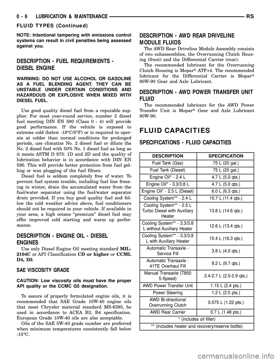
SPECIFICATIONS - FLUID CAPACITIES
DESCRIPTION SPECIFICATION
Fuel Tank (Gas) 75 L (20 gal.)
Fuel Tank (Diesel) 75 L (20 gal.)
Engine Oil* - 2.4 L 4.7 L (5.0 qts.)
Engine Oil* - 3.3/3.8 L 4.7 L (5.0 qts.)
Engine Oil* - 2.5 L (Diesel) 6.0 L (6.3 qts.)
Cooling System** - 2.4 L 10.7 L (11.4 qts.)
Cooling System** - 2.5 L
Turbo Diesel with Auxiliary
Heater13.8 L (14.6 qts.)
Cooling System** - 3.3/3.8
L without Auxiliary Heater12.6 L (13.4 qts.)
Cooling System** - 3.3/3.8
L with Auxiliary Heater15.4 L (16.3 qts.)
Automatic Transaxle -
Service Fill3.8 L (4.0 qts.)
Automatic Transaxle -
41TE Overhaul Fill9.2 L (9.7 qts.)
Manual Transaxle (T850
5-Speed)2.4-2.7 L (2.5-2.9 qts.)
AWD Power Transfer Unit 1.15 L (2.4 pts.)
Power Steering 1.2 L (2.5 pts.)
AWD Bi-directional
Overrunning Clutch0.575 L (1.22 pts.)
AWD Rear Carrier 0.7 L (1.48 pts.)
* (includes oil filter)
** (includes heater and recovery/reserve bottle)
0 - 6 LUBRICATION & MAINTENANCERS
FLUID TYPES (Continued)
Page 100 of 2585

DIFFERENTIAL & DRIVELINE
TABLE OF CONTENTS
page page
HALF SHAFT - FRONT.....................1
HALF SHAFT - REAR.....................13PROPELLER SHAFT.....................21
REAR DRIVELINE MODULE................23
HALF SHAFT - FRONT
TABLE OF CONTENTS
page page
HALF SHAFT - FRONT
DESCRIPTION..........................1
DIAGNOSIS AND TESTING - HALF SHAFT.....1
REMOVAL.............................2
INSTALLATION..........................4
SPECIFICATIONS - HALF SHAFT - FRONT....6CV BOOT - INNER
REMOVAL.............................6
INSTALLATION..........................6
CV BOOT - OUTER
REMOVAL.............................10
INSTALLATION.........................10
HALF SHAFT - FRONT
DESCRIPTION
All vehicles use an unequal length half shaft sys-
tem (Fig. 1).
The left half shaft uses a tuned rubber damper
weight. When replacing the left half shaft, be sure
the replacement half shaft has the same damper
weight as the original.
All half shaft assemblies use the same type of
inner and outer joints. The inner joint of both half
shaft assemblies is a tripod joint, and the outer joint
of both half shaft assemblies is a Rzeppa joint. Both
tripod joints and Rzeppa joints are true constant
velocity (CV) joint assemblies. The inner tripod joint
allows for the changes in half shaft length through
the jounce and rebound travel of the front suspen-
sion.
On vehicles equipped with ABS brakes, the outer
CV joint is equipped with a tone wheel used to deter-
mine vehicle speed for ABS brake operation.
The inner tripod joint of both half shafts is splined
into the transaxle side gears. The inner tripod joints
are retained in the side gears of the transaxle using
a snap ring located in the stub shaft of the tripod
joint. The outer CV joint has a stub shaft that is
splined into the wheel hub and retained by a steel
hub nut.
DIAGNOSIS AND TESTING - HALF SHAFT
VEHICLE INSPECTION
(1) Check for grease in the vicinity of the inboard
tripod joint and outboard CV joint; this is a sign of
inner or outer joint seal boot or seal boot clamp dam-
age.
NOISE AND/OR VIBRATION IN TURNS
A clicking noise and/or a vibration in turns could
be caused by one of the following conditions:
²Damaged outer CV or inner tripod joint seal
boot or seal boot clamps. This will result in the loss
and/or contamination of the joint grease, resulting in
inadequate lubrication of the joint.
²Noise may also be caused by another component
of the vehicle coming in contact with the half shafts.
CLUNKING NOISE DURING ACCELERATION
This noise may be a result of one of the following
conditions:
²A torn seal boot on the inner or outer joint of the
half shaft assembly.
²A loose or missing clamp on the inner or outer
joint of the half shaft assembly.
²A damaged or worn half shaft CV joint.
RSDIFFERENTIAL & DRIVELINE3-1
Page 105 of 2585

SPECIFICATIONS - HALF SHAFT - FRONT
TORQUE SPECIFICATIONS
DESCRIPTION N´m Ft. Lbs. In. Lbs.
Bolts, Caliper Adapter to
Knuckle169 125 -
Nut, Hub 244 180 -
Nuts, Front Wheel Lug 135 100 -
Nut, Tie Rod End to
Knuckle75 55 -
Nut, Strut Clevis to
Knuckle81 +90É 60 +90É -
CV BOOT - INNER
REMOVAL
(1) Remove the half shaft requiring boot replace-
ment from the vehicle. (Refer to 3 - DIFFERENTIAL
& DRIVELINE/HALF SHAFT - REMOVAL)
(2) Remove large boot clamp which retains inner
tripod joint sealing boot to tripod joint housing and
discard.
(3) Remove small clamp which retains inner tripod
joint sealing boot to interconnecting shaft and dis-
card.
(4) Remove the sealing boot from the tripod hous-
ing and slide it down the interconnecting shaft.
(5) Slide the tripod joint housing off the spider
assembly and the interconnecting shaft (Fig. 12).
(6) Remove snap-ring which retains spider assem-
bly to interconnecting shaft (Fig. 13).Do not hit theouter tripod bearings in an attempt to remove
spider assembly from interconnecting shaft.
(7) Remove the spider assembly from interconnect-
ing shaft. If spider assembly will not come off inter-
connecting shaft by hand, it can be removed by
tapping spider assembly with a brass drift (Fig. 14).
(8) Slide sealing boot off interconnecting shaft.
(9) Thoroughly clean and inspect spider assembly,
tripod joint housing, and interconnecting shaft for
any signs of excessive wear.If any parts show
signs of excessive wear, the half shaft assembly
will require replacement. Component parts of
these half shaft assemblies are not serviceable.
INSTALLATION
(1) Slide inner CV joint seal boot retaining clamp,
onto the interconnecting shaft. Then, slide the
replacement inner CV joint sealing boot onto the
interconnecting shaft.Inner CV joint seal boot
Fig. 12 Spider Assembly Removal from Tripod Joint
Housing
1 - TRIPOD JOINT HOUSING
2 - SPIDER ASSEMBLY
3 - SEALING BOOT
Fig. 13 Spider Assembly Retaining Snap-Ring
1 - INTERCONNECTING SHAFT
2 - SPIDER ASSEMBLY
3 - RETAINING SNAP-RING
3 - 6 HALF SHAFT - FRONTRS
HALF SHAFT - FRONT (Continued)
Page 109 of 2585

LATCHING TYPE BOOT CLAMP
If seal boot uses low profile latching type boot
clamp, use the following procedure to install the
retaining clamp.
(1) Place prongs of clamp locking tool in the holes
of the clamp (Fig. 25).
(2) Squeeze tool together until top band of clamp is
latched behind the two tabs on lower band of clamp
(Fig. 26).
(14) Install the half shaft back into the vehicle.
(Refer to 3 - DIFFERENTIAL & DRIVELINE/HALF
SHAFT - INSTALLATION)
CV BOOT - OUTER
REMOVAL
(1) Remove half shaft assembly requiring boot
replacement from vehicle. (Refer to 3 - DIFFEREN-
TIAL & DRIVELINE/HALF SHAFT - REMOVAL)
(2) Remove large boot clamp retaining CV joint
sealing boot to CV joint housing (Fig. 27) and dis-
card.
(3) Remove small clamp that retains outer CV
joint sealing boot to interconnecting shaft and dis-
card.
(4) Remove sealing boot from outer CV joint hous-
ing and slide it down interconnecting shaft.
(5) Wipe away grease to expose outer CV joint to
interconnecting shaft retaining ring.
(6) Spread ears apart on CV joint assembly to
interconnecting shaft retaining ring (Fig. 28).
(7) Slide outer CV joint assembly off end of inter-
connecting shaft.
(8) Slide sealing boot off interconnecting shaft.
(9) Thoroughly clean and inspect outer CV joint
assembly and interconnecting joint for any signs of
excessive wear.If any parts show signs of exces-
sive wear, the half shaft assembly will require
replacement. Component parts of these half
shaft assemblies are not serviceable.
INSTALLATION
(1) Slide the new small diameter seal boot retain-
ing clamp onto the interconnecting shaft. Then slide
the replacement outer CV joint assembly sealing boot
onto the interconnecting shaft.
Fig. 25 Clamping Tool Installed on Sealing Boot
Clamp
1 - CLAMP
2 - TOOL YA3050, OR EQUIVALENT
3 - SEALING BOOT
Fig. 26 Sealing Boot Clamp Correctly Installed
1 - INNER TRIPOD JOINT HOUSING
2 - TOP BAND OF CLAMP MUST BE RETAINED BY TABS AS
SHOWN HERE TO CORRECTLY LATCH BOOT CLAMP
3 - SEALING BOOT
Fig. 27 Outer CV Joint Seal Boot Clamps
1 - SMALL CLAMP
2 - SEALING BOOT
3 - OUTER C/V JOINT HOUSING
4 - LARGE CLAMP
5 - INTERCONNECTING SHAFT
3 - 10 HALF SHAFT - FRONTRS
CV BOOT - INNER (Continued)
Page 114 of 2585

(5) Install the spring washer, nut lock, and a new
cotter pin (Fig. 6). Be sure to wrap the cotter pin
prongs tightly around the hub nut lock.
(6) Install rear wheel. Torque the lug nuts to 135
N´m (100 ft.lbs.).
SPECIFICATIONS - HALF SHAFT - FRONT
TORQUE SPECIFICATIONS
DESCRIPTION N´m Ft. Lbs. In. Lbs.
Nut, Hub 244 180 -
Nuts, Rear Wheel Lug 135 100 -
Bolt, Half Shaft to Output
Flange61 45 -
CV BOOT - INNER/OUTER
REMOVAL
(1) Remove half shaft from vehicle. (Refer to 3 -
DIFFERENTIAL & DRIVELINE/HALF SHAFT -
REMOVAL)
(2) Clamp the half shaft into a suitable vise with
protective jaws clamped onto the interconnecting
shaft (Fig. 7).
Fig. 6 Cotter Pin, Nut Lock, And Spring Washer
1 - HUB NUT
2 - NUT LOCK
3 - COTTER PIN
4 - SPRING WASHER
Fig. 7 Clamp Shaft In Soft Jawed Vice
1 - HALF SHAFT BOOT
2 - HALF SHAFT
3 - VISE
RSHALF SHAFT - REAR3-15
HALF SHAFT - REAR (Continued)
Page 119 of 2585

LATCHING TYPE BOOT CLAMP
If seal boot uses low profile latching type boot
clamp, use the following procedure to install the
retaining clamp.
(1) Place prongs of clamp locking tool in the holes
of the clamp (Fig. 23).
(2) Squeeze tool together until top band of clamp is
latched behind the two tabs on lower band of clamp
(Fig. 24).
(16) Install the half shaft into the vehicle. (Refer
to 3 - DIFFERENTIAL & DRIVELINE/HALF SHAFT
- INSTALLATION)
Fig. 23 Clamping Tool Installed on Sealing Boot
Clamp
1 - CLAMP
2 - TOOL YA3050, OR EQUIVALENT
3 - SEALING BOOT
Fig. 24 Sealing Boot Clamp Correctly Installed
1 - INNER TRIPOD JOINT HOUSING
2 - TOP BAND OF CLAMP MUST BE RETAINED BY TABS AS
SHOWN HERE TO CORRECTLY LATCH BOOT CLAMP
3 - SEALING BOOT
3 - 20 HALF SHAFT - REARRS
CV BOOT - INNER/OUTER (Continued)
Page 122 of 2585
REAR DRIVELINE MODULE
TABLE OF CONTENTS
page page
REAR DRIVELINE MODULE
DESCRIPTION.........................23
OPERATION...........................23
DIAGNOSIS AND TESTING
DIAGNOSIS AND TESTING - REAR
DRIVELINE MODULE NOISE.............24
DIAGNOSIS AND TESTING - REAR
DRIVELINE MODULE OPERATION........26
REMOVAL.............................26
DISASSEMBLY.........................27
ASSEMBLY............................29
INSTALLATION.........................33
SPECIFICATIONS - REAR DRIVELINE
MODULE............................34
SPECIAL TOOLS.......................34
BI-DIRECTIONAL OVERRUNNING CLUTCH
DESCRIPTION.........................34
OPERATION...........................36
DIFFERENTIAL ASSEMBLY
DESCRIPTION.........................39OPERATION...........................39
FLUID - DIFFERENTIAL ASSEMBLY
STANDARD PROCEDURE - DIFFERENTIAL
ASSEMBLY FLUID CHANGE.............40
FLUID - OVERRUNNING CLUTCH HOUSING
STANDARD PROCEDURE - OVERRUNNING
CLUTCH HOUSING FLUID CHANGE.......41
VISCOUS COUPLER
DESCRIPTION.........................41
OPERATION...........................42
TORQUE ARM
REMOVAL.............................44
INSTALLATION.........................44
INPUT FLANGE SEAL
REMOVAL.............................44
INSTALLATION.........................45
OUTPUT FLANGE SEAL
REMOVAL.............................45
INSTALLATION.........................46
REAR DRIVELINE MODULE
DESCRIPTION
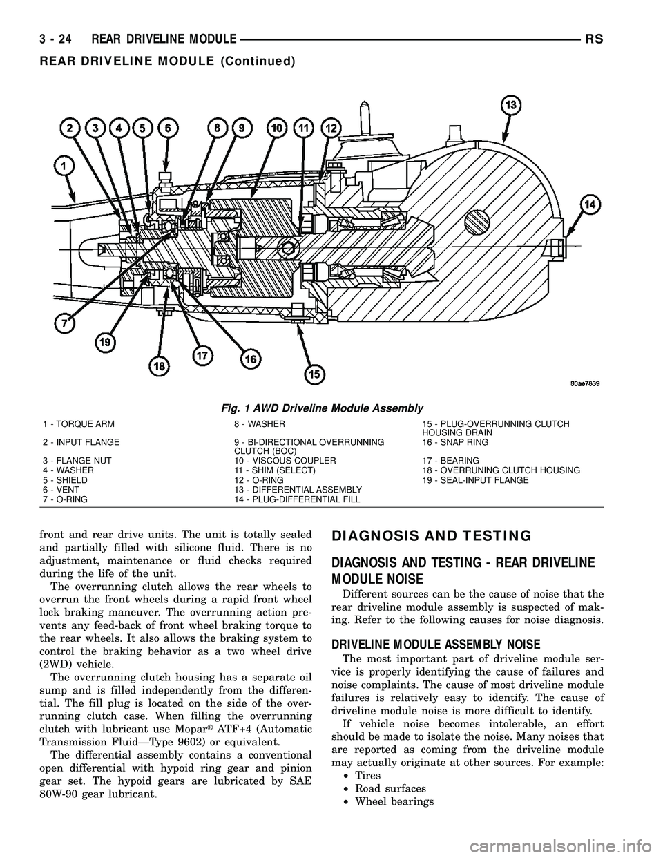
The rear driveline module assembly (Fig. 1) con-
sists of four main components:
²Bi-Directional Overrunning Clutch (BOC)
²Viscous Coupling
²Differential Assembly
²Torque Arm
The viscous coupling and bi-directional overrun-
ning clutch are contained within an overrunning
clutch housing, which fastens to the differential
assembly. The overrunning clutch housing and differ-
ential assembly have unique fluid sumps, each
requiring their own type and capacity of fluid. The
overrunning clutch housing requires MopartATF+4
(Automatic Transmission FluidÐType 9602) or equiv-
alent. The differential assembly requires Mopart
80W-90 Gear and Axle Lubricant.
Driveline module service is limited to the following
components:
²Differential Assembly (serviced only as assem-
bly)
²Viscous Coupling
²Bi-Directional Overrunning Clutch (BOC)
²Overrunning Clutch Housing²Seals (Input Flange, Output Flange, Overrun-
ning Clutch Housing O-rings)
²Input Flange/Shield
²Torque Arm
²Vents
²Fasteners
OPERATION
The primary benefits of All Wheel Drive are:
²Superior straight line acceleration, and corner-
ing on all surfaces
²Better traction and handling under adverse con-
ditions, resulting in improved hill climbing ability
and safer driving.
The heart of the system is an inter-axle viscous
coupling. The vehicle retains predominantly front-
wheel drive characteristics, but the All Wheel Drive
capability takes effect when the front wheels start to
slip. Under normal level road, straight line driving,
100% of the torque is allocated to the front wheels.
The viscous coupling controls and distributes torque/
power to the rear wheels. The viscous coupling trans-
mits torque to the rear wheels in proportion of the
amount of the slippage at the front wheels. Thais
variable torque distribution is automatic with no
driver inputs required. The coupling is similar to a
multi-plate clutch. It consists of a series of closely
spaced discs, which are alternately connected to the
RSREAR DRIVELINE MODULE3-23
Page 123 of 2585
front and rear drive units. The unit is totally sealed
and partially filled with silicone fluid. There is no
adjustment, maintenance or fluid checks required
during the life of the unit.
The overrunning clutch allows the rear wheels to
overrun the front wheels during a rapid front wheel
lock braking maneuver. The overrunning action pre-
vents any feed-back of front wheel braking torque to
the rear wheels. It also allows the braking system to
control the braking behavior as a two wheel drive
(2WD) vehicle.
The overrunning clutch housing has a separate oil
sump and is filled independently from the differen-
tial. The fill plug is located on the side of the over-
running clutch case. When filling the overrunning
clutch with lubricant use MopartATF+4 (Automatic
Transmission FluidÐType 9602) or equivalent.
The differential assembly contains a conventional
open differential with hypoid ring gear and pinion
gear set. The hypoid gears are lubricated by SAE
80W-90 gear lubricant.DIAGNOSIS AND TESTING
DIAGNOSIS AND TESTING - REAR DRIVELINE
MODULE NOISE
Different sources can be the cause of noise that the
rear driveline module assembly is suspected of mak-
ing. Refer to the following causes for noise diagnosis.
DRIVELINE MODULE ASSEMBLY NOISE
The most important part of driveline module ser-
vice is properly identifying the cause of failures and
noise complaints. The cause of most driveline module
failures is relatively easy to identify. The cause of
driveline module noise is more difficult to identify.
If vehicle noise becomes intolerable, an effort
should be made to isolate the noise. Many noises that
are reported as coming from the driveline module
may actually originate at other sources. For example:
²Tires
²Road surfaces
²Wheel bearings
Fig. 1 AWD Driveline Module Assembly
1 - TORQUE ARM 8 - WASHER 15 - PLUG-OVERRUNNING CLUTCH
HOUSING DRAIN
2 - INPUT FLANGE 9 - BI-DIRECTIONAL OVERRUNNING
CLUTCH (BOC)16 - SNAP RING
3 - FLANGE NUT 10 - VISCOUS COUPLER 17 - BEARING
4 - WASHER 11 - SHIM (SELECT) 18 - OVERRUNING CLUTCH HOUSING
5 - SHIELD 12 - O-RING 19 - SEAL-INPUT FLANGE
6 - VENT 13 - DIFFERENTIAL ASSEMBLY
7 - O-RING 14 - PLUG-DIFFERENTIAL FILL
3 - 24 REAR DRIVELINE MODULERS
REAR DRIVELINE MODULE (Continued)
Page 124 of 2585

²Engine
²Transmission
²Exhaust
²Propeller shaft (vibration)
²Vehicle body (drumming)
Driveline module noises are normally divided into
two categories: gear noise or bearing noise. A thor-
ough and careful inspection should be completed to
determine the actual source of the noise before
replacing the driveline module.
The rubber mounting bushings help to dampen-out
driveline module noise when properly installed.
Inspect to confirm that no metal contact exists
between the driveline module case and the body. The
complete isolation of noise to one area requires
expertise and experience. Identifying certain types of
vehicle noise baffles even the most capable techni-
cians. Often such practices as:
²Increase tire inflation pressure to eliminate tire
noise.
²Listen for noise at varying speeds with different
driveline load conditions
²Swerving the vehicle from left to right to detect
wheel bearing noise.
All driveline module assemblies produce noise to a
certain extent. Slight carrier noise that is noticeable
only at certain speeds or isolated situations should be
considered normal. Carrier noise tends to peak at a
variety of vehicle speeds. Noise isNOT ALWAYSan
indication of a problem within the carrier.
TIRE NOISE
Tire noise is often mistaken for driveline module
noise. Tires that are unbalanced, worn unevenly or
are worn in a saw-tooth manner are usually noisy.
They often produce a noise that appears to originate
in the driveline module.
Tire noise changes with different road surfaces, but
driveline module noise does not. Inflate all four tires
with approximately 20 psi (138 kPa) more than the
recommended inflation pressure (for test purposes
only). This will alter noise caused by tires, but will
not affect noise caused by the differential. Rear axle
noise usually ceases when coasting at speeds less
than 30 mph (48 km/h); however, tire noise contin-
ues, but at a lower frequency, as the speed is
reduced.
After test has been completed lower tire pressure
back to recommended pressure.
GEAR NOISE (DRIVE PINION AND RING GEAR)
Abnormal gear noise is rare and is usually caused
by scoring on the ring gear and drive pinion. Scoring
is the result of insufficient or incorrect lubricant in
the carrier housing.Abnormal gear noise can be easily recognized. It
produces a cycling tone that will be very pronounced
within a given speed range. The noise can occur dur-
ing one or more of the following drive conditions:
²Drive
²Road load
²Float
²Coast
Abnormal gear noise usually tends to peak within
a narrow vehicle speed range or ranges. It is usually
more pronounced between 30 to 40 mph (48 to 64
km/h) and 50 to 60 mph (80 to 96 km/h). When objec-
tionable gear noise occurs, note the driving condi-
tions and the speed range.
BEARING NOISE (DRIVE PINION AND
DIFFERENTIAL)
Defective bearings produce a rough growl that is
constant in pitch and varies with the speed of vehi-
cle. Being aware of this will enable a technician to
separate bearing noise from gear noise.
Drive pinion bearing noise that results from defec-
tive or damaged bearings can usually be identified by
its constant, rough sound. Drive pinion front bearing
is usually more pronounced during a coast condition.
Drive pinion rear bearing noise is more pronounced
during a drive condition. The drive pinion bearings
are rotating at a higher rate of speed than either the
differential side bearings or the axle shaft bearing.
Differential side bearing noise will usually produce
a constant, rough sound. The sound is much lower in
frequency than the noise caused by drive pinion bear-
ings.
Bearing noise can best be detected by road testing
the vehicle on a smooth road (black top). However, it
is easy to mistake tire noise for bearing noise. If a
doubt exists, the tire treads should be examined for
irregularities that often causes a noise that resem-
bles bearing noise.
ENGINE AND TRANSMISSION NOISE
Sometimes noise that appears to be in the driv-
eline module assembly is actually caused by the
engine or the transmission. To identify the true
source of the noise, note the approximate vehicle
speed and/or RPM when the noise is most noticeable.
Stop the vehicle next to a flat brick or cement wall
(this will help reflect the sound). Place the transaxle
inNEUTRAL. Accelerate the engine slowly up
through the engine speed that matches the vehicle
speed noted when the noise occurred. If the same
noise is produced, it usually indicates that the noise
is being caused by the engine or transaxle.
RSREAR DRIVELINE MODULE3-25
REAR DRIVELINE MODULE (Continued)