Low side CHRYSLER VOYAGER 2004 Service Manual
[x] Cancel search | Manufacturer: CHRYSLER, Model Year: 2004, Model line: VOYAGER, Model: CHRYSLER VOYAGER 2004Pages: 2585, PDF Size: 62.54 MB
Page 12 of 2585

VEHICLE CERTIFICATION
LABEL
DESCRIPTION
A vehicle certification label is attached to the rear
shutface of the driver's door (Fig. 8). This label indi-
cates date of manufacture (month and year), Gross
Vehicle Weight Rating (GVWR), Gross Axle Weight
Rating (GAWR) front, Gross Axle Weight Rating
(GAWR) rear and the Vehicle Identification Number
(VIN). The Month, Day and Hour of manufacture is
also included.
All communications or inquiries regarding the
vehicle should include the Month-Day-Hour and
Vehicle Identification Number.
E-MARK LABEL
DESCRIPTION
An E-mark Label (Fig. 9) is located on the rear
shut face of the driver's door. The label contains the
following information:
²Date of Manufacture
²Month-Day-Hour (MDH)
²Vehicle Identification Number (VIN)
²Country Codes
²Regulation Number
²Regulation Amendment Number
²Approval Number
VECI LABEL
DESCRIPTION
All models have a Vehicle Emission Control Informa-
tion (VECI) Label. Chrysler permanently attaches the
label in the engine compartment. It cannot be removed
without defacing information and destroying the label.
The label contains the vehicle's emission specifica-
tions and vacuum hose routings. All hoses must be
connected and routed according to the label.
MANUFACTURER PLATE
DESCRIPTION
The Manufacturer Plate (Fig. 10) is located in the
engine compartment on the passenger side rear corner
of the hood. The plate contains five lines of information:
1. Vehicle Identification Number (VIN)
2. Gross Vehicle Mass (GVM)
3. Gross Train Mass (GTM)
4. Gross Front Axle Rating (GFAR)
5. Gross Rear Axle Rating (GRAR)
Fig. 8 VEHICLE CERTIFICATION LABEL - TYPICAL
Fig. 9 E-MARK LABEL
1 - COUNTRY CODE
2 - REGULATION NUMBER
3 - APPROVAL NUMBER
4 - AMENDMENT NUMBER
Fig. 10 MANUFACTURER PLATE
RSINTRODUCTION11
Page 18 of 2585
ence these symptoms, try another brand of gasoline
before considering service for the vehicle.
Over 40 auto manufacturers world-wide have
issued and endorsed consistent gasoline specifications
(the Worldwide Fuel Charter, WWFC) to define fuel
properties necessary to deliver enhanced emissions,
performance and durability for your vehicle. We rec-
ommend the use of gasolines that meet the WWFC
specifications if they are available.
REFORMULATED GASOLINE
Many areas of the country require the use of
cleaner burning gasoline referred to as ªreformu-
latedº gasoline. Reformulated gasoline contain oxy-
genates, and are specifically blended to reduce
vehicle emissions and improve air quality.
We strongly support the use of reformulated gaso-
line. Properly blended reformulated gasoline will pro-
vide excellent performance and durability for the
engine and fuel system components.
GASOLINE/OXYGENATE BLENDS
Some fuel suppliers blend unleaded gasoline with
oxygenates such as 10% ethanol, MTBE, and ETBE.
Oxygenates are required in some areas of the country
during the winter months to reduce carbon monoxide
emissions. Fuels blended with these oxygenates may
be used in your vehicle.
CAUTION: DO NOT use gasoline containing METH-
ANOL. Gasoline containing methanol may damage
critical fuel system components.
MMT IN GASOLINE
MMT is a manganese-containing metallic additive
that is blended into some gasoline to increase octane.
Gasoline blended with MMT provide no performance
advantage beyond gasoline of the same octane num-
ber without MMT. Gasoline blended with MMT
reduce spark plug life and reduce emission system
performance in some vehicles. We recommend that
gasoline free of MMT be used in your vehicle. The
MMT content of gasoline may not be indicated on the
gasoline pump; therefore, you should ask your gaso-
line retailer whether or not his/her gasoline contains
MMT.
It is even more important to look for gasoline with-
out MMT in Canada because MMT can be used at
levels higher than allowed in the United States.
MMT is prohibited in Federal and California refor-
mulated gasoline.
SULFUR IN GASOLINE
If you live in the northeast United States, your
vehicle may have been designed to meet California
low emission standards with Cleaner-Burning Cali-fornia reformulated gasoline with low sulfur. If such
fuels are not available in states adopting California
emission standards, your vehicles will operate satis-
factorily on fuels meeting federal specifications, but
emission control system performance may be
adversely affected. Gasoline sold outside of California
is permitted to have higher sulfur levels which may
affect the performance of the vehicle's catalytic con-
verter. This may cause the Malfunction Indicator
Lamp (MIL), Check Engine or Service Engine Soon
light to illuminate. We recommend that you try a dif-
ferent brand of unleaded gasoline having lower sulfur
to determine if the problem is fuel related prior to
returning your vehicle to an authorized dealer for
service.
CAUTION: If the Malfunction Indicator Lamp (MIL),
Check Engine or Service Engine Soon light is flash-
ing, immediate service is required; see on-board
diagnostics system section.
MATERIALS ADDED TO FUEL
All gasoline sold in the United States and Canada
are required to contain effective detergent additives.
Use of additional detergents or other additives is not
needed under normal conditions.
FUEL SYSTEM CAUTIONS
CAUTION: Follow these guidelines to maintain your
vehicle's performance:
²The use of leaded gas is prohibited by Federal
law. Using leaded gasoline can impair engine perfor-
mance, damage the emission control system, and
could result in loss of warranty coverage.
²An out-of-tune engine, or certain fuel or ignition
malfunctions, can cause the catalytic converter to
overheat. If you notice a pungent burning odor or
some light smoke, your engine may be out of tune or
malfunctioning and may require immediate service.
Contact your dealer for service assistance.
²When pulling a heavy load or driving a fully
loaded vehicle when the humidity is low and the tem-
perature is high, use a premium unleaded fuel to
help prevent spark knock. If spark knock persists,
lighten the load, or engine piston damage may result.
²The use of fuel additives which are now being
sold as octane enhancers is not recommended. Most
of these products contain high concentrations of
methanol. Fuel system damage or vehicle perfor-
mance problems resulting from the use of such fuels
or additives is not the responsibility of
DaimlerChrysler Corporation and may not be covered
under the new vehicle warranty.
RSLUBRICATION & MAINTENANCE0-5
FLUID TYPES (Continued)
Page 45 of 2585

FRONT SUSPENSION
DESCRIPTION - FRONT SUSPENSION
This vehicle has a MacPherson Strut type front
suspension (Fig. 1).
OPERATION - FRONT SUSPENSION
The front suspension allows each wheel on a vehi-
cle to adapt to different road surfaces and conditions
without greatly affecting the opposite wheel and the
ability to control the vehicle. Each side of the front
suspension is allowed to pivot so the vehicle can be
steered in the direction preferred.
A strut assembly is used in place of the front sus-
pension upper control arm and upper ball joint.
When a vehicle strikes a bump, the force is trans-
ferred through the hub, bearing, and knuckle, into
the strut assembly to absorb the force and dampen it.
The top of the strut is mounted directly to the strut
tower of the vehicle. During steering maneuvers, the
strut assembly (through a pivot bearing in the upperstrut mount) and steering knuckle (through the lower
ball joint) turn as an assembly.
STANDARD PROCEDURE - LUBRICATION
There are no serviceable lubrication points on the
front suspension. The ball joints are sealed-for-life
and require no maintenance. The lower ball joints
have special grease fitting caps that prevent normal
grease gun attachment. This has been done to elimi-
nate the possibility of over-filling, damaging the non-
vented seal. Do not attempt to remove the special
grease fitting cap and replace it with a normal grease
zirc fitting.
CAUTION: No attempt should be made to replace
the ball joint grease fitting cap with a normal zirc
fitting or fill the ball joint with grease. Damage to
the grease seal can result.
Fig. 1 Front Suspension
1 - TOWER
2 - CROSSMEMBER TAPPING PLATES
3 - LEFT STRUT ASSEMBLY
4 - LEFT STEERING KNUCKLE (WITH HUB AND BEARING)
5 - STABILIZER BAR LINK
6 - STABILIZER BAR
7 - LEFT LOWER CONTROL ARM
8 - CRADLE/CROSSMEMBER9 - CRADLE/CROSSMEMBER REINFORCEMENT
10 - BALL JOINT
11 - ISOLATOR BUSHING
12 - STEERING GEAR TIE ROD
13 - RIGHT STEERING KNUCKLE
14 - RIGHT HUB AND BEARING
15 - RIGHT STRUT ASSEMBLY
2 - 2 FRONT SUSPENSIONRS
Page 47 of 2585

BUSHINGS
REMOVAL - STABILIZER BAR CUSHION
(1) Raise Vehicle. Refer to Hoisting in Lubrication
and Maintenance.
(2) Remove the 2 bolts fastening the emission leak
detection pump to the cradle crossmember reinforce-
ment.
(3) Move the leak detection pump to the side
allowing access to the stabilizer bar cushion retain-
ers.
(4) Remove the nut and bolt securing each stabi-
lizer bar cushion retainer to the cradle crossmember
(Fig. 2) and remove the retainers.
(5) Remove each stabilizer bar cushion from the
stabilizer bar by opening the slit in the cushion and
peeling it off the stabilizer bar.
INSTALLATION - STABILIZER BAR CUSHION
(1) Install each new cushion on stabilizer bar by
spreading cushion at slit and forcing it onto stabilizer
bar.
NOTE: Cushions must be installed on stabilizer bar
so the square corner of the bushing will be down
and slit in cushion will be facing the rear of the
vehicle when the stabilizer bar is installed (Fig. 3).
(2) Place stabilizer bar into mounted position with
cushions properly aligned.
(3) Hook each retainer into cradle crossmember
mounting hole and over cushion.(4) Install each mounting bolt from rear of cradle
crossmember through retainer. Install the two nuts
and tighten to 68 N´m (50 ft. lbs.) torque.
(5) Reattach emission leak detection pump to cra-
dle crossmember reinforcement with two mounting
bolts.
(6) Lower the vehicle.
HUB / BEARING
DESCRIPTION
The front wheel bearing and front wheel hub of
this vehicle are a hub and bearing unit type assem-
bly (Unit III). This unit combines the front wheel
mounting hub (flange) and the front wheel bearing
into a sealed one-piece unit. The hub and bearing is
mounted to the center of the steering knuckle (Fig.
1). It is retained by four mounting bolts accessible
from the inboard side of the steering knuckle. The
hub flange has five wheel mounting studs.
The wheel mounting studs used to mount the tire
and wheel to the vehicle are the only replaceable
components of the hub and bearing assembly. Other-
wise, the hub and bearing is serviced only as a com-
plete assembly.
OPERATION
The hub and bearing has internal bearings that
allow the hub to rotate with the driveshaft, along
with the tire and wheel. The five wheel mounting
studs mount the tire and wheel, and brake rotor to
the vehicle.
Fig. 2 Front Stabilizer Bar Cushion Retainers
1 - STEERING GEAR
2 - STABILIZER BAR
3 - RAISED BEAD
4 - FRONT CRADLE CROSSMEMBER
5 - RETAINERS
Fig. 3 Correctly Installed Stabilizer Bar Cushion
1 - SLIT IN SWAY BAR BUSHING.
2 - SQUARE CORNER
3-SWAYBAR
4 - SWAY BAR ISOLATOR BUSHING
2 - 4 FRONT SUSPENSIONRS
Page 51 of 2585
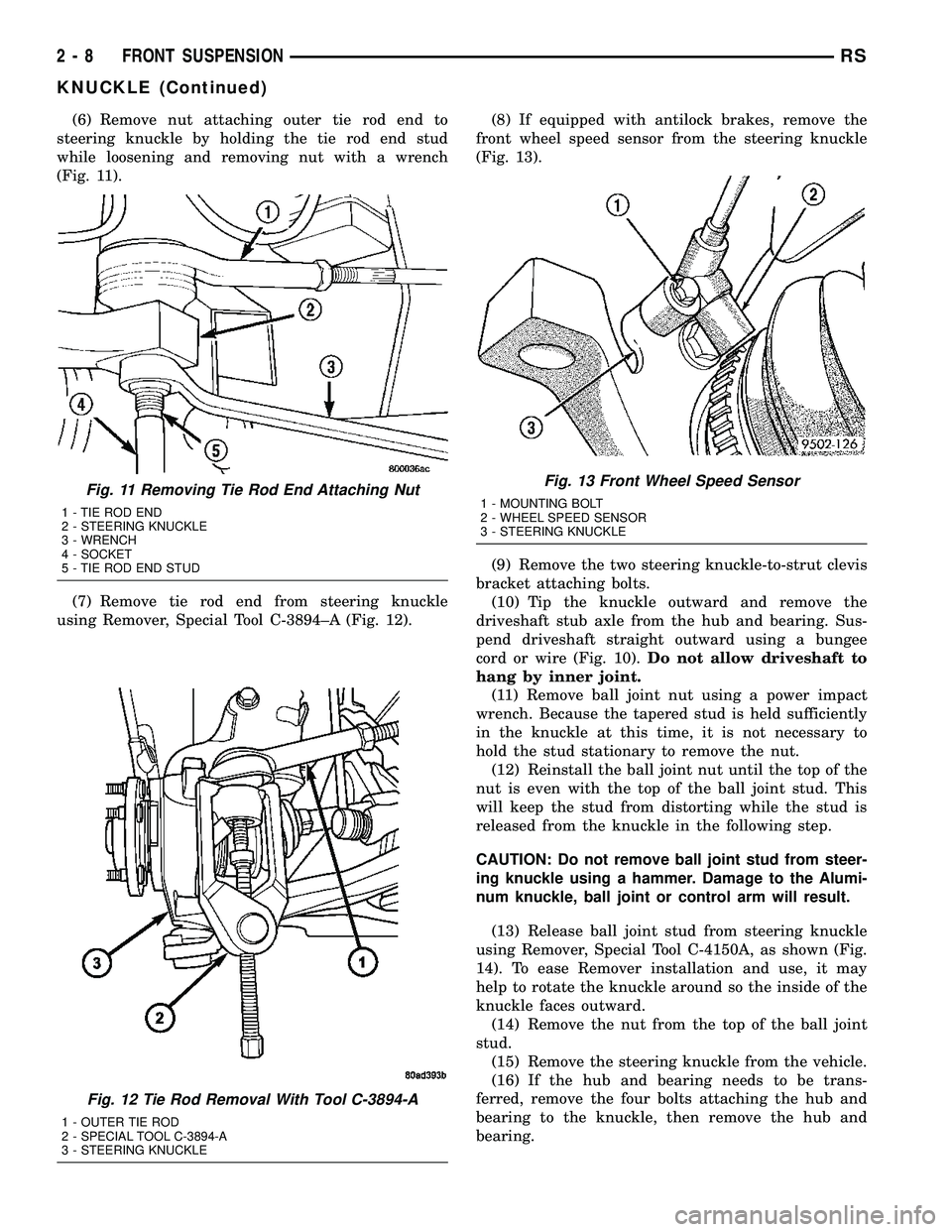
(6) Remove nut attaching outer tie rod end to
steering knuckle by holding the tie rod end stud
while loosening and removing nut with a wrench
(Fig. 11).
(7) Remove tie rod end from steering knuckle
using Remover, Special Tool C-3894±A (Fig. 12).(8) If equipped with antilock brakes, remove the
front wheel speed sensor from the steering knuckle
(Fig. 13).
(9) Remove the two steering knuckle-to-strut clevis
bracket attaching bolts.
(10) Tip the knuckle outward and remove the
driveshaft stub axle from the hub and bearing. Sus-
pend driveshaft straight outward using a bungee
cord or wire (Fig. 10).Do not allow driveshaft to
hang by inner joint.
(11) Remove ball joint nut using a power impact
wrench. Because the tapered stud is held sufficiently
in the knuckle at this time, it is not necessary to
hold the stud stationary to remove the nut.
(12) Reinstall the ball joint nut until the top of the
nut is even with the top of the ball joint stud. This
will keep the stud from distorting while the stud is
released from the knuckle in the following step.
CAUTION: Do not remove ball joint stud from steer-
ing knuckle using a hammer. Damage to the Alumi-
num knuckle, ball joint or control arm will result.
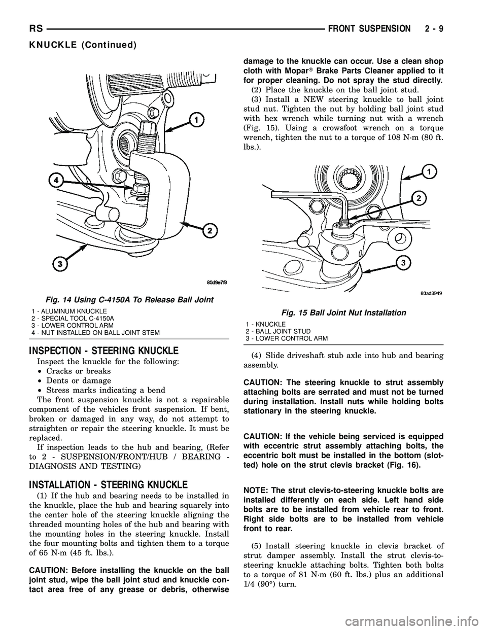
(13) Release ball joint stud from steering knuckle
using Remover, Special Tool C-4150A, as shown (Fig.
14). To ease Remover installation and use, it may
help to rotate the knuckle around so the inside of the
knuckle faces outward.
(14) Remove the nut from the top of the ball joint
stud.
(15) Remove the steering knuckle from the vehicle.
(16) If the hub and bearing needs to be trans-
ferred, remove the four bolts attaching the hub and
bearing to the knuckle, then remove the hub and
bearing.
Fig. 11 Removing Tie Rod End Attaching Nut
1 - TIE ROD END
2 - STEERING KNUCKLE
3 - WRENCH
4 - SOCKET
5 - TIE ROD END STUD
Fig. 12 Tie Rod Removal With Tool C-3894-A
1 - OUTER TIE ROD
2 - SPECIAL TOOL C-3894-A
3 - STEERING KNUCKLE
Fig. 13 Front Wheel Speed Sensor
1 - MOUNTING BOLT
2 - WHEEL SPEED SENSOR
3 - STEERING KNUCKLE
2 - 8 FRONT SUSPENSIONRS
KNUCKLE (Continued)
Page 52 of 2585
INSPECTION - STEERING KNUCKLE
Inspect the knuckle for the following:
²Cracks or breaks
²Dents or damage
²Stress marks indicating a bend
The front suspension knuckle is not a repairable
component of the vehicles front suspension. If bent,
broken or damaged in any way, do not attempt to
straighten or repair the steering knuckle. It must be
replaced.
If inspection leads to the hub and bearing, (Refer
to 2 - SUSPENSION/FRONT/HUB / BEARING -
DIAGNOSIS AND TESTING)
INSTALLATION - STEERING KNUCKLE
(1) If the hub and bearing needs to be installed in
the knuckle, place the hub and bearing squarely into
the center hole of the steering knuckle aligning the
threaded mounting holes of the hub and bearing with
the mounting holes in the steering knuckle. Install
the four mounting bolts and tighten them to a torque
of 65 N´m (45 ft. lbs.).
CAUTION: Before installing the knuckle on the ball
joint stud, wipe the ball joint stud and knuckle con-
tact area free of any grease or debris, otherwisedamage to the knuckle can occur. Use a clean shop
cloth with MoparTBrake Parts Cleaner applied to it
for proper cleaning. Do not spray the stud directly.
(2) Place the knuckle on the ball joint stud.
(3) Install a NEW steering knuckle to ball joint
stud nut. Tighten the nut by holding ball joint stud
with hex wrench while turning nut with a wrench
(Fig. 15). Using a crowsfoot wrench on a torque
wrench, tighten the nut to a torque of 108 N´m (80 ft.
lbs.).
(4) Slide driveshaft stub axle into hub and bearing
assembly.
CAUTION: The steering knuckle to strut assembly
attaching bolts are serrated and must not be turned
during installation. Install nuts while holding bolts
stationary in the steering knuckle.
CAUTION: If the vehicle being serviced is equipped
with eccentric strut assembly attaching bolts, the
eccentric bolt must be installed in the bottom (slot-
ted) hole on the strut clevis bracket (Fig. 16).
NOTE: The strut clevis-to-steering knuckle bolts are
installed differently on each side. Left hand side
bolts are to be installed from vehicle rear to front.
Right side bolts are to be installed from vehicle
front to rear.
(5) Install steering knuckle in clevis bracket of
strut damper assembly. Install the strut clevis-to-
steering knuckle attaching bolts. Tighten both bolts
to a torque of 81 N´m (60 ft. lbs.) plus an additional
1/4 (90É) turn.
Fig. 14 Using C-4150A To Release Ball Joint
1 - ALUMINUM KNUCKLE
2 - SPECIAL TOOL C-4150A
3 - LOWER CONTROL ARM
4 - NUT INSTALLED ON BALL JOINT STEMFig. 15 Ball Joint Nut Installation
1 - KNUCKLE
2 - BALL JOINT STUD
3 - LOWER CONTROL ARM
RSFRONT SUSPENSION2-9
KNUCKLE (Continued)
Page 56 of 2585

(4) Remove the bolts fastening the power steering
cooler to the front suspension cradle crossmember
reinforcement (Fig. 21).
(5) Remove the lower control arm rear bushing
retainer bolts located on each side of each lower con-
trol arm rear bushing.
NOTE: The bolts fastening the cradle crossmember
reinforcement are of three different thread sizes.
Note the location of the various sizes.
(6) Remove the bolts attaching the cradle cross-
member reinforcement to the front suspension cradle
crossmember (Fig. 22). Remove the 2 bolts fastening
the reinforcement and rear of cradle crossmember to
the body of the vehicle. Remove the reinforcement.
(7) Remove the pivot bolt attaching the front bush-
ing of the lower control arm to the front suspension
cradle crossmember.
(8) Remove the lower control arm.
DISASSEMBLY
DISASSEMBLY - LOWER CONTROL ARM
(REAR BUSHING - STANDARD)
(1) Remove the lower control arm from the front
suspension cradle. (Refer to 2 - SUSPENSION/
FRONT/LOWER CONTROL ARM - REMOVAL)
(2) Mount the lower control arm in a visewithout
using excessive clamping force.
(3) Using a sharp knife (such as a razor), slit the
bushing lengthwise (Fig. 23) to allow its removal
from the lower control arm (Fig. 23).
(4) Remove the bushing from the lower control
arm.
Fig. 21 Power Steering Cooler
1 - CRADLE CROSSMEMBER REINFORCEMENT
2 - POWER STEERING COOLER
Fig. 22 Cradle Crossmember Reinforcement
Attachment
1 - STEERING GEAR
2 - RIGHT LOWER CONTROL ARM
3 - LEFT LOWER CONTROL ARM
4 - CRADLE CROSSMEMBER REINFORCEMENT
5 - REAR CRADLE CROSSMEMBER ISOLATOR BUSHING
6 - STABILIZER BAR
7 - CRADLE CROSSMEMBER
RSFRONT SUSPENSION2-13
LOWER CONTROL ARM (Continued)
Page 58 of 2585
NOTE: Hydro bushings and grooves on control arm
stems are unique for right and left sides. Left side
bushing master spline and control arm groove are
on the top (when mounted on vehicle). Right side
bushing master spline and control arm groove are
on the bottom (when mounted on vehicle).
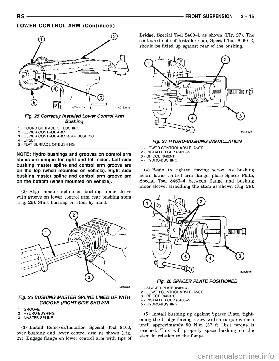
(2) Align master spline on bushing inner sleeve
with groove on lower control arm rear bushing stem
(Fig. 26). Start bushing on stem by hand.
(3) Install Remover/Installer, Special Tool 8460,
over bushing and lower control arm as shown (Fig.
27). Engage flange on lower control arm with tips ofBridge, Special Tool 8460±1 as shown (Fig. 27). The
contoured side of Installer Cup, Special Tool 8460±2,
should be fitted up against rear of the bushing.
(4) Begin to tighten forcing screw. As bushing
nears lower control arm flange, place Spacer Plate,
Special Tool 8460±4 between flange and bushing
inner sleeve, straddling the stem as shown (Fig. 28).
(5) Install bushing up against Spacer Plate, tight-
ening the bridge forcing screw with a torque wrench
until approximately 50 N´m (37 ft. lbs.) torque is
reached. This will properly space bushing on the
stem in relation to the flange.
Fig. 25 Correctly Installed Lower Control Arm
Bushing
1 - ROUND SURFACE OF BUSHING
2 - LOWER CONTROL ARM
3 - LOWER CONTROL ARM REAR BUSHING
4 - UPSET
5 - FLAT SURFACE OF BUSHING
Fig. 26 BUSHING MASTER SPLINE LINED UP WITH
GROOVE (RIGHT SIDE SHOWN)
1 - GROOVE
2 - HYDRO-BUSHING
3 - MASTER SPLINE
Fig. 27 HYDRO-BUSHING INSTALLATION
1 - LOWER CONTROL ARM FLANGE
2 - INSTALLER CUP (8460-2)
3 - BRIDGE (8460-1)
4 - HYDRO-BUSHING
Fig. 28 SPACER PLATE POSITIONED
1 - SPACER PLATE (8460-4)
2 - LOWER CONTROL ARM FLANGE
3 - BRIDGE (8460-1)
4 - INSTALLER CUP (8460-2)
5 - HYDRO-BUSHING
RSFRONT SUSPENSION2-15
LOWER CONTROL ARM (Continued)
Page 59 of 2585

(6) Back off the forcing screw and remove tool.
(7) Install lower control arm on vehicle. (Refer to 2
- SUSPENSION/FRONT/LOWER CONTROL ARM -
INSTALLATION)
INSTALLATION - LOWER CONTROL ARM
(1) Position lower control arm assembly into front
suspension cradle crossmember guiding bushings into
mounting position (Fig. 22).
(2) Install NEW pivot bolt attaching front bushing
of lower control arm to front suspension cradle cross-
member (Fig. 29).Do not tighten or torque pivot
bolt at this time.
(3) Install the reinforcement on the front suspen-
sion cradle crossmember and install the bolts attach-
ing the reinforcement to the cradle crossmember
(Fig. 22). Tighten the M-14 size bolts to a torque of
153 N´m (113 ft. lbs.). Tighten the M-12 size bolts to
a torque of 106 N´m (78 ft. lbs.).
(4) Install the lower control arm rear bushing
retainer bolts through reinforcement on each side of
each lower control arm rear bushing. Tighten these
M-10 size bolts to a torque of 61 N´m (45 ft. lbs.).
(5) Install the two bolts and bushings attaching
the reinforcement and rear of cradle crossmember to
body of vehicle (Fig. 22). Tighten bolts to a torque of
163 N´m (120 ft. lbs.).
(6) Install the power steering cooler (Fig. 21).
Tighten bolts to a torque of 11 N´m (100 in. lbs.).
(7) Reinstall steering knuckle, brake rotor and cal-
iper. (Refer to 2 - SUSPENSION/FRONT/KNUCKLE
- INSTALLATION)CAUTION: When locating jack stands under lower
control arms, do not place the jack stands under
the ball joints (Fig. 30).
(8) Position jack stands under the lower control
arms as close to the ball joints as possible (Fig. 30).
Lower the vehicle onto the jack stands until the jack
stands are supporting the total weight of the vehicle.
(9) Tighten front lower control arm pivot bolt to a
torque of 183 N´m (135 ft. lbs.).
(10) Install the wheel and tire assembly. Install
and tighten the wheel mounting stud nuts in proper
sequence until all nuts are torqued to half specifica-
tion. Then repeat the tightening sequence to the full
specified torque of 135 N´m (100 ft. lbs.).
(11) Raise vehicle, remove jack stands and lower
vehicle to the ground.
(12) Perform front wheel alignment as necessary.
(Refer to 2 - SUSPENSION/WHEEL ALIGNMENT -
STANDARD PROCEDURE)
STABILIZER BAR
DESCRIPTION
The stabilizer bar interconnects both front struts of
the vehicle and is attached to the front crossmember
(Fig. 1).
Attachment of the stabilizer bar to the front cross-
member is through 2 rubber-isolator cushion bush-
ings and retainers. A double ball jointed stabilizer
bar link is used to attach each end of the stabilizer
bar to the front strut assemblies. All parts of the sta-
bilizer bar are replaceable as individual components.
Fig. 29 Lower Control Arm Bushing Pivot Bolt
Correctly Installed
1 - PIVOT BOLT
2 - LOWER CONTROL ARM
3 - FRONT SUSPENSION CRADLE CROSSMEMBER
Fig. 30 Jack Stands Supporting Vehicle Weight
1 - LOWER CONTROL ARMS
2 - BALL JOINT
3 - JACK STANDS
4 - BALL JOINT
2 - 16 FRONT SUSPENSIONRS
LOWER CONTROL ARM (Continued)
Page 60 of 2585

The stabilizer bar to front crossmember cushion
bushings are split for easy removal and installation.
The split in the bushings should be positioned toward
the rear of the vehicle, with the square corner facing
down, when the stabilizer bar is installed.
OPERATION
Jounce and rebound movements affecting one
wheel are partially transmitted to the opposite wheel
of the vehicle through the stabilizer bar. This helps
to minimize the body roll of the vehicle during sus-
pension movement.
Connecting the stabilizer bar links to the strut
assemblies helps reduce the fore-and-aft rate of the
stabilizer bar from the rest of the front suspension.
REMOVAL
(1) Raise vehicle. (Refer to LUBRICATION &
MAINTENANCE/HOISTING - STANDARD PROCE-
DURE)
(2) Remove the bolts fastening the power steering
cooler to the front suspension cradle crossmember
reinforcement (Fig. 31).
(3) Remove the lower control arm rear bushing
retainer bolts located on each side of each lower con-
trol arm rear bushing.
NOTE: The bolts fastening the cradle crossmember
reinforcement are of two different thread sizes. Note
the location of the various sizes.(4) Remove the bolts attaching the cradle cross-
member reinforcement to the front suspension cradle
crossmember (Fig. 32). Remove the 2 bolts fastening
the reinforcement and rear of cradle crossmember to
the body of the vehicle. Remove the reinforcement.
Fig. 31 Power Steering Cooler
1 - CRADLE CROSSMEMBER REINFORCEMENT
2 - POWER STEERING COOLER
Fig. 32 Cradle Crossmember Reinforcement
Attachment
1 - STEERING GEAR
2 - RIGHT LOWER CONTROL ARM
3 - LEFT LOWER CONTROL ARM
4 - CRADLE CROSSMEMBER REINFORCEMENT
5 - REAR CRADLE CROSSMEMBER ISOLATOR BUSHING
6 - STABILIZER BAR
7 - CRADLE CROSSMEMBER
RSFRONT SUSPENSION2-17
STABILIZER BAR (Continued)