volt CHRYSLER VOYAGER 2004 Service Manual
[x] Cancel search | Manufacturer: CHRYSLER, Model Year: 2004, Model line: VOYAGER, Model: CHRYSLER VOYAGER 2004Pages: 2585, PDF Size: 62.54 MB
Page 41 of 2585
WARNING: DO NOT ALLOW JUMPER CABLE
CLAMPS TO TOUCH EACH OTHER WHEN CON-
NECTED TO A BOOSTER SOURCE.
WARNING: DO NOT USE OPEN FLAME NEAR BAT-
TERY
WARNING: REMOVE METALLIC JEWELRY WORN
ON HANDS OR WRISTS TO AVOID INJURY BY
ACCIDENTAL ARCING OF BATTERY CURRENT.
WARNING: WHEN USING A HIGH OUTPUT BOOST-
ING DEVICE, DO NOT ALLOW BATTERY VOLTAGE
TO EXCEED 16 VOLTS.
WARNING: REFER TO INSTRUCTIONS PROVIDED
WITH DEVICE BEING USED.
CAUTION: DO NOT ATTEMPT TO PUSH OR TOW
THE VEHICLE TO START IT. THE VEHICLE CANNOT
BE STARTED THIS WAY. PUSHING WITH ANOTHER
VEHICLE MAY DAMAGE THE TRANSAXLE OR THE
REAR OF THE VEHICLE.
(1) Raise hood on disabled vehicle and visually
inspect engine compartment for:
²Battery cable clamp condition, clean if necessary.
²Frozen battery.
²Clear or bright color test indicator, if equipped.
²Generator drive belt condition and tension.
²Fuel fumes or leakage, correct if necessary.
CAUTION: If the cause of starting problem on dis-
abled vehicle is severe, damage to booster vehicle
charging system can result.
(2) When using another vehicle as a booster
source, park the booster vehicle within cable reach.
Turn off all accessories, set the parking brake, place
the automatic transmission in PARK or the manual
transmission in NEUTRAL and turn the ignition
OFF.
(3) On disabled vehicle, place gear selector in park
or neutral and set park brake. Turn off all accesso-
ries.
(4) Connect jumper cables to booster battery. RED
clamp to positive terminal (+). BLACK clamp to neg-
ative terminal (-). DO NOT allow clamps at opposite
end of cables to touch, electrical arc will result.
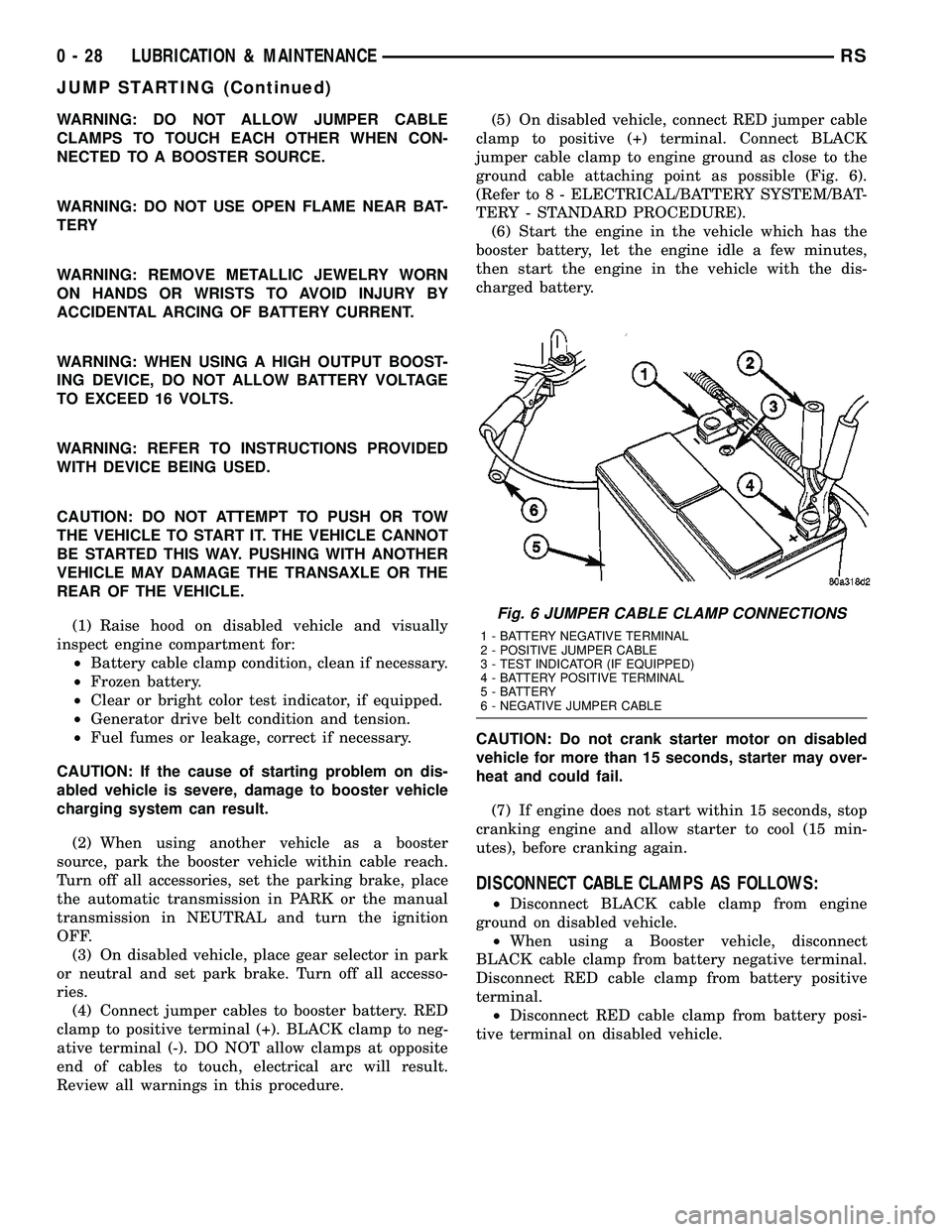
Review all warnings in this procedure.(5) On disabled vehicle, connect RED jumper cable
clamp to positive (+) terminal. Connect BLACK
jumper cable clamp to engine ground as close to the
ground cable attaching point as possible (Fig. 6).
(Refer to 8 - ELECTRICAL/BATTERY SYSTEM/BAT-
TERY - STANDARD PROCEDURE).
(6) Start the engine in the vehicle which has the
booster battery, let the engine idle a few minutes,
then start the engine in the vehicle with the dis-
charged battery.
CAUTION: Do not crank starter motor on disabled
vehicle for more than 15 seconds, starter may over-
heat and could fail.
(7) If engine does not start within 15 seconds, stop
cranking engine and allow starter to cool (15 min-
utes), before cranking again.
DISCONNECT CABLE CLAMPS AS FOLLOWS:
²Disconnect BLACK cable clamp from engine
ground on disabled vehicle.
²When using a Booster vehicle, disconnect
BLACK cable clamp from battery negative terminal.
Disconnect RED cable clamp from battery positive
terminal.
²Disconnect RED cable clamp from battery posi-
tive terminal on disabled vehicle.
Fig. 6 JUMPER CABLE CLAMP CONNECTIONS
1 - BATTERY NEGATIVE TERMINAL
2 - POSITIVE JUMPER CABLE
3 - TEST INDICATOR (IF EQUIPPED)
4 - BATTERY POSITIVE TERMINAL
5 - BATTERY
6 - NEGATIVE JUMPER CABLE
0 - 28 LUBRICATION & MAINTENANCERS
JUMP STARTING (Continued)
Page 225 of 2585
CAUTION
CAUTIONS
The ABS uses an electronic control module, the
CAB. This module is designed to withstand normal
current draws associated with vehicle operation.
Care must be taken to avoid overloading the CAB
circuits.
CAUTION: In testing for open or short circuits, do
not ground or apply voltage to any of the circuits
unless instructed to do so for a diagnostic proce-
dure.
CAUTION: These circuits should only be tested
using a high impedance multi-meter or the DRBIIIT
scan tool as described in this section. Power
should never be removed or applied to any control
module with the ignition in the ON position. Before
removing or connecting battery cables, fuses, or
connectors, always turn the ignition to the OFF
position.
CAUTION: The CAB 24-way connector should never
be connected or disconnected with the ignition
switch in the ON position.
CAUTION: This vehicle utilizes active wheel speed
sensors. Do not apply voltage to wheel speed sen-
sors at any time.
CAUTION: Use only factory wiring harnesses. Do
not cut or splice wiring to the brake circuits. The
addition of aftermarket electrical equipment (car
phone, radar detector, citizen band radio, trailer
lighting, trailer brakes, etc.) on a vehicle equipped
with antilock brakes may affect the function of the
antilock brake system.
CAUTION: When performing any service procedure
on a vehicle equipped with ABS, do not apply a
12-volt power source to the ground circuit of the
pump motor in the HCU. Doing this will damage the
pump motor and will require replacement of the
entire HCU.
CAUTION: An attempt to remove or disconnect cer-
tain system components may result in improper
system operation. Only those components with
approved removal and installation procedures in
this manual should be serviced.CAUTION: If welding work is to be performed on the
vehicle, using an electric arc welder, the CAB con-
nector should be disconnected during the welding
operation.
CAUTION: Many components of the ABS System
are not serviceable and must be replaced as an
assembly. Do not disassemble any component
which is not designed to be serviced.
CAUTION: Only the recommended jacking or hoist-
ing positions for this vehicle are to be used when-
ever it is necessary to lift a vehicle. Failure to raise
a vehicle from the recommended locations could
result in lifting a vehicle by the hydraulic control
unit mounting bracket. Lifting a vehicle by the
hydraulic control unit mounting bracket will result
in damage to the mounting bracket and the hydrau-
lic control unit.
CAUTION: Brake fluid will damage painted surfaces.
If brake fluid is spilled on any painted surface,
wash off with water immediately.
STANDARD PROCEDURE - ANTILOCK BRAKE
SYSTEM BLEEDING
The base brake's hydraulic system must be bled
anytime air enters the hydraulic system. The ABS
though, particularly the ICU (HCU), should only be
bled when the HCU is replaced or removed from the
vehicle. The ABS must always be bled anytime it is
suspected that the HCU has ingested air. Under
most circumstances that require the bleeding of the
brakes hydraulic system, only the base brake
hydraulic system needs to be bled.
It is important to note that excessive air in the
brake system will cause a soft or spongy feeling
brake pedal.
During the brake bleeding procedure, be sure the
brake fluid level remains close to the FULL level in
the master cylinder fluid reservoir. Check the fluid
level periodically during the bleeding procedure and
add DOT 3 brake fluid as required.
The ABS must be bled as two independent braking
systems. The non-ABS portion of the brake system
with ABS is to be bled the same as any non-ABS sys-
tem.
The ABS portion of the brake system must be bled
separately. Use the following procedure to properly
bleed the brake hydraulic system including the ABS.
5 - 78 BRAKES - ABSRS
BRAKES - ABS (Continued)
Page 237 of 2585
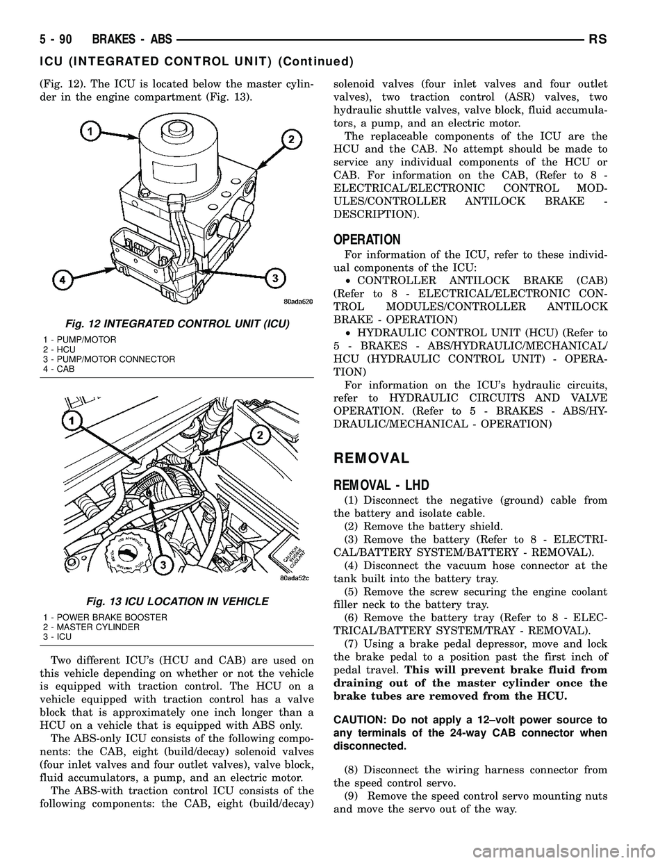
(Fig. 12). The ICU is located below the master cylin-
der in the engine compartment (Fig. 13).
Two different ICU's (HCU and CAB) are used on
this vehicle depending on whether or not the vehicle
is equipped with traction control. The HCU on a
vehicle equipped with traction control has a valve
block that is approximately one inch longer than a
HCU on a vehicle that is equipped with ABS only.
The ABS-only ICU consists of the following compo-
nents: the CAB, eight (build/decay) solenoid valves
(four inlet valves and four outlet valves), valve block,
fluid accumulators, a pump, and an electric motor.
The ABS-with traction control ICU consists of the
following components: the CAB, eight (build/decay)solenoid valves (four inlet valves and four outlet
valves), two traction control (ASR) valves, two
hydraulic shuttle valves, valve block, fluid accumula-
tors, a pump, and an electric motor.
The replaceable components of the ICU are the
HCU and the CAB. No attempt should be made to
service any individual components of the HCU or
CAB. For information on the CAB, (Refer to 8 -
ELECTRICAL/ELECTRONIC CONTROL MOD-
ULES/CONTROLLER ANTILOCK BRAKE -
DESCRIPTION).
OPERATION
For information of the ICU, refer to these individ-
ual components of the ICU:
²CONTROLLER ANTILOCK BRAKE (CAB)
(Refer to 8 - ELECTRICAL/ELECTRONIC CON-
TROL MODULES/CONTROLLER ANTILOCK
BRAKE - OPERATION)
²HYDRAULIC CONTROL UNIT (HCU) (Refer to
5 - BRAKES - ABS/HYDRAULIC/MECHANICAL/
HCU (HYDRAULIC CONTROL UNIT) - OPERA-
TION)
For information on the ICU's hydraulic circuits,
refer to HYDRAULIC CIRCUITS AND VALVE
OPERATION. (Refer to 5 - BRAKES - ABS/HY-
DRAULIC/MECHANICAL - OPERATION)
REMOVAL
REMOVAL - LHD
(1) Disconnect the negative (ground) cable from
the battery and isolate cable.
(2) Remove the battery shield.
(3) Remove the battery (Refer to 8 - ELECTRI-
CAL/BATTERY SYSTEM/BATTERY - REMOVAL).
(4) Disconnect the vacuum hose connector at the
tank built into the battery tray.
(5) Remove the screw securing the engine coolant
filler neck to the battery tray.
(6) Remove the battery tray (Refer to 8 - ELEC-
TRICAL/BATTERY SYSTEM/TRAY - REMOVAL).
(7) Using a brake pedal depressor, move and lock
the brake pedal to a position past the first inch of
pedal travel.This will prevent brake fluid from
draining out of the master cylinder once the
brake tubes are removed from the HCU.
CAUTION: Do not apply a 12±volt power source to
any terminals of the 24-way CAB connector when
disconnected.
(8) Disconnect the wiring harness connector from
the speed control servo.
(9) Remove the speed control servo mounting nuts
and move the servo out of the way.
Fig. 12 INTEGRATED CONTROL UNIT (ICU)
1 - PUMP/MOTOR
2 - HCU
3 - PUMP/MOTOR CONNECTOR
4 - CAB
Fig. 13 ICU LOCATION IN VEHICLE
1 - POWER BRAKE BOOSTER
2 - MASTER CYLINDER
3 - ICU
5 - 90 BRAKES - ABSRS
ICU (INTEGRATED CONTROL UNIT) (Continued)
Page 239 of 2585
(2) Using a brake pedal depressor, move and lock
the brake pedal to a position past the first inch of
pedal travel.This will prevent brake fluid from
draining out of the master cylinder when the
brake tubes are removed from the HCU.
(3) Raise vehicle. (Refer to LUBRICATION &
MAINTENANCE/HOISTING - STANDARD PROCE-
DURE)
(4) Remove the routing clip attaching the ICU wir-
ing harness to the ICU mounting bracket (Fig. 17).
CAUTION: Do not apply a 12 volt power source to
any terminals of the HCU connector when discon-
nected.
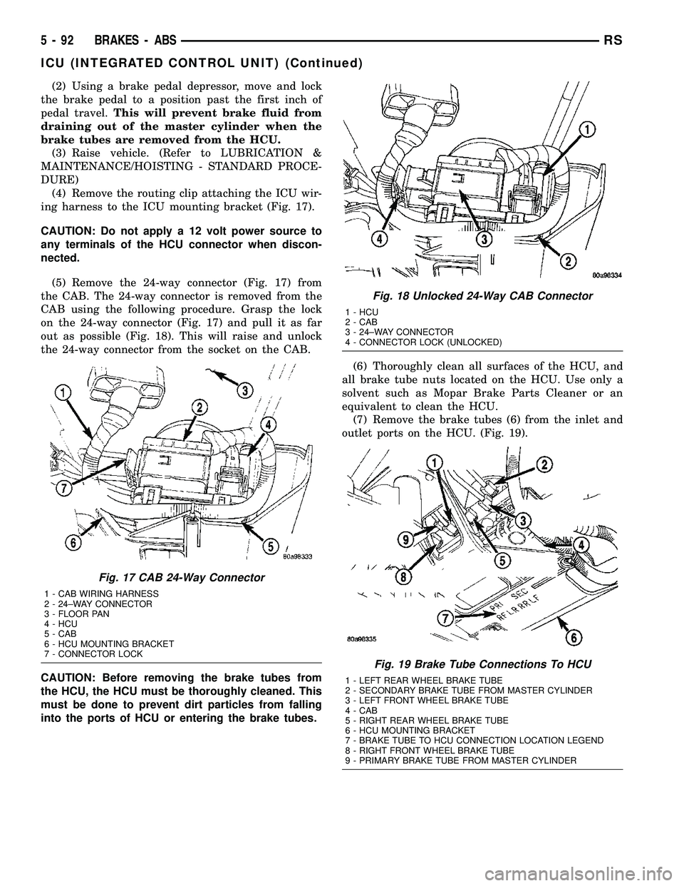
(5) Remove the 24-way connector (Fig. 17) from
the CAB. The 24-way connector is removed from the
CAB using the following procedure. Grasp the lock
on the 24-way connector (Fig. 17) and pull it as far
out as possible (Fig. 18). This will raise and unlock
the 24-way connector from the socket on the CAB.
CAUTION: Before removing the brake tubes from
the HCU, the HCU must be thoroughly cleaned. This
must be done to prevent dirt particles from falling
into the ports of HCU or entering the brake tubes.(6) Thoroughly clean all surfaces of the HCU, and
all brake tube nuts located on the HCU. Use only a
solvent such as Mopar Brake Parts Cleaner or an
equivalent to clean the HCU.
(7) Remove the brake tubes (6) from the inlet and
outlet ports on the HCU. (Fig. 19).
Fig. 17 CAB 24-Way Connector
1 - CAB WIRING HARNESS
2 - 24±WAY CONNECTOR
3 - FLOOR PAN
4 - HCU
5 - CAB
6 - HCU MOUNTING BRACKET
7 - CONNECTOR LOCK
Fig. 18 Unlocked 24-Way CAB Connector
1 - HCU
2 - CAB
3 - 24±WAY CONNECTOR
4 - CONNECTOR LOCK (UNLOCKED)
Fig. 19 Brake Tube Connections To HCU
1 - LEFT REAR WHEEL BRAKE TUBE
2 - SECONDARY BRAKE TUBE FROM MASTER CYLINDER
3 - LEFT FRONT WHEEL BRAKE TUBE
4 - CAB
5 - RIGHT REAR WHEEL BRAKE TUBE
6 - HCU MOUNTING BRACKET
7 - BRAKE TUBE TO HCU CONNECTION LOCATION LEGEND
8 - RIGHT FRONT WHEEL BRAKE TUBE
9 - PRIMARY BRAKE TUBE FROM MASTER CYLINDER
5 - 92 BRAKES - ABSRS
ICU (INTEGRATED CONTROL UNIT) (Continued)
Page 357 of 2585

for checking coolant level and adjusting level at
atmospheric pressure without removing the radiator
pressure cap. It also provides some reserve coolant to
cover deaeration, evaporation, or boiling losses.
DIAGNOSIS AND TESTING - COOLANT
RECOVERY SYSTEM
The cooling system is closed and designed to main-
tain coolant level to the top of the radiator.
(1) With the engineoffand cooling systemnot
under pressure, drain several ounces of coolant from
the radiator draincock while observing the coolant
recovery container. Coolant level in the container
should drop.
(2) Remove the radiator pressure cap. The coolant
level should be full to the top radiator neck. If not,
and the coolant level in the container is at or above
the MIN mark, there is an air leak in the coolant
recovery system.
(3) Check hose and hose connections to the con-
tainer, radiator filler neck or the pressure cap seal to
the radiator filler neck for leaks.
REMOVAL
(1) Raise the vehicle on hoist.
(2) Remove the lower attaching screws (Fig. 2).
(3) Lower the vehicle.
(4) Remove the upper attaching screw (Fig. 2).
(5) Disconnect recovery hose from container (Fig.
2).
(6) Remove the recovery container.
INSTALLATION
(1) Connect the recovery hose to container (Fig. 2).
(2) Position the recovery container on the frame
rail (Fig. 2).
(3) Install the upper attaching screw and tighten
to 7 N´m (60 in. lbs.) (Fig. 2).
(4) Raise the vehicle on hoist.
(5) Install the lower attaching screws and tighten
to 8.5 N´m (75 in. lbs.) (Fig. 2).
(6) Lower the vehicle.
(7) Add coolant to container as necessary. (Refer to
7 - COOLING - STANDARD PROCEDURE)
ENGINE BLOCK HEATER
DESCRIPTION
The engine block heater is available as an optional
accessory on all models. The heater is operated by
ordinary house current (110 Volt A.C.) through a
power cord located behind the radiator grille. This
provides easier engine starting and faster warm-up
when vehicle is operated in areas having extremely
low temperatures. The heater is mounted in a core
hole (in place of a core hole plug) in the engine block,
with the heating element immersed in coolant.
OPERATION
The block heater element is submerged in the cool-
ing system's coolant. When electrical power (110 volt
A.C.) is applied to the element, it creates heat. This
heat is transferred to the engine coolant. This pro-
vides easier engine starting and faster warm-up
when vehicle is operated in areas having extremely
low temperatures.
DIAGNOSIS AND TESTING - ENGINE BLOCK
HEATER TESTING
If unit does not operate, trouble can be in either
the power cord or the heater element. Test power
cord for continuity with a 110-volt voltmeter or 110-
volt test light; test heater element continuity with an
ohmmeter or 12-volt test light.
REMOVAL
(1) Drain coolant from radiator and cylinder block.
(Refer to 7 - COOLING - STANDARD PROCEDURE)
(2) Disconnect the power cord plug from heater.
(3) Loosen screw in center of heater. Remove the
heater assembly.
INSTALLATION
(1) Clean block core hole and heater seat.
(2) Insert heater assembly with element loop posi-
tionedupward.
Fig. 2 Coolant Recovery Container
1 - UPPER BOLT ATTACHING TO BATTERY TRAY
2 - COOLANT RECOVERY CONTAINER
3 - UPPER BOLT
4 - HOSE
5 - LOWER BOLT (QTY. 2)
6 - LEFT SIDE FRAME RAIL
7 - 20 ENGINERS
COOLANT RECOVERY CONTAINER (Continued)
Page 367 of 2585

REMOVAL
There are no repairs to be made to the fan or
shroud assembly. If the fan is warped, cracked, or
otherwise damaged, it must be replaced as an assem-
bly (Fig. 21).
(1) Remove the radiator upper crossmember. (Refer
to 23 - BODY/EXTERIOR/GRILLE OPENING REIN-
FORCEMENT - REMOVAL)
(2) Disconnect the radiator fan electrical connec-
tors.
(3) Remove radiator fan(s) retaining screw (Fig.
21).
(4) Remove the radiator fan(s) by lifting upward to
release from mounts.
INSTALLATION
(1) Install the radiator fan(s) into mounts and
attaching clips on the radiator.
(2) Install radiator fan(s) attaching screws (Fig.
21). Tighten to 5 N´m (45 in. lbs.).
(3) Connect the radiator fan(s) electrical connec-
tors.
(4) Install the radiator upper support crossmem-
ber. (Refer to 23 - BODY/EXTERIOR/GRILLE OPEN-
ING REINFORCEMENT - INSTALLATION)
(5) Install the upper radiator mounts to the cross-
member bolts, if removed. Tighten to 8 N´m (70 in.
lbs.).
(6) Install the radiator upper hose to the support
clip (2.4L engine).
RADIATOR FAN RELAY
DESCRIPTION
The radiator fan relay is a solid state type and is
located on the front bumper reinforcment (Fig. 22).
Refer to WIRING DIAGRAMS for a circuit sche-
matic.
OPERATION
The solid state radiator fan relay is controlled by
the Powertrain Control Module (PCM) by way of a
Pulse Width Modulated (PWM) signal. The relay con-
trol circuit supplies a 12 volt signal to the PCM. The
PCM then pulses the ground circuit to achieve fan on
time. The relay provides a voltage to the fan motors
which is proportional to the pulse width it receives
from the PCM. The duty cycle ranges from 30% for
low speed operation, then ramps-up to 100% for high
speed operation. This fan control system provides
infinitely variable fan speeds, allowing for improved
fan noise, A/C performance, better engine cooling,
and additional vehicle power.
To control operation of the relay, the PCM looks at
inputs from:
²Engine coolant temperature
²A/C pressure transducer
²Ambient temperature from the body controller
²Vehicle speed
²Transmission oil temperature
The PCM uses these inputs to determine when the
fan should operate and at what speed. For further
information on fan operation, (Refer to 7 - COOL-
ING/ENGINE/RADIATOR FAN - OPERATION).
REMOVAL
(1) Open hood.
(2) Disconnect and isolate the battery negative
cable.
(3) Remove the radiator crossmember to front fas-
cia closure panel.
(4) Disconnect the relay electrical connector (Fig.
22).
(5) Remove the rivet attaching the relay to the
front bumper beam (Fig. 22).
(6) Remove the relay.
INSTALLATION
CAUTION: The relay mounting location is designed
to dissipate heat. Ensure the relay is securely
attached to prevent relay ªthermalº shutdown and
relay damage, resulting in possible engine over-
heating.
(1) Position relay and install a new rivet (Fig. 22).
(2) Connect electrical connector to relay.
Fig. 21 Radiator Fans
1 - SCREWS - RADIATOR FAN ATTACHING
2 - RADIATOR FAN - RIGHT
3 - MOUNT - RIGHT RADIATOR FAN
4 - CLIPS - RADIATOR FAN LOWER
5 - MOUNT - LEFT RADIATOR FAN
6 - RADIATOR FAN - LEFT
7 - 30 ENGINERS
RADIATOR FAN (Continued)
Page 377 of 2585

dures, further details on wire harness routing and
retention, as well as pin-out and location views for
the various wire harness connectors, splices, and
grounds.
OPERATION
Operating instructions for the factory installed
audio systems can be found in the Owner's Manual
provided with this vehicle.
DIAGNOSIS AND TESTING - AUDIO
Any diagnosis of the Audio system should
begin with the use of the DRB IIItdiagnostic
tool. For information on the use of the DRB
IIIt, refer to the appropriate Diagnostic Service
Manual.Refer to the appropriate wiring information. The
wiring information includes wiring diagrams, proper
wire and connector repair procedures, details of wire
harness routing and retention, connector pin-out
information and location views for the various wire
harness connectors, splices and grounds.
WARNING: ON VEHICLES EQUIPPED WITH AIR-
BAGS, REFER TO ELECTRICAL, RESTRAINTS
BEFORE ATTEMPTING ANY STEERING WHEEL,
STEERING COLUMN, OR INSTRUMENT PANEL
COMPONENT DIAGNOSIS OR SERVICE. FAILURE
TO TAKE THE PROPER PRECAUTIONS COULD
RESULT IN ACCIDENTAL AIRBAG DEPLOYMENT
AND POSSIBLE PERSONAL INJURY.
AUDIO SYSTEM DIAGNOSIS
CONDITION POSSIBLE CAUSE CORRECTION
NO AUDIO. 1. FUSE FAULTY. 1. CHECK RADIO FUSES IN FUSE BLOCK MODULE.
REPLACE FUSES, IF REQUIRED.
2. RADIO CONNECTOR
FAULTY.2. CHECK FOR LOOSE OR CORRODED RADIO CONNECTOR.
REPAIR, IF REQUIRED.
3. WIRING FAULTY. 3. CHECK FOR BATTERY VOLTAGE AT RADIO CONNECTOR.
REPAIR WIRING, IF REQUIRED.
4. GROUND FAULTY. 4. CHECK FOR CONTINUITY BETWEEN RADIO CHASSIS AND
A KNOWN GOOD GROUND. THERE SHOULD BE
CONTINUITY. REPAIR GROUND, IF REQUIRED.
5. RADIO FAULTY. 5. EXCHANGE OR REPLACE RADIO, IF REQUIRED.
6. SPEAKERS FAULTY. 6. SEE SPEAKER DIAGNOSIS, IN THIS GROUP.
NO DISPLAY. 1. FUSE FAULTY. 1. CHECK RADIO FUSES IN FUSE BLOCK MODULE.
REPLACE FUSES, IF REQUIRED.
2. RADIO CONNECTOR
FAULTY.2. CHECK FOR LOOSE OR CORRODED RADIO CONNECTOR.
REPAIR, IF REQUIRED.
3. WIRING FAULTY. 3. CHECK FOR BATTERY VOLTAGE AT RADIO CONNECTOR.
REPAIR WIRING, IF REQUIRED.
4. GROUND FAULTY. 4. CHECK FOR CONTINUITY BETWEEN RADIO CHASSIS AND
A KNOWN GOOD GROUND. THERE SHOULD BE
CONTINUITY. REPAIR GROUND, IF REQUIRED.
5. RADIO FAULTY. 5. EXCHANGE OR REPLACE RADIO, IF REQUIRED.
8A - 2 AUDIORS
AUDIO/VIDEO (Continued)
Page 378 of 2585
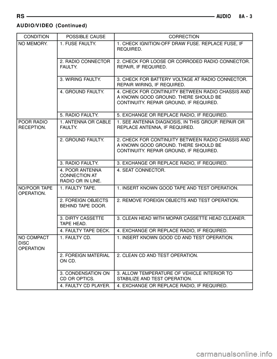
CONDITION POSSIBLE CAUSE CORRECTION
NO MEMORY. 1. FUSE FAULTY. 1. CHECK IGNITION-OFF DRAW FUSE. REPLACE FUSE, IF
REQUIRED.
2. RADIO CONNECTOR
FAULTY.2. CHECK FOR LOOSE OR CORRODED RADIO CONNECTOR.
REPAIR, IF REQUIRED.
3. WIRING FAULTY. 3. CHECK FOR BATTERY VOLTAGE AT RADIO CONNECTOR.
REPAIR WIRING, IF REQUIRED.
4. GROUND FAULTY. 4. CHECK FOR CONTINUITY BETWEEN RADIO CHASSIS AND
A KNOWN GOOD GROUND. THERE SHOULD BE
CONTINUITY. REPAIR GROUND, IF REQUIRED.
5. RADIO FAULTY. 5. EXCHANGE OR REPLACE RADIO, IF REQUIRED.
POOR RADIO
RECEPTION.1. ANTENNA OR CABLE
FAULTY.1. SEE ANTENNA DIAGNOSIS, IN THIS GROUP. REPAIR OR
REPLACE ANTENNA, IF REQUIRED.
2. GROUND FAULTY. 2. CHECK FOR CONTINUITY BETWEEN RADIO CHASSIS AND
A KNOWN GOOD GROUND. THERE SHOULD BE
CONTINUITY. REPAIR GROUND, IF REQUIRED.
3. RADIO FAULTY. 3. EXCHANGE OR REPLACE RADIO, IF REQUIRED.
4. POOR ANTENNA
CONNECTION AT
RADIO OR IN LINE.4. SEAT CONNECTOR.
NO/POOR TAPE
OPERATION.1. FAULTY TAPE. 1. INSERT KNOWN GOOD TAPE AND TEST OPERATION.
2. FOREIGN OBJECTS
BEHIND TAPE DOOR.2. REMOVE FOREIGN OBJECTS AND TEST OPERATION.
3. DIRTY CASSETTE
TAPE HEAD.3. CLEAN HEAD WITH MOPAR CASSETTE HEAD CLEANER.
4. FAULTY TAPE DECK. 4. EXCHANGE OR REPLACE RADIO, IF REQUIRED.
NO COMPACT
DISC
OPERATION1. FAULTY CD. 1. INSERT KNOWN GOOD CD AND TEST OPERATION.
2. FOREIGN MATERIAL
ON CD.2. CLEAN CD AND TEST OPERATION.
3. CONDENSATION ON
CD OR OPTICS.3. ALLOW TEMPERATURE OF VEHICLE INTERIOR TO
STABILIZE AND TEST OPERATION.
4. FAULTY CD PLAYER. 4. EXCHANGE OR REPLACE RADIO, IF REQUIRED.
RSAUDIO8A-3
AUDIO/VIDEO (Continued)
Page 381 of 2585

(10) Remove antenna mast from antenna base
(Fig. 3).
(11) Using cap nut tool, remove cap nut holding
antenna base to front fender (Fig. 4).(12) Remove antenna base from under front
fender.
INSTALLATION
(1) Install antenna base to underside of front
fender.
(2) Install cap nut holding antenna base to front
fender.
(3) Install antenna mast to antenna base.
(4) Install front wheelhouse splash shield.
(5) Install front wheel.
(6) Lower vehicle.
(7) Push antenna cable through opening in hinge
pillar.
(8) Insert rubber grommet into door hinge pillar.
(9) Install kick panel.
(10) Connect antenna cable connector to extension
cable.
(11) Install glove box to instrument panel.
(12) Connect the battery negative cable.
ANTENNA MODULE - EXPORT
DESCRIPTION
The antenna module is an electromagnetic circuit
component designed to capture and enhance RF
(Radio Frequency) signals in both the AM and FM
broadcast bands. The antenna module is mounted to
the right rear roof rail under the headliner. The mod-
ule is grounded through the mounting bracket and
fastener. The module has a two wire electrical con-
nector that connects to the integral radio antenna,
located on the right rear quarter glass. There is also
an electrical connector for battery voltage and a coax
cable connector.
OPERATION
The antenna module receives both AM and FM
radio signals supplied by the side window integral
radio antenna system and selectively amplifies them.
The amplified signal is then sent through the body
length coax cable to the radio input.
Fig. 3 Antenna Mast
1 - ANTENNA MAST
2 - ADAPTER
3 - CAP NUT
Fig. 4 Antenna Cap Nut
1 - CAP NUT
2 - ANTENNA ADAPTER
3 - TOOL
8A - 6 AUDIORS
ANTENNA BODY AND CABLE (Continued)
Page 382 of 2585

DIAGNOSIS AND TESTING - ANTENNA MODULE - EXPORT
CONDITION POSSIBLE CAUSES CORRECTION
NO AM RECEPTION,
WEAK FM RECEPTION1. Antenna module to antenna
connector open or disconnected.1. Repair open, reconnect
antenna module connector to
glass mounted antenna.
2. Coax open or disconnected. 2. Repair open, reconnect coax.
3. No battery power at antenna
module.3. Check fuse. if okay, repair
open in battery voltage circuit.
NO AM OR FM
RECEPTION1. Coax disconnected at radio. 1. Reconnect coax.
2. Coax shorted to ground. 2. Repair or Replace coax
WEAK OR NO AM/FM
RECEPTION1. Antenna Module faulty. 1. Substitute known good
module. If reception improves,
Antenna Module was faulty.
REMOVAL
(1) Disconnect and isolate the battery negative
cable.
(2) Lower headliner as necessary to access
antenna module (Fig. 5).
(3) Disconnect antenna coax cable lead and electri-
cal harness connector from antenna module.
(4) Disconnect the antenna module connector from
the quarter glass.
(5) Remove the mounting screw and the antenna
module.
INSTALLATION
(1) Install the antenna module and the mounting
fastener.
(2) Connect the antenna connector to the quarter
glass.(3) Connect the antenna lead and electrical con-
nector to the antenna module.
(4) Raise and install headliner.
(5) Connect the battery negative cable.
CD CHANGER
DESCRIPTION
The 6 Disc In-Dash CD Changer (if equipped) is
located in the instrument panel below the radio. The
remote changer does not use a cartridge or magazine
for the CD's. Up to 6 CD's can be directly loaded into
this unit.
OPERATION
Due to its compact design, the CD changer can
carry out only one operation at a time. For example,
you can not load a new disc while playing another at
the same time. Each operation happens sequentially.
The radio unit provides control over all features of
the CD changer with the exception of the CD load
and eject functions, which are controlled by buttons
located on the front of the CD changer. All features
you would expect, such as Disc Up/Down, Track
Up/Down, Random and Scan are controlled by the
radio, which also displays all relevant CD changer
information on the radio display.
The CD changer contains a Eject button, six disc
buttons, an indicator LED for each of the six disc
positions as well as an illuminated disc opening. The
individual LED indicates whether a CD is currently
loaded in that particular chamber of the CD changer.
Pressing the individual button for a particular cham-
ber, then the Eject button will eject a disc currently
present in that chamber. If the chamber is currently
empty, actuating the individual button will position
Fig. 5 ANTENNA MODULE
1 - ANTENNA MODULE
2 - ANTENNA MODULE CONNECTOR
RSAUDIO8A-7
ANTENNA MODULE - EXPORT (Continued)