wheel CHRYSLER VOYAGER 2005 Service Manual
[x] Cancel search | Manufacturer: CHRYSLER, Model Year: 2005, Model line: VOYAGER, Model: CHRYSLER VOYAGER 2005Pages: 2339, PDF Size: 59.69 MB
Page 207 of 2339

ABS PRIMARY HYDRAULIC CIRCUIT AND
SOLENOID VALVE FUNCTION (ABS WITHOUT
TRACTION CONTROL)
The hydraulic diagram (Fig. 7) shows the vehicle in
the ABS braking mode. The diagram shows one
wheel is slipping because the driver is attempting to
stop the vehicle at a faster rate than is allowed by
the surface on which the tires are riding.
²The normally open and normally closed valves
modulate (build/decay) the brake hydraulic pressure
as required.
²The pump/motor is switched on so that the
brake fluid from the low pressure accumulators is
returned to the master cylinder circuits.
²The brake fluid is routed to either the master
cylinder or the wheel brake depending on the posi-
tion of the normally open valve.
Fig. 7 ABS Without Traction Control - Primary Hydraulic Circuit
1 - OUTLET VALVE
2 - PUMP PISTON
3 - PUMP MOTOR (ON)
4 - LOW PRESSURE ACCUMULATOR PRESSURE
5 - LOW PRESSURE ACCUMULATOR
6 - NORMALLY CLOSED VALVE (MODULATING)
7 - TO RIGHT FRONT WHEEL8 - NORMALLY OPEN VALVE (MODULATING)
9 - FROM MASTER CYLINDER
10 - MASTER CYLINDER PRESSURE
11 - CONTROLLED WHEEL PRESSURE
12 - PUMP INTERSTAGE PRESSURE
13 - NOISE DAMPER CHAMBER
5 - 96 BRAKES - ABSRS
HYDRAULIC/MECHANICAL (Continued)
Page 208 of 2339
ABS SECONDARY HYDRAULIC CIRCUIT AND
SOLENOID VALVE FUNCTION (ABS WITHOUT
TRACTION CONTROL)
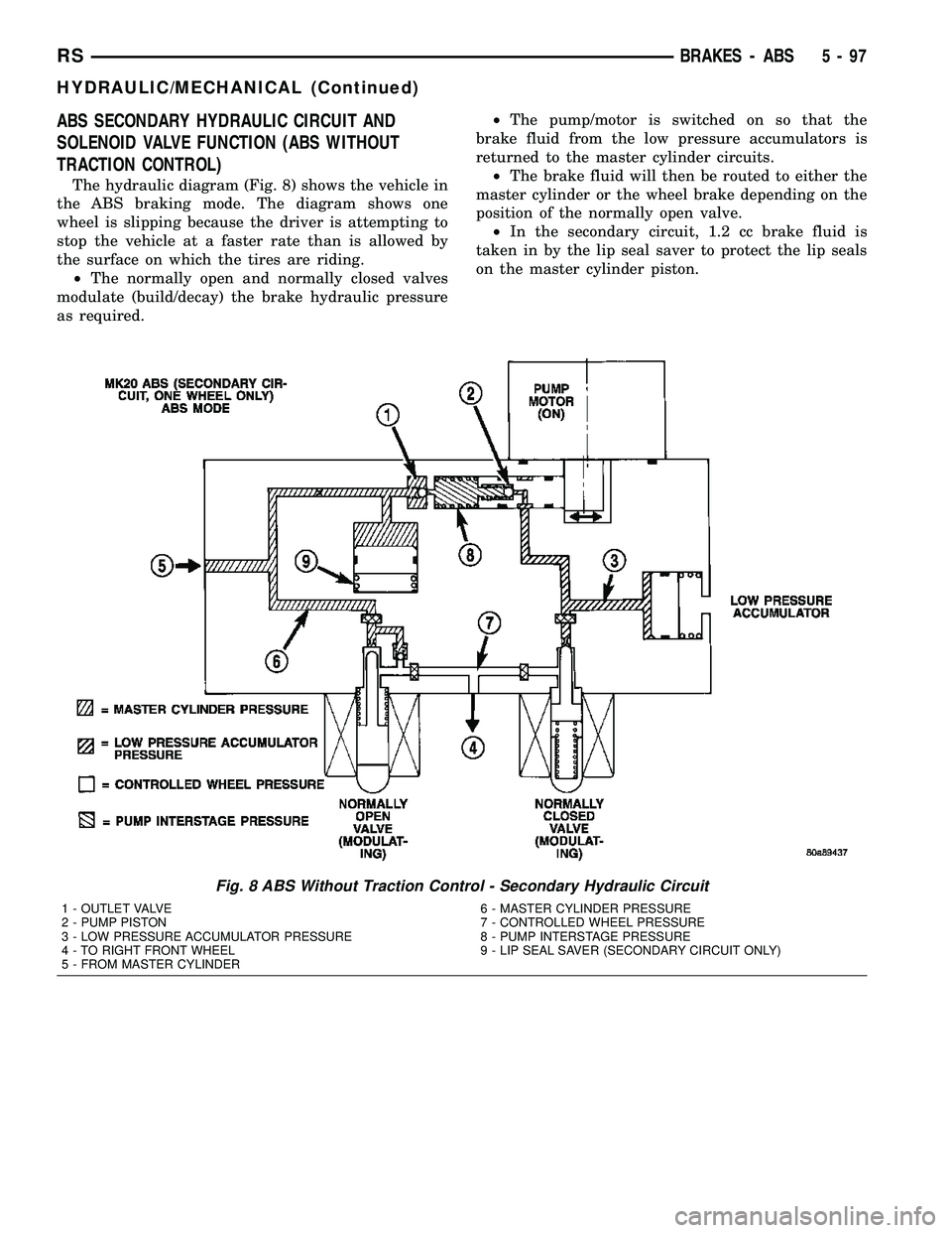
The hydraulic diagram (Fig. 8) shows the vehicle in
the ABS braking mode. The diagram shows one
wheel is slipping because the driver is attempting to
stop the vehicle at a faster rate than is allowed by
the surface on which the tires are riding.
²The normally open and normally closed valves
modulate (build/decay) the brake hydraulic pressure
as required.²The pump/motor is switched on so that the
brake fluid from the low pressure accumulators is
returned to the master cylinder circuits.
²The brake fluid will then be routed to either the
master cylinder or the wheel brake depending on the
position of the normally open valve.
²In the secondary circuit, 1.2 cc brake fluid is
taken in by the lip seal saver to protect the lip seals
on the master cylinder piston.
Fig. 8 ABS Without Traction Control - Secondary Hydraulic Circuit
1 - OUTLET VALVE
2 - PUMP PISTON
3 - LOW PRESSURE ACCUMULATOR PRESSURE
4 - TO RIGHT FRONT WHEEL
5 - FROM MASTER CYLINDER6 - MASTER CYLINDER PRESSURE
7 - CONTROLLED WHEEL PRESSURE
8 - PUMP INTERSTAGE PRESSURE
9 - LIP SEAL SAVER (SECONDARY CIRCUIT ONLY)
RSBRAKES - ABS5-97
HYDRAULIC/MECHANICAL (Continued)
Page 209 of 2339

NORMAL BRAKING HYDRAULIC CIRCUIT,
SOLENOID VALVE, AND SHUTTLE VALVE
FUNCTION (ABS WITH TRACTION CONTROL)
The hydraulic diagram (Fig. 9) shows a vehicle
with traction control in the normal braking mode.
The diagram shows no wheel spin or slip occurring
relative to the speed of the vehicle. The driver is
applying the brake pedal which builds pressure in
the brake hydraulic system to engage the brakes and
stop the vehicle. the hydraulic shuttle valve closes
with every brake pedal application so pressure is not
created at the inlet to the pump/motor.
Fig. 9 ABS With Traction Control - Normal Braking Hydraulic Circuit
1 - OUTLET VALVE
2 - PUMP PISTON
3 - PUMP MOTOR (OFF)
4 - SUCTION VALVE
5 - LOW PRESSURE ACCUMULATOR
6 - NORMALLY CLOSED VALVE (OFF)
7 - TO RIGHT FRONT WHEEL8 - NORMALLY OPEN VALVE (OFF)
9 - NORMALLY OPEN ASR VALVE (OFF)
10 - FROM MASTER CYLINDER
11 - HYDRAULIC SHUTTLE VALVE
12 - MASTER CYLINDER PRESSURE
13 - NOISE DAMPER CHAMBER
5 - 98 BRAKES - ABSRS
HYDRAULIC/MECHANICAL (Continued)
Page 210 of 2339

ABS BRAKING HYDRAULIC CIRCUIT, SOLENOID
VALVE, AND SHUTTLE VALVE FUNCTION (ABS
WITH TRACTION CONTROL)
The hydraulic diagram (Fig. 10) shows the vehicle
in the ABS braking mode. The diagram shows one
wheel is slipping because the driver is attempting to
stop the vehicle at a faster rate than is allowed by
the surface on which the tires are riding.
²The hydraulic shuttle valve closes upon brake
application so that the pump/motor cannot siphon
brake fluid from the master cylinder.²The normally open and normally closed valves
modulate (build/decay) the brake hydraulic pressure
as required.
²The pump/motor is switched on so that the
brake fluid from the low pressure accumulators is
returned to the master cylinder circuits.
²The brake fluid is routed to either the master
cylinder or the wheel brake depending on the posi-
tion of the normally open valve.
Fig. 10 ABS With Traction Control - ABS Braking Hydraulic Circuit
1 - OUTLET VALVE
2 - PUMP PISTON
3 - PUMP MOTOR (ON)
4 - SUCTION VALVE
5 - LOW PRESSURE ACCUMULATOR
6 - NORMALLY CLOSED VALVE (MODULATING)
7 - TO RIGHT FRONT WHEEL
8 - NORMALLY OPEN VALVE (MODULATING)9 - NORMALLY OPEN ASR VALVE (OFF)
10 - FROM MASTER CYLINDER
11 - HYDRAULIC SHUTTLE VALVE
12 - MASTER CYLINDER PRESSURE
13 - CONTROLLED WHEEL PRESSURE
14 - LOW PRESSURE ACCUMULATOR PRESSURE
15 - PUMP INTERSTAGE PRESSURE
16 - NOISE DAMPER CHAMBER
RSBRAKES - ABS5-99
HYDRAULIC/MECHANICAL (Continued)
Page 211 of 2339

ABS TRACTION CONTROL HYDRAULIC CIRCUIT,
SOLENOID VALVE, AND SHUTTLE VALVE
FUNCTION (ABS WITH TRACTION CONTROL)
The hydraulic diagram (Fig. 11) shows the vehicle
in the ABS braking mode. The diagram shows a drive
wheel is spinning and brake pressure is required to
reduce its speed.
²The normally open ASR valve is energized to iso-
late the brake fluid being pumped from the master
cylinder and to isolate the driven wheel.
²The normally open ASR valve bypasses the
pump output back to the master cylinder at a fixed
pressure setting.
²The normally open and normally closed valves
modulate (build/decay) the brake pressure as
required to the spinning wheel.
HCU (HYDRAULIC CONTROL
UNIT)
DESCRIPTION
The hydraulic control unit (HCU) is mounted to
the CAB as part of the ICU (Fig. 22). The HCU con-
trols the flow of brake fluid to the brakes using a
series of valves and accumulators. A pump/motor is
mounted on the HCU to supply build pressure to the
brakes during an ABS stop.
The HCU on a vehicle equipped with ABS and
traction control has a valve block housing that is
approximately 1 inch longer on the low pressure fluid
accumulators side than a HCU on a vehicle that is
equipped with only ABS.
Fig. 11 Traction Control Hydraulic Circuit
1 - OUTLET VALVE
2 - PUMP PISTON
3 - PUMP MOTOR (ON)
4 - LOW PRESSURE ACCUMULATOR PRESSURE
5 - LOW PRESSURE ACCUMULATOR
6 - NORMALLY CLOSED VALVE (MODULATING)
7 - TO RIGHT FRONT WHEEL (SPINNING)
8 - NORMALLY OPEN VALVE (MODULATING)
9 - NORMALLY OPEN ASR VALVE ON (REGULATING)10 - FROM MASTER CYLINDER
11 - HYDRAULIC SHUTTLE VALVE
12 - CONTROLLED WHEEL PRESSURE
13 - SUCTION VALVE
14 - PUMP INTERSTAGE PRESSURE
15 - NOISE DAMPER CHAMBER
16 - MASTER CYLINDER PRESSURE
17 - PUMP PRESSURE
5 - 100 BRAKES - ABSRS
HYDRAULIC/MECHANICAL (Continued)
Page 212 of 2339
For more information, (Refer to 5 - BRAKES/HY-
DRAULIC/MECHANICAL/ICU (INTEGRATED CON-
TROL UNIT) - DESCRIPTION)
OPERATION
For information on the operation of the HCU as a
whole, refer to Hydraulic Circuits And Valve Opera-
tion which can be found elsewhere in this section.
For information on the operation of the components
within the HCU, refer to the following three topics.
VALVES AND SOLENOIDS
The valve block contains four inlet valves and four
outlet valves. The inlet valves are spring-loaded in
the open position and the outlet valves are spring-
loaded in the closed position during normal braking.
The fluid is allowed to flow from the master cylinder
to the wheel brakes.
During an ABS stop, these valves cycle to maintain
the proper slip ratio for each wheel. The inlet valve
closes preventing further pressure increase and the
outlet valve opens to provide a path from the wheel
brake to the HCU accumulators and pump/motor.
This releases (decays) pressure from the wheel brake,
thus releasing the wheel from excessive slippage.
Once the wheel is no longer slipping, the outlet valve
is closed and the inlet valve is opened to reapply
(build) pressure.
On vehicles with traction control, there is an extra
set of valves and solenoids. The ASR valves, mounted
in the HCU valve block, are normally in the open
position and close only when the traction control is
applied.
These isolator valves are used to isolate the rear
(non-driving) wheels of the vehicle from the hydraulic
pressure that the HCU pump/motor is sending to the
front (driving) wheels when traction control is being
applied. The rear brakes need to be isolated from the
master cylinder when traction control is being
applied so the rear wheels do not drag. For more
information, refer to Traction Control System in this
section.
BRAKE FLUID ACCUMULATORS
There are two fluid accumulators in the HCU±one
for the primary hydraulic circuit and one for the sec-
ondary hydraulic circuit. Each hydraulic circuit uses
a 5 cc accumulator.
The fluid accumulators temporarily store brake
fluid that is removed from the wheel brakes during
an ABS cycle. This stored fluid is used by the pump/
motor to provide build pressure for the brake hydrau-
lic system. When the antilock stop is complete, the
accumulators are drained by the pump/motor.
On ABS-only vehicles, there is a mini-accumulator
on the secondary hydraulic circuit that protects the
master cylinder seals during an ABS stop, and there
is a noise dampening chamber on the primary circuit.
On ABS with traction control vehicles, there are
two noise dampening chambers in the HCU.
PUMP/MOTOR
There are two pump assemblies in the HCUÐone
for the primary hydraulic circuit and one for the sec-
ondary hydraulic circuit. Both pumps are driven by a
common electric motor. This DC-type motor is inte-
gral to the HCU and is controlled by the CAB.
The pump/motor provides the extra amount of
brake fluid needed during antilock braking. Brake
fluid is released to the accumulators when the outlet
valve is opened during an antilock stop. The pump
mechanism consists of two opposing pistons operated
by an eccentric camshaft. In operation, one piston
draws fluid from the accumulators, and the opposing
piston pumps fluid to the master cylinder circuits.
When the antilock stop is complete, the pump/motor
drains the accumulators.
The CAB may turn on the pump/motor when an
antilock stop is detected. The pump/motor continues
to run during the antilock stop and is turned off after
the stop is complete. Under some conditions, the
pump/motor runs to drain the accumulators during
the next drive-off.
The pump/motor is not a serviceable item; if it
requires replacement, the HCU must be replaced.
RSBRAKES - ABS5 - 101
HCU (HYDRAULIC CONTROL UNIT) (Continued)
Page 214 of 2339
draining out of the master cylinder once the
brake tubes are removed from the HCU.
CAUTION: Do not apply a 12±volt power source to
any terminals of the 24-way CAB connector when
disconnected.
(8) Disconnect the wiring harness connector from
the speed control servo.
(9) Remove the speed control servo mounting nuts
and move the servo out of the way.
(10) Disconnect the 24±way connector from the
CAB. To disconnect the 24±way connector, grasp the
lock on the 24±way connector and pull it as far up as
possible. This will unlock the 24±way connector from
the socket on the CAB.
CAUTION: Before removing the brake tubes from
the HCU, the HCU must be thoroughly cleaned. This
must be done to prevent dirt particles from falling
into the ports of HCU or entering the brake tubes.
(11) Thoroughly clean all surfaces of the ICU and
brake tube nuts. Use only a solvent such as Mopart
Brake Parts Cleaner or equivalent to clean the ICU.
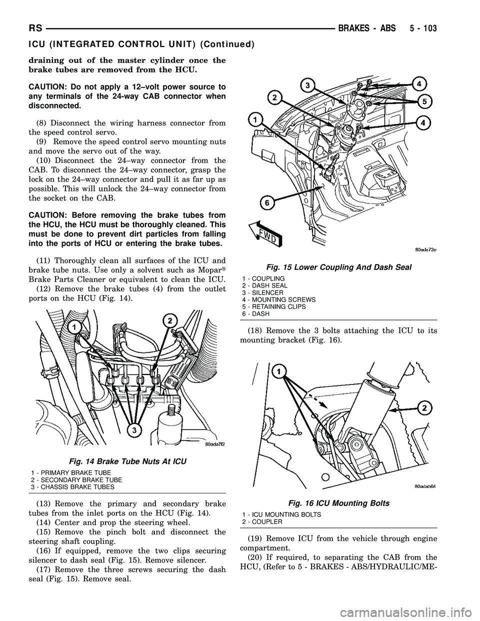
(12) Remove the brake tubes (4) from the outlet
ports on the HCU (Fig. 14).
(13) Remove the primary and secondary brake
tubes from the inlet ports on the HCU (Fig. 14).
(14) Center and prop the steering wheel.
(15) Remove the pinch bolt and disconnect the
steering shaft coupling.
(16) If equipped, remove the two clips securing
silencer to dash seal (Fig. 15). Remove silencer.
(17) Remove the three screws securing the dash
seal (Fig. 15). Remove seal.(18) Remove the 3 bolts attaching the ICU to its
mounting bracket (Fig. 16).
(19) Remove ICU from the vehicle through engine
compartment.
(20) If required, to separating the CAB from the
HCU, (Refer to 5 - BRAKES - ABS/HYDRAULIC/ME-
Fig. 14 Brake Tube Nuts At ICU
1 - PRIMARY BRAKE TUBE
2 - SECONDARY BRAKE TUBE
3 - CHASSIS BRAKE TUBES
Fig. 15 Lower Coupling And Dash Seal
1 - COUPLING
2 - DASH SEAL
3 - SILENCER
4 - MOUNTING SCREWS
5 - RETAINING CLIPS
6 - DASH
Fig. 16 ICU Mounting Bolts
1 - ICU MOUNTING BOLTS
2 - COUPLER
RSBRAKES - ABS5 - 103
ICU (INTEGRATED CONTROL UNIT) (Continued)
Page 215 of 2339
CHANICAL/ICU (INTEGRATED CONTROL UNIT) -
DISASSEMBLY).
REMOVAL - RHD
NOTE: Before proceeding, (Refer to 5 - BRAKES -
WARNING)(Refer to 5 - BRAKES - CAUTION)
(1) Disconnect the negative (ground) cable from
the battery and isolate cable.
(2) Using a brake pedal depressor, move and lock
the brake pedal to a position past the first inch of
pedal travel.This will prevent brake fluid from
draining out of the master cylinder when the
brake tubes are removed from the HCU.
(3) Raise vehicle. (Refer to LUBRICATION &
MAINTENANCE/HOISTING - STANDARD PROCE-
DURE)
(4) Remove the routing clip attaching the ICU wir-
ing harness to the ICU mounting bracket (Fig. 17).
CAUTION: Do not apply a 12 volt power source to
any terminals of the HCU connector when discon-
nected.
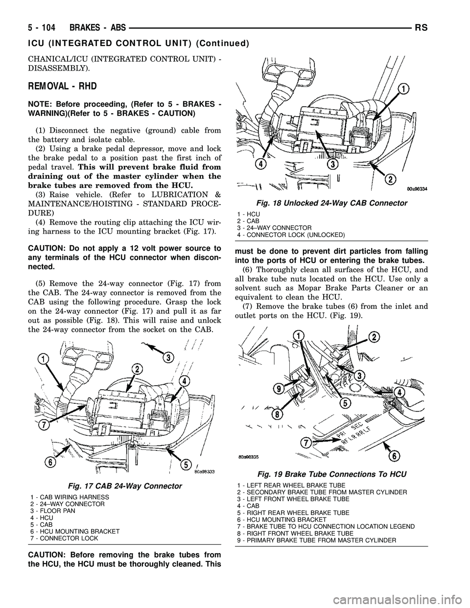
(5) Remove the 24-way connector (Fig. 17) from
the CAB. The 24-way connector is removed from the
CAB using the following procedure. Grasp the lock
on the 24-way connector (Fig. 17) and pull it as far
out as possible (Fig. 18). This will raise and unlock
the 24-way connector from the socket on the CAB.
CAUTION: Before removing the brake tubes from
the HCU, the HCU must be thoroughly cleaned. Thismust be done to prevent dirt particles from falling
into the ports of HCU or entering the brake tubes.
(6) Thoroughly clean all surfaces of the HCU, and
all brake tube nuts located on the HCU. Use only a
solvent such as Mopar Brake Parts Cleaner or an
equivalent to clean the HCU.
(7) Remove the brake tubes (6) from the inlet and
outlet ports on the HCU. (Fig. 19).
Fig. 17 CAB 24-Way Connector
1 - CAB WIRING HARNESS
2 - 24±WAY CONNECTOR
3 - FLOOR PAN
4 - HCU
5 - CAB
6 - HCU MOUNTING BRACKET
7 - CONNECTOR LOCK
Fig. 18 Unlocked 24-Way CAB Connector
1 - HCU
2 - CAB
3 - 24±WAY CONNECTOR
4 - CONNECTOR LOCK (UNLOCKED)
Fig. 19 Brake Tube Connections To HCU
1 - LEFT REAR WHEEL BRAKE TUBE
2 - SECONDARY BRAKE TUBE FROM MASTER CYLINDER
3 - LEFT FRONT WHEEL BRAKE TUBE
4 - CAB
5 - RIGHT REAR WHEEL BRAKE TUBE
6 - HCU MOUNTING BRACKET
7 - BRAKE TUBE TO HCU CONNECTION LOCATION LEGEND
8 - RIGHT FRONT WHEEL BRAKE TUBE
9 - PRIMARY BRAKE TUBE FROM MASTER CYLINDER
5 - 104 BRAKES - ABSRS
ICU (INTEGRATED CONTROL UNIT) (Continued)
Page 217 of 2339
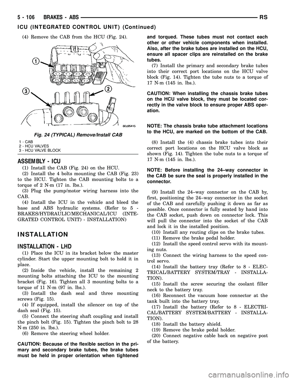
(4) Remove the CAB from the HCU (Fig. 24).
ASSEMBLY - ICU
(1) Install the CAB (Fig. 24) on the HCU.
(2) Install the 4 bolts mounting the CAB (Fig. 23)
to the HCU. Tighten the CAB mounting bolts to a
torque of 2 N´m (17 in. lbs.).
(3) Plug the pump/motor wiring harness into the
CAB.
(4) Install the ICU in the vehicle and bleed the
base and ABS hydraulic systems. (Refer to 5 -
BRAKES/HYDRAULIC/MECHANICAL/ICU (INTE-
GRATED CONTROL UNIT) - INSTALLATION)
INSTALLATION
INSTALLATION - LHD
(1) Place the ICU in its bracket below the master
cylinder. Start the upper mounting bolt to hold it in
place.
(2) Inside the vehicle, install the remaining 2
mounting bolts attaching the ICU to the mounting
bracket (Fig. 16). Tighten all 3 mounting bolts to a
torque of 11 N´m (97 in. lbs.).
(3) Install the dash seal and three mounting
screws (Fig. 15).
(4) If equipped, install the silencer on top of the
dash seal (Fig. 15).
(5) Connect the steering shaft coupling and install
the pinch bolt (Fig. 15). Tighten the pinch bolt to 28
N´m (250 in. lbs.).
(6) Remove the steering wheel holder.
CAUTION: Because of the flexible section in the pri-
mary and secondary brake tubes, the brake tubes
must be held in proper orientation when tightenedand torqued. These tubes must not contact each
other or other vehicle components when installed.
Also, after the brake tubes are installed on the HCU,
ensure all spacer clips are reinstalled on the brake
tubes.
(7) Install the primary and secondary brake tubes
into their correct port locations on the HCU valve
block (Fig. 14). Tighten the tube nuts to a torque of
17 N´m (145 in. lbs.).
CAUTION: When installing the chassis brake tubes
on the HCU valve block, they must be located cor-
rectly in the valve block to ensure proper ABS oper-
ation.
NOTE: The chassis brake tube attachment locations
to the HCU, are marked on the bottom of the CAB.
(8) Install the (4) chassis brake tubes into their
correct port locations on the HCU valve block as
shown (Fig. 14). Tighten the tube nuts to a torque of
17 N´m (145 in. lbs.).
NOTE: Before installing the 24±way connector in
the CAB be sure the seal is properly installed in the
connector.
(9) Install the 24±way connector on the CAB by,
first, positioning the 24±way connector in the socket
of the CAB and carefully pushing it down as far as
possible. Once connector is fully seated by hand into
the CAB socket, push down on connector lock. This
will pull the connector into the socket of the CAB
and lock it in the installed position.
(10) Install any routing clips on the brake tubes.
(11) Remove the brake pedal holder.
(12) Install the speed control servo with its mount-
ing nuts.
(13) Connect the wiring harness to the speed con-
trol servo.
(14) Install the battery tray (Refer to 8 - ELEC-
TRICAL/BATTERY SYSTEM/TRAY - INSTALLA-
TION).
(15) Install the screw securing the coolant filler
neck to the battery tray.
(16) Reconnect the vacuum hose connector at the
tank built into the battery tray.
(17) Install the battery (Refer to 8 - ELECTRI-
CAL/BATTERY SYSTEM/BATTERY - INSTALLA-
TION).
(18) Install the battery shield.
(19) Remove the brake pedal holder.
(20) Connect negative cable back on negative post
of the battery.
Fig. 24 (TYPICAL) Remove/Install CAB
1 - CAB
2 - HCU VALVES
3 - HCU VALVE BLOCK
5 - 106 BRAKES - ABSRS
ICU (INTEGRATED CONTROL UNIT) (Continued)
Page 261 of 2339
mation. For diagnosis of these electronic modules or
of the data bus network, the use of a DRB IIItscan
tool and the proper Diagnostic Procedures informa-
tion is recommended.
DIAGNOSIS AND TESTING
AUDIO/VIDEO
Any diagnosis of the Audio system should
begin with the use of the DRB IIItdiagnostic
tool. For information on the use of the DRBIIIt, refer to the appropriate Diagnostic Service
information.
Refer to the appropriate wiring information.
WARNING: ON VEHICLES EQUIPPED WITH AIR-
BAGS, REFER TO ELECTRICAL, RESTRAINTS
BEFORE ATTEMPTING ANY STEERING WHEEL,
STEERING COLUMN, OR INSTRUMENT PANEL
COMPONENT DIAGNOSIS OR SERVICE. FAILURE
TO TAKE THE PROPER PRECAUTIONS COULD
RESULT IN ACCIDENTAL AIRBAG DEPLOYMENT
AND POSSIBLE PERSONAL INJURY.
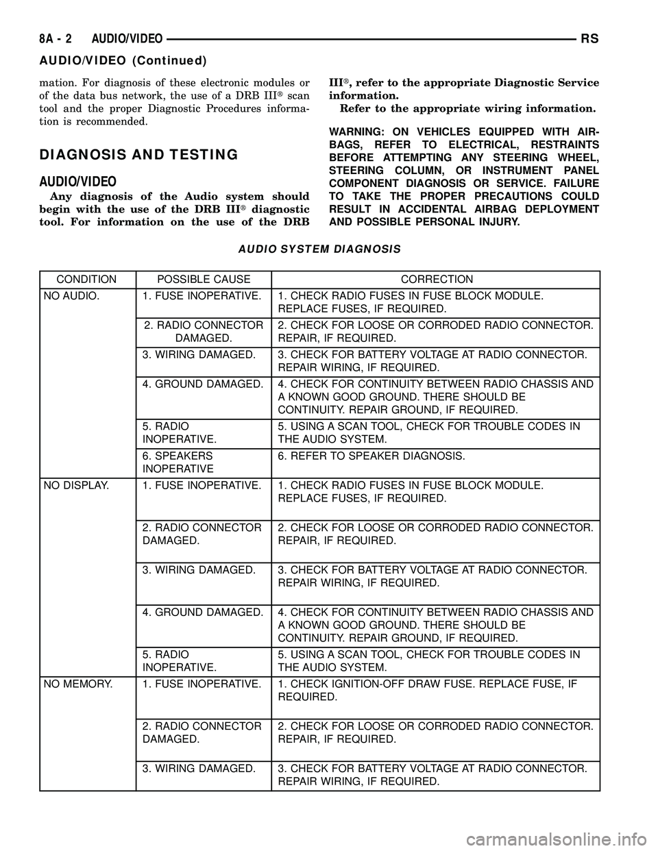
AUDIO SYSTEM DIAGNOSIS
CONDITION POSSIBLE CAUSE CORRECTION
NO AUDIO. 1. FUSE INOPERATIVE. 1. CHECK RADIO FUSES IN FUSE BLOCK MODULE.
REPLACE FUSES, IF REQUIRED.
2. RADIO CONNECTOR
DAMAGED.2. CHECK FOR LOOSE OR CORRODED RADIO CONNECTOR.
REPAIR, IF REQUIRED.
3. WIRING DAMAGED. 3. CHECK FOR BATTERY VOLTAGE AT RADIO CONNECTOR.
REPAIR WIRING, IF REQUIRED.
4. GROUND DAMAGED. 4. CHECK FOR CONTINUITY BETWEEN RADIO CHASSIS AND
A KNOWN GOOD GROUND. THERE SHOULD BE
CONTINUITY. REPAIR GROUND, IF REQUIRED.
5. RADIO
INOPERATIVE.5. USING A SCAN TOOL, CHECK FOR TROUBLE CODES IN
THE AUDIO SYSTEM.
6. SPEAKERS
INOPERATIVE6. REFER TO SPEAKER DIAGNOSIS.
NO DISPLAY. 1. FUSE INOPERATIVE. 1. CHECK RADIO FUSES IN FUSE BLOCK MODULE.
REPLACE FUSES, IF REQUIRED.
2. RADIO CONNECTOR
DAMAGED.2. CHECK FOR LOOSE OR CORRODED RADIO CONNECTOR.
REPAIR, IF REQUIRED.
3. WIRING DAMAGED. 3. CHECK FOR BATTERY VOLTAGE AT RADIO CONNECTOR.
REPAIR WIRING, IF REQUIRED.
4. GROUND DAMAGED. 4. CHECK FOR CONTINUITY BETWEEN RADIO CHASSIS AND
A KNOWN GOOD GROUND. THERE SHOULD BE
CONTINUITY. REPAIR GROUND, IF REQUIRED.
5. RADIO
INOPERATIVE.5. USING A SCAN TOOL, CHECK FOR TROUBLE CODES IN
THE AUDIO SYSTEM.
NO MEMORY. 1. FUSE INOPERATIVE. 1. CHECK IGNITION-OFF DRAW FUSE. REPLACE FUSE, IF
REQUIRED.
2. RADIO CONNECTOR
DAMAGED.2. CHECK FOR LOOSE OR CORRODED RADIO CONNECTOR.
REPAIR, IF REQUIRED.
3. WIRING DAMAGED. 3. CHECK FOR BATTERY VOLTAGE AT RADIO CONNECTOR.
REPAIR WIRING, IF REQUIRED.
8A - 2 AUDIO/VIDEORS
AUDIO/VIDEO (Continued)