hood release CHRYSLER VOYAGER 2005 Service Manual
[x] Cancel search | Manufacturer: CHRYSLER, Model Year: 2005, Model line: VOYAGER, Model: CHRYSLER VOYAGER 2005Pages: 2339, PDF Size: 59.69 MB
Page 151 of 2339
CAUTION: When tightening the primary and sec-
ondary brake tube nuts at master cylinder, be sure
brake tubes do not contact any other components
within the vehicle and that there is slack in the flex-
ible sections of the tubes. This is required due to
the movement between the ABS ICU and the master
cylinder while the vehicle is in motion.
(4) Connect primary and secondary brake tubes to
master cylinder primary and secondary ports (Fig.
50). Brake tubes must be held securely when tight-
ened to control orientation of flex section. Tighten
tube nuts to a torque of 17 N´m (145 in. lbs.).
(5) Install wiring harness connector to brake fluid
level switch mounted in brake fluid reservoir (Fig.
46).
(6) Install battery, clamp and nut.
(7) Install battery shield.
(8) Connect positive battery terminal.
(9) Connect negative battery terminal.
(10) Fill master cylinder with clean, fresh Mopart
Brake Fluid or equivalent.
(11) Road test vehicle to ensure proper operation of
brakes.
PEDALS - ADJUSTABLE
REMOVAL
NOTE: Before proceeding, review all Steering Col-
umn and Airbag Warnings and Cautions. (Refer to
19 - STEERING/COLUMN - WARNING)(Refer to 8 -
ELECTRICAL/RESTRAINTS - WARNING)
(1) Move driver's seat to full rearward position.
(2) Disconnect negative battery cable from battery
post and isolate.
(3) Remove throttle cable from throttle body lever.
(Refer to 14 - FUEL SYSTEM/FUEL INJECTION/
THROTTLE CONTROL CABLE - REMOVAL)
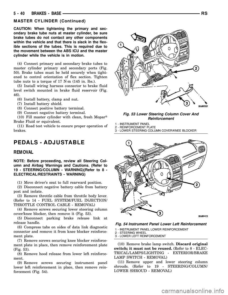
(4) Remove screws securing lower steering column
cover/knee blocker, then remove it (Fig. 53).
(5) Disconnect parking brake release link at
release handle.
(6) Compress tabs on sides of data link diagnostic
connector and remove it from knee blocker reinforce-
ment plate.
(7) Remove screws securing knee blocker reinforce-
ment plate in place, then remove reinforcement plate
(Fig. 53).
(8) Remove hood release from lower left reinforce-
ment.
(9) Remove screws securing instrument panel
lower left reinforcement in place, then remove rein-
forcement (Fig. 54).(10) Remove brake lamp switch.Discard original
switch; it must not be reused.(Refer to 8 - ELEC-
TRICAL/LAMPS/LIGHTING - EXTERIOR/BRAKE
LAMP SWITCH - REMOVAL)
(11) Remove upper and lower steering column
shrouds. (Refer to 19 - STEERING/COLUMN/
LOWER SHROUD - REMOVAL)
Fig. 53 Lower Steering Column Cover And
Reinforcement
1 - INSTRUMENT PANEL
2 - REINFORCEMENT PLATE
3 - LOWER STEERING COLUMN COVER/KNEE BLOCKER
Fig. 54 Instrument Panel Lower Left Reinforcement
1 - INSTRUMENT PANEL LOWER REINFORCEMENT
2 - STEERING WHEEL
3 - LOWER LEFT REINFORCEMENT
5 - 40 BRAKES - BASERS
MASTER CYLINDER (Continued)
Page 154 of 2339
INSTALLATION
(1) Install adjustable pedals assembly under
instrument panel.
(2) Attach throttle cable to accelerator pedal using
cable retainer.
(3) Install two upper mounting bolts attaching
pedals assembly to steering column support bracket
on dash panel.Do not fully tighten at this time.
(4) Install four nuts attaching pedals assembly and
power brake booster to dash panel (Fig. 61).
(5) Tighten four booster mounting nuts and two
upper mounting bolts to 28 N´m (21 ft. lbs.) torque.
(6) Route pedal adjuster cable up and over right
side of pedals assembly and steering column bracket,
then down through hole in steering column bracket
as shown (Fig. 60). Attach end of cable to gear box.
(7) Place adjuster cable through loop on right side
of steering column bracket as shown (Fig. 60).
(8) Install booster input rod onto brake pedal pin
and install a NEW retaining clip.
(9) Connect wiring connector connecting vehicle
wiring harness to pedal wiring harness (Fig. 58).
(10) Connect routing clips retaining vehicle wiring
harness to pedal wiring harness (Fig. 58).
(11) Install brake lamp switch bracket on pedals
assembly. Tighten mounting nuts to 6 N´m (50 in.
lbs.) torque.
(12) Install dash seal silencer shell over steering
column intermediate shaft and fasten in place (Fig.
57).
(13) Install steering column onto lower mounting
studs with nuts started, then install column onto
upper mounting studs and install two upper mount-
ing nuts. Tighten upper, then lower mounting nuts to
12 N´m (105 in. lbs.) torque.
(14) Install column shaft coupling onto intermedi-
ate shaft and install pinch bolt. Make sure rounded
side of intermediate shaft is matched to the curva-
ture of the coupling. Tighten pinch bolt to 28 N´m
(250 in. lbs.) torque.
(15) Remove retainer holding steering wheel in
place on steering column.
(16) Attach shift cable to bracket on column.
(17) Connect shift cable end to shift lever mecha-
nism pin (Fig. 55).
(18) If equipped, connect PRNDL cable to end of
shift lever mechanism pin and column bracket (Fig.
55).(19) Connect column wiring harness connectors (as
equipped) to SKIM, BTSI solenoid, ignition switch,
multi-function switch, and clockspring.
(20) Install lower and upper steering column
shrouds. (Refer to 19 - STEERING/COLUMN/
LOWER SHROUD - INSTALLATION)
CAUTION: Do not reuse the original brake lamp
switch. The switch can only be adjusted once. That
is during initial installation of the switch. If the
switch is not adjusted properly or has been
removed for some service, a new switch must be
installed and adjusted.
(21) Install and adjust NEW brake lamp switch.
(Refer to 8 - ELECTRICAL/LAMPS/LIGHTING -
EXTERIOR/BRAKE LAMP SWITCH - INSTALLA-
TION)
(22) Install instrument panel lower left reinforce-
ment (Fig. 54).
(23) Attach hood release to lower left reinforce-
ment.
(24) Install knee blocker reinforcement plate (Fig.
53).
(25) Connect parking brake release link to release
handle.
(26) Install data link diagnostic connector to
mounting hole in reinforcement plate.
(27) Install lower steering column cover/knee
blocker (Fig. 53).
(28) Install throttle cable onto throttle body lever.
(Refer to 14 - FUEL SYSTEM/FUEL INJECTION/
THROTTLE CONTROL CABLE - INSTALLATION)
NOTE: When reconnecting the battery on a vehicle
that has had the airbag module removed, the fol-
lowing procedure should be used.
(29) Reconnect ground cable to negative post of
battery following special Diagnosis And Testing pro-
cedure. (Refer to 8 - ELECTRICAL/RESTRAINTS -
DIAGNOSIS AND TESTING)
(30) Test operation of adjustable pedals and all
functions that are steering column operated. If appli-
cable, reset radio and clock.
(31) Road test the vehicle to ensure proper opera-
tion of steering and brake systems.
RSBRAKES - BASE5-43
PEDALS - ADJUSTABLE (Continued)
Page 329 of 2339

SPECIAL TOOLS
BATTERY TEMPERATURE
SENSOR
DESCRIPTION
(NGC Vehicles) The PCM incorporates a Battery
Temperature Sensor (BTS) on its circuit board.
OPERATION
The PCM uses the temperature of the battery area
to control the charge system voltage. This tempera-
ture, along with data from monitored line voltage, is
used by the PCM to vary the battery charging rate.
The system voltage is higher at cold temperatures
and is gradually reduced as temperature around the
battery increases.
For vehicles with 1.6L engine, there is no physical
battery temp sensor in place to detect battery temp.
Rather, an algorithm buit in PCM is employed to pre-
dict battery temp using inlet air temp, vehicle speed,
and coolant temp, among other signals. The PCM
maintains the optimal output of the generator by
monitoring battery voltage and controlling it to a
range of 13.5 - 14.7 volts based on battery tempera-
ture. The system target voltage is 13.5 ± 14.7 volts.
However the actual voltage go below this during
heavy electrical loads and generator speeds. Also the
actual voltage can be lower than the target voltage
between the battery and the battery voltage sense
circuit, approximately 0.2 Ð 0.3 volts.
The battery temperature sensor is also used for
OBD II diagnostics. Certain faults and OBD II mon-
itors are either enabled or disabled depending upon
the battery temperature sensor input (example: dis-
able purge and EGR, enable LDP). Most OBD II
monitors are disabled below 20ÉF.
REMOVAL
The battery temperature sensor is not serviced sep-
arately. If replacement is necessary, the PCM must
be replaced.
GENERATOR
DESCRIPTION
The generator is belt-driven by the engine. The
generator produces DC voltage at the B+ terminal. If
the generator is failed, the generator assembly sub-
components (generator and decoupler pulley) must be
inspected for individual failure and replaced accord-
ingly.
OPERATION
As the energized rotor begins to rotate within the
generator, the spinning magnetic field induces a cur-
rent into the windings of the stator coil. Once the
generator begins producing sufficient current, it also
provides the current needed to energize the rotor.
The Y type stator winding connections deliver the
induced AC current to 3 positive and 3 negative
diodes for rectification. From the diodes, rectified DC
current is delivered to the vehicles electrical system
through the generator, battery, and ground terminals.
Excessive or abnormal noise emitting from the gen-
erator may be caused by:
²Worn, loose or defective bearings
²Loose or defective drive pulley (2.4L) or decou-
pler (3.3/3.8L)
²Incorrect, worn, damaged or misadjusted drive
belt
²Loose mounting bolts
²Misaligned drive pulley
²Defective stator or diode
²Damaged internal fins
REMOVAL
REMOVAL - 2.4L
(1) Release hood latch and open hood.
(2) Disconnect battery negative cable.
(3) Disconnect the Inlet Air Temperature sensor.
(4) Remove the Air Box, refer to the Engine/Air
Cleaner for more information.
(5) Remove the EVAP Purge solenoid from its
bracket and reposition.
(6) Disconnect the push-in field wire connector
from back of generator.
(7) Remove nut holding B+ wire terminal to back
of generator.
(8) Separate B+ terminal from generator.
GENERATOR DECOUPLER 8433
8F - 24 CHARGINGRS
CHARGING (Continued)
Page 332 of 2339
REMOVAL - 3.3/3.8L
(1) Release hood latch and open hood.
(2) Disconnect battery negative cable.
(3) Disconnect the push-in field wire connector
from back of generator.
(4) Remove nut holding B+ wire terminal to back
of generator.
(5) Separate B+ terminal from generator.
(6) Raise vehicle and support.
(7) Remove the right front lower splash shield.
(8) Remove accessory drive belt, refer to the Cool-
ing System section for proper procedures.
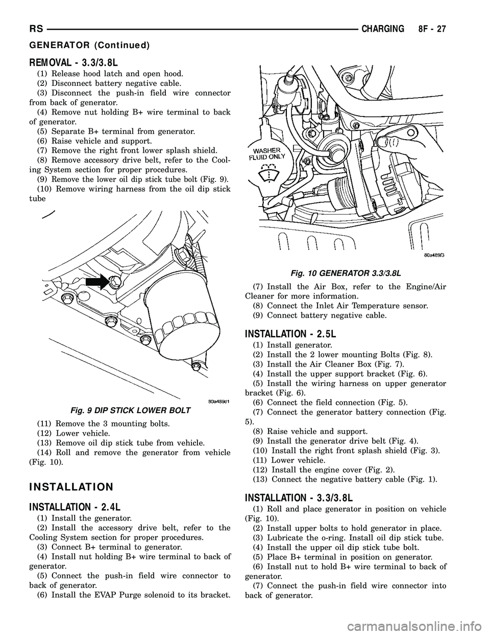
(9)
Remove the lower oil dip stick tube bolt (Fig. 9).
(10) Remove wiring harness from the oil dip stick
tube
(11) Remove the 3 mounting bolts.
(12) Lower vehicle.
(13) Remove oil dip stick tube from vehicle.
(14) Roll and remove the generator from vehicle
(Fig. 10).
INSTALLATION
INSTALLATION - 2.4L
(1) Install the generator.
(2) Install the accessory drive belt, refer to the
Cooling System section for proper procedures.
(3) Connect B+ terminal to generator.
(4) Install nut holding B+ wire terminal to back of
generator.
(5) Connect the push-in field wire connector to
back of generator.
(6) Install the EVAP Purge solenoid to its bracket.(7) Install the Air Box, refer to the Engine/Air
Cleaner for more information.
(8) Connect the Inlet Air Temperature sensor.
(9) Connect battery negative cable.
INSTALLATION - 2.5L
(1) Install generator.
(2) Install the 2 lower mounting Bolts (Fig. 8).
(3) Install the Air Cleaner Box (Fig. 7).
(4) Install the upper support bracket (Fig. 6).
(5) Install the wiring harness on upper generator
bracket (Fig. 6).
(6) Connect the field connection (Fig. 5).
(7) Connect the generator battery connection (Fig.
5).
(8) Raise vehicle and support.
(9) Install the generator drive belt (Fig. 4).
(10) Install the right front splash shield (Fig. 3).
(11) Lower vehicle.
(12) Install the engine cover (Fig. 2).
(13) Connect the negative battery cable (Fig. 1).
INSTALLATION - 3.3/3.8L
(1) Roll and place generator in position on vehicle
(Fig. 10).
(2) Install upper bolts to hold generator in place.
(3) Lubricate the o-ring. Install oil dip stick tube.
(4) Install the upper oil dip stick tube bolt.
(5) Place B+ terminal in position on generator.
(6) Install nut to hold B+ wire terminal to back of
generator.
(7) Connect the push-in field wire connector into
back of generator.
Fig. 9 DIP STICK LOWER BOLT
Fig. 10 GENERATOR 3.3/3.8L
RSCHARGING8F-27
GENERATOR (Continued)
Page 334 of 2339
REMOVAL
(1) Release hood latch and open hood.
(2) Disconnect battery negative cable.
(3) Raise vehicle and support.
(4) Remove the right front lower splash shield.
(5) Remove accessory drive belt, refer to the Cool-
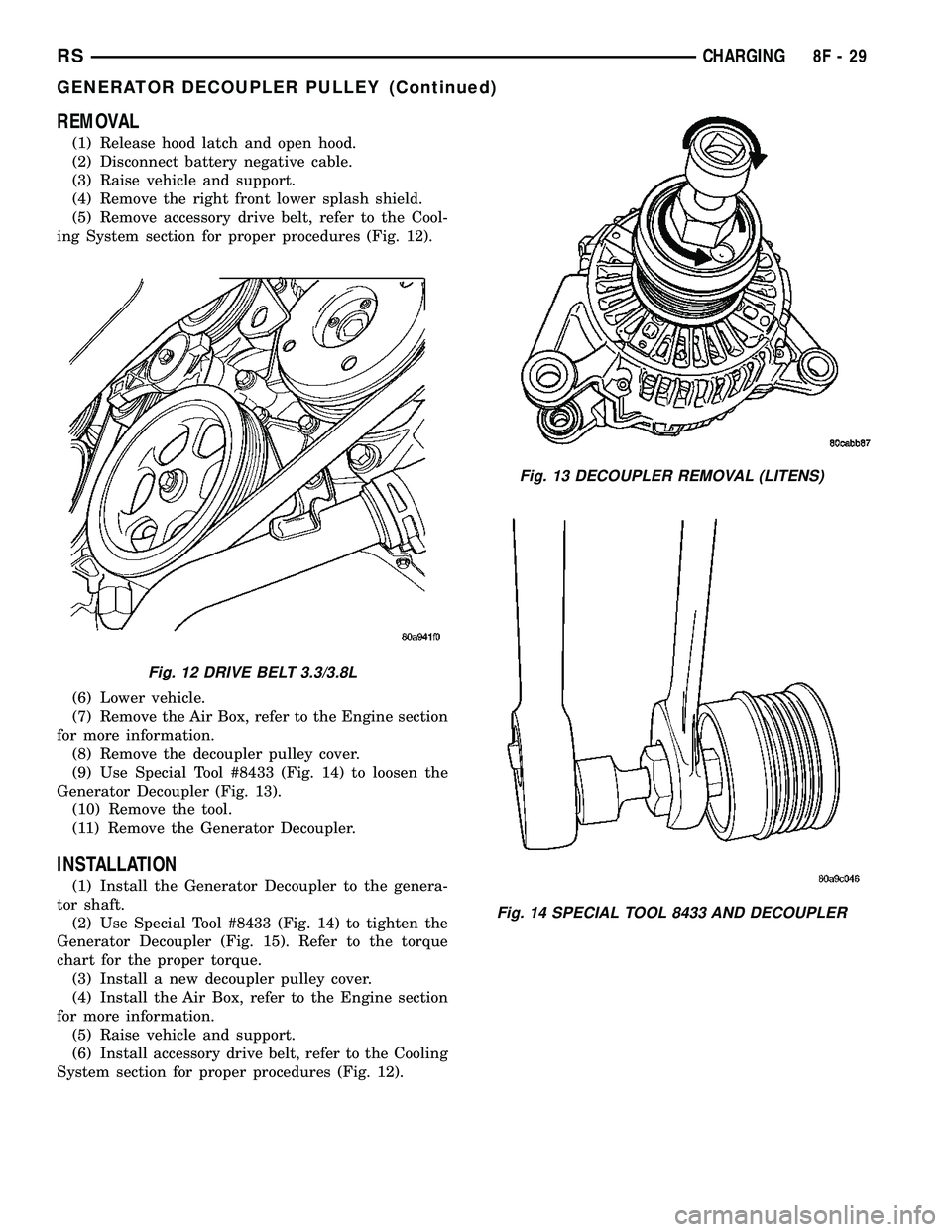
ing System section for proper procedures (Fig. 12).
(6) Lower vehicle.
(7) Remove the Air Box, refer to the Engine section
for more information.
(8) Remove the decoupler pulley cover.
(9) Use Special Tool #8433 (Fig. 14) to loosen the
Generator Decoupler (Fig. 13).
(10) Remove the tool.
(11) Remove the Generator Decoupler.
INSTALLATION
(1) Install the Generator Decoupler to the genera-
tor shaft.
(2) Use Special Tool #8433 (Fig. 14) to tighten the
Generator Decoupler (Fig. 15). Refer to the torque
chart for the proper torque.
(3) Install a new decoupler pulley cover.
(4) Install the Air Box, refer to the Engine section
for more information.
(5) Raise vehicle and support.
(6) Install accessory drive belt, refer to the Cooling
System section for proper procedures (Fig. 12).
Fig. 12 DRIVE BELT 3.3/3.8L
Fig. 13 DECOUPLER REMOVAL (LITENS)
Fig. 14 SPECIAL TOOL 8433 AND DECOUPLER
RSCHARGING8F-29
GENERATOR DECOUPLER PULLEY (Continued)
Page 342 of 2339
STARTER
MANUFACTURER NIPPONDENSO
Engine Application 2.4L /3.3/3.8L
Power rating 1.2 Kw
Voltage 12 VOLTS
No. of Fields 4
No. of Poles 4
Brushes 4
Drive Conventional Gear Train
Free running Test
Voltage 11
Amperage Draw 73 Amp
Minimum Speed 3401 RPM
SolenoidClosing Voltage 7.5 Volts
Cranking Amperage Draw
test150 - 200 Amps.
Engine should be up to operating temperature.
Extremely heavy oil or tight engine will increase
starter amperage draw.
STARTER MOTOR
REMOVAL
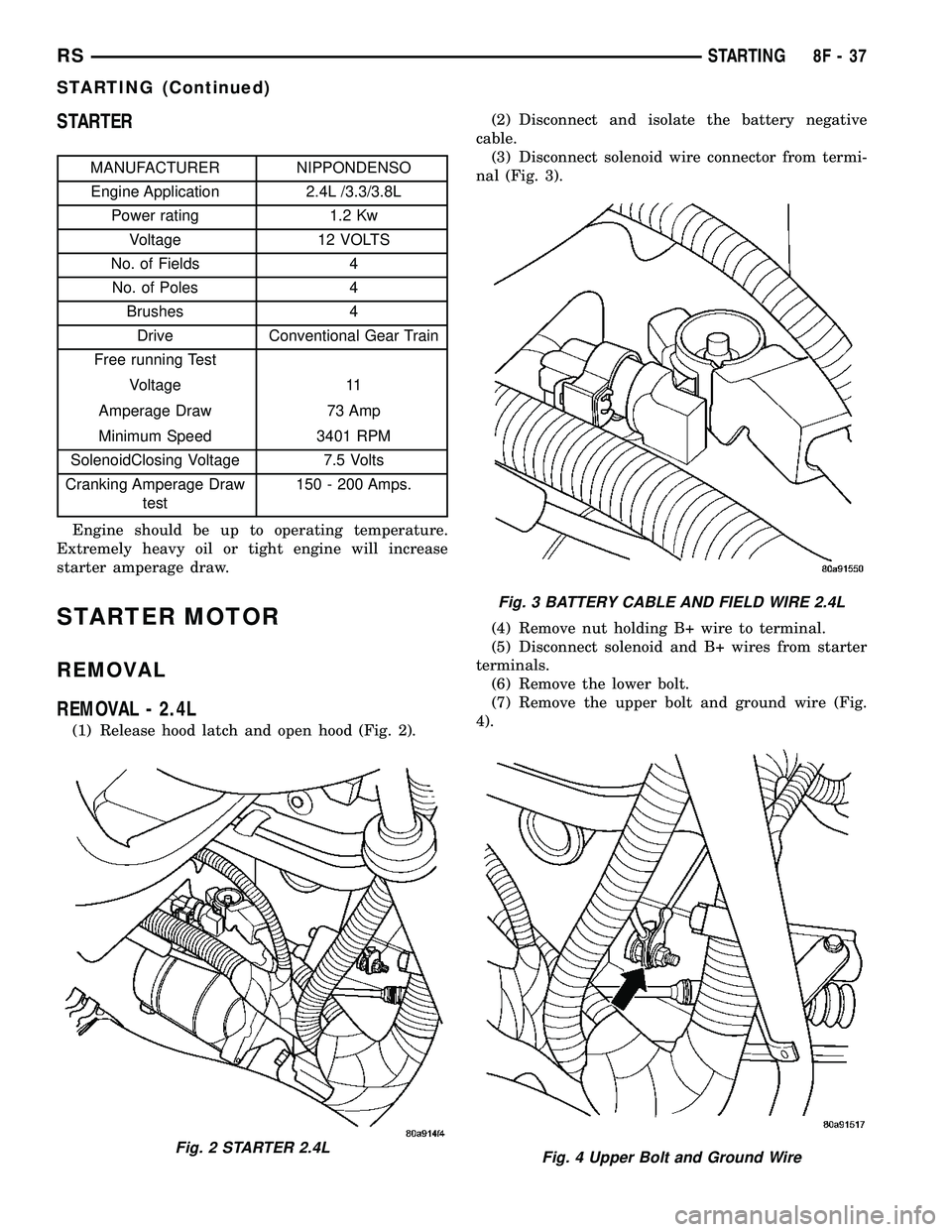
REMOVAL - 2.4L
(1) Release hood latch and open hood (Fig. 2).(2) Disconnect and isolate the battery negative
cable.
(3) Disconnect solenoid wire connector from termi-
nal (Fig. 3).
(4) Remove nut holding B+ wire to terminal.
(5) Disconnect solenoid and B+ wires from starter
terminals.
(6) Remove the lower bolt.
(7) Remove the upper bolt and ground wire (Fig.
4).
Fig. 2 STARTER 2.4L
Fig. 3 BATTERY CABLE AND FIELD WIRE 2.4L
Fig. 4 Upper Bolt and Ground Wire
RSSTARTING8F-37
STARTING (Continued)
Page 343 of 2339
(8) Remove starter.
REMOVAL - 3.3/3.8L
(1) Release hood latch and open hood.
(2) Disconnect and isolate the battery negative
cable.
(3) Hoist and support vehicle on safety stands.
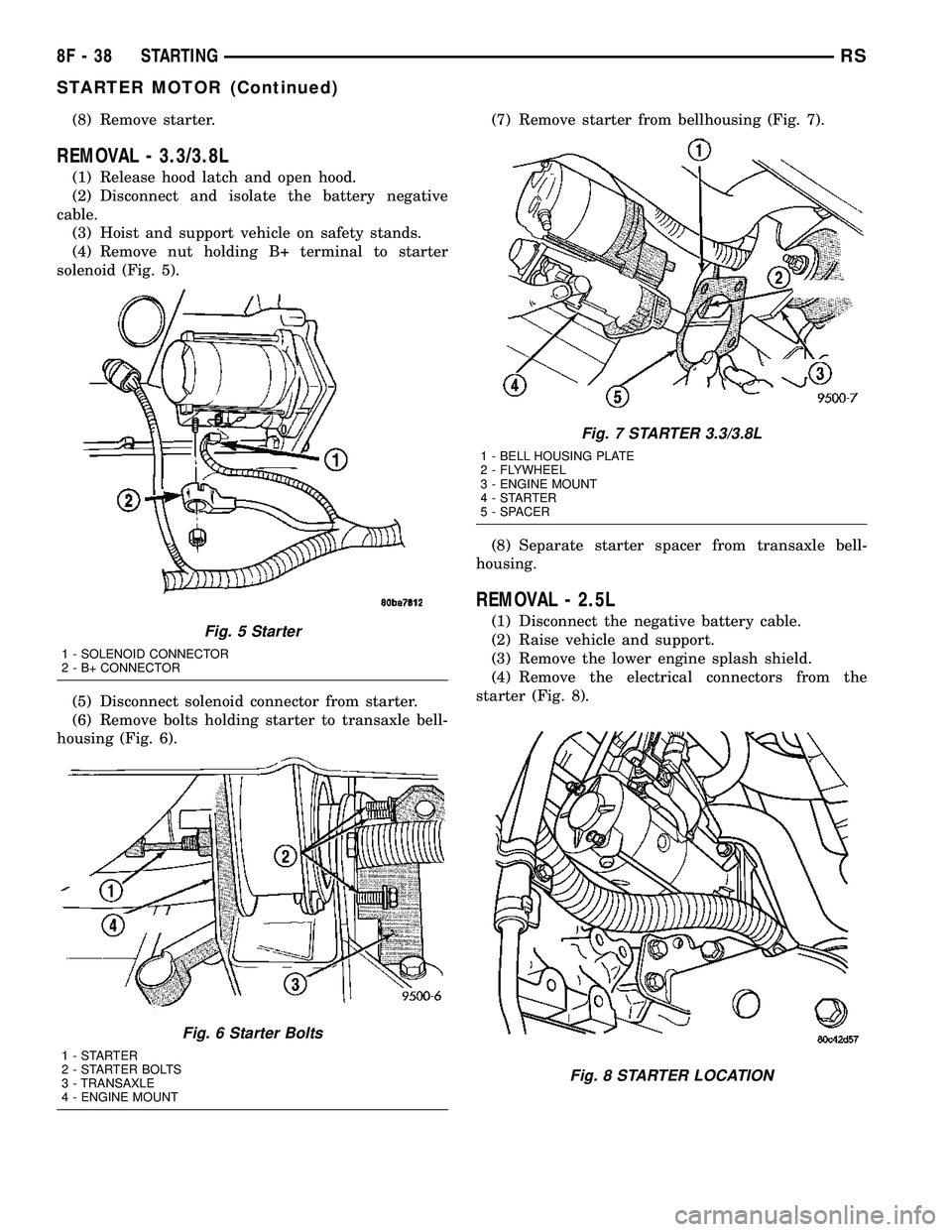
(4) Remove nut holding B+ terminal to starter
solenoid (Fig. 5).
(5) Disconnect solenoid connector from starter.
(6) Remove bolts holding starter to transaxle bell-
housing (Fig. 6).(7) Remove starter from bellhousing (Fig. 7).
(8) Separate starter spacer from transaxle bell-
housing.
REMOVAL - 2.5L
(1) Disconnect the negative battery cable.
(2) Raise vehicle and support.
(3) Remove the lower engine splash shield.
(4) Remove the electrical connectors from the
starter (Fig. 8).Fig. 5 Starter
1 - SOLENOID CONNECTOR
2 - B+ CONNECTOR
Fig. 6 Starter Bolts
1-STARTER
2 - STARTER BOLTS
3 - TRANSAXLE
4 - ENGINE MOUNT
Fig. 7 STARTER 3.3/3.8L
1 - BELL HOUSING PLATE
2 - FLYWHEEL
3 - ENGINE MOUNT
4-STARTER
5 - SPACER
Fig. 8 STARTER LOCATION
8F - 38 STARTINGRS
STARTER MOTOR (Continued)
Page 498 of 2339
Service replacement clocksprings are shipped pre-
centered and with a molded plastic shield that snaps
onto the rotor over the release button. The release
button secures the centered clockspring rotor to the
clockspring case and the shield prevents the release
button from being inadvertently depressed during
shipment and handling, but the shield must be
removed from the clockspring after it is installed on
the steering column (Refer to 8 - ELECTRICAL/RE-
STRAINTS/CLOCKSPRING - STANDARD PROCE-
DURE).
The clockspring cannot be repaired. If the clock-
spring is faulty, damaged, or if the driver airbag has
been deployed, the clockspring must be replaced.
OPERATION
The clockspring is a mechanical electrical circuit
component that is used to provide continuous electri-
cal continuity between the fixed instrument panel
wire harness and the electrical components mounted
on or in the rotating steering wheel. The rotating
electrical components include the driver airbag, the
horn switch, the speed control switches, and the
remote radio switches, if the vehicle is so equipped.
The clockspring case is positioned and secured to the
upper steering column housing near the top of the
steering column. The connector receptacles on the
tail of the clockspring case connect the clockspring to
the vehicle electrical system through two connectors
from the instrument panel wire harness.
The clockspring rotor is movable and is keyed by
the tower formation that is molded onto the upper
surface of the rotor hub to an opening that is cast
into the steering wheel armature. Rubber bumper
blocks on either side of the clockspring tower forma-
tion eliminate contact noise between the clockspring
tower and the steering wheel. The lobe of the turn
signal cancel cam on the lower surface of the clock-
spring rotor hub contacts a turn signal cancel actua-
tor of the multi-function switch to provide automatic
turn signal cancellation. The yellow or black-sleeved
pigtail wires on the upper surface of the clockspring
rotor connect the clockspring to the driver airbag,
while a steering wheel wire harness connects the
connector receptacle on the upper surface of the
clockspring rotor to the horn switch and, if the vehi-
cle is so equipped, to the optional speed control
switches and remote radio switches on the steering
wheel.
The clockspring tape has travel limits and can be
damaged by being wound too tightly during full stop-
to-stop steering wheel rotation. To prevent this from
occurring, the clockspring is centered when it is
installed on the steering column. Centering the clock-
spring indexes the clockspring tape to the movable
steering components so that the tape can operatewithin its designed travel limits. However, if the
clockspring is removed from the steering column or if
the steering shaft is disconnected from the steering
gear, the clockspring spool can change position rela-
tive to the movable steering components and must be
re-centered following completion of the service or the
tape may be damaged (Refer to 8 - ELECTRICAL/
RESTRAINTS/CLOCKSPRING - STANDARD PRO-
CEDURE).
Service replacement clocksprings are shipped pre-
centered and with a plastic shield installed over the
clockspring release button. This shield should not be
removed and the release button should not be
depressed until the clockspring has been installed on
the steering column. If the release button is
depressed before the clockspring is installed on a
steering column, the clockspring centering procedure
must be performed (Refer to 8 - ELECTRICAL/RE-
STRAINTS/CLOCKSPRING - STANDARD PROCE-
DURE).
STANDARD PROCEDURE - CLOCKSPRING
CENTERING
If the rotating tape (wire coil) in the clockspring is
not positioned properly with the steering wheel and
the front wheels, the clockspring may fail. The fol-
lowing procedure MUST BE USED to center the
clockspring if it is not known to be properly posi-
tioned, or if the front wheels were moved from the
straight ahead position.
(1) Position steering wheel and front wheels
straight ahead.
(2) Release hood latch and open hood.
(3) Disconnect and isolate the battery negative
cable.
(4) Wait two minutes for the system reserve capac-
itor to discharge before beginning any airbag compo-
nent service.
(5) Remove driver airbag from steering wheel
(Refer to 8 - ELECTRICAL/RESTRAINTS/DRIVER
AIRBAG - REMOVAL).
(6) Disconnect wire connectors from back of driver
airbag.
(7) Disconnect the 2±way connector from remote
radio control harness (if equipped).
(8) Disconnect the 4±way harness connector from
the speed control (if equipped)/horn harness to the
clockspring.
(9) Remove steering wheel (Refer to 19 - STEER-
ING/COLUMN/STEERING WHEEL - REMOVAL).
(10) Rotate the clockspring rotor clockwise until
the rotor stops. Do not apply excessive force.
(11) From the end of travel, rotate the rotor two
turns counterclockwise until the wires end up at the
top.
RSRESTRAINTS8O-11
CLOCKSPRING (Continued)
Page 499 of 2339
(12) Install the steering wheel (Refer to 19 -
STEERING/COLUMN/STEERING WHEEL -
INSTALLATION).
(13) Connect the 4±way harness connector to the
speed control/horn harness to the clockspring.
(14) Connect the 2±way connector to the remote
radio control harness.
(15) Install the driver airbag (Refer to 8 - ELEC-
TRICAL/RESTRAINTS/DRIVER AIRBAG - INSTAL-
LATION). Torque the two screws to 10 N´m (90 in.
lbs.).
WARNING: Do not connect the battery negative
cable (Refer to 8 - ELECTRICAL/RESTRAINTS -
DIAGNOSIS AND TESTING). Personal injury or
death may result if the system test is not performed
properly.
REMOVAL
(1) Position steering wheel and front wheels
straight ahead.
(2) Release hood latch and open hood.
(3) Disconnect and isolate the battery negative
cable.
(4)
WARNING: Wait two minutes for the airbag system
reserve capacitor to discharge before beginning
any airbag system or component service. Failure to
do so may result in accidental airbag deployment,
personal injury or death.
(5) Remove driver airbag from steering wheel
(Refer to 8 - ELECTRICAL/RESTRAINTS/DRIVER
AIRBAG - REMOVAL).
(6) Disconnect wire connectors from back of driver
airbag.
(7) Disconnect the 2±way connector from remote
radio control harness.
(8) Disconnect the 4±way harness connector from
the speed control/horn harness to the clockspring.
(9) Remove steering wheel (Refer to 19 - STEER-
ING/COLUMN/STEERING WHEEL - REMOVAL).
(10) Remove steering column shrouds and discon-
nect traction control wire connector (if equipped)
(Refer to 19 - STEERING/COLUMN/LOWER
SHROUD - REMOVAL).
(11) Disconnect 4-way and 6-way connectors
between the clockspring and the instrument panel
wiring harness.
(12) Remove clockspring from column assembly by
removing the two retaining screws that attach the
clock spring to the column.
INSTALLATION
(1) Install the clockspring on the column.
(2) Connect the 4-way and 6-way connectors
between the clockspring and the instrument panel
wiring harness.
(3) Install the steering column shrouds and con-
nect traction control wire connector (if equipped)
(Refer to 19 - STEERING/COLUMN/LOWER
SHROUD - INSTALLATION).
(4) Install the steering wheel (Refer to 19 -
STEERING/COLUMN/STEERING WHEEL -
INSTALLATION).
(5) Connect the 4±way harness connector to the
speed control/horn harness to the clockspring.
(6) Connect the 2±way connector to the remote
radio control harness (if equipped).
(7) Install the driver airbag (Refer to 8 - ELEC-
TRICAL/RESTRAINTS/DRIVER AIRBAG - INSTAL-
LATION). Torque the two screws to 10 N´m (90 in.
lbs.).
WARNING: Do not connect the battery negative
cable (Refer to 8 - ELECTRICAL/RESTRAINTS -
DIAGNOSIS AND TESTING - AIRBAG SYSTEM). Per-
sonal injury or death may result if the system test
is not performed first.
CURTAIN AIRBAG
DESCRIPTION
Curtain Airbags (Fig. 11) are available when it is
also equipped with dual front airbags. These airbags
are passive and inflatable, Supplemental Restraint
System (SRS) components, and vehicles with this
equipment can be readily identified by a molded
identification trim button with the ªSRS - AIRBAGº
logo (Fig. 12) located on the B-pillar and C-pillar
upper trim panels. This system is designed to reduce
injuries to the vehicle occupants in the event of a
side impact collision.
Curtain airbags have two individually controlled
curtain airbag units. These airbag units are con-
cealed and mounted above the headliner where they
are each secured to one of the roof side rails (Fig.
13). Each airbag cushion is contained within a fabric
wrap that extends along the roof rail from the A-pil-
lar at the front of the vehicle to just behind the
D-pillar at the rear of the vehicle. One tether extends
down the A-pillar from the front of the airbag cush-
ion, and a second tether extends to the roof rail at
the D-pillar. The end of the A-pillar tether is secured
to a slot in the sheet metal with a metal hook
retained by a bolt. The D-pillar tether is attached to
the d-pillar.
8O - 12 RESTRAINTSRS
CLOCKSPRING (Continued)
Page 500 of 2339
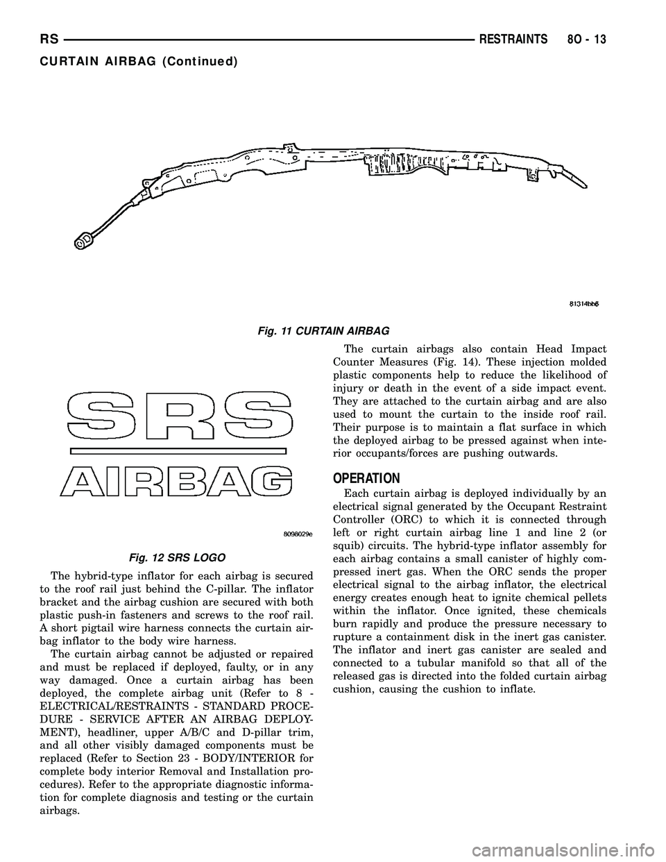
The hybrid-type inflator for each airbag is secured
to the roof rail just behind the C-pillar. The inflator
bracket and the airbag cushion are secured with both
plastic push-in fasteners and screws to the roof rail.
A short pigtail wire harness connects the curtain air-
bag inflator to the body wire harness.
The curtain airbag cannot be adjusted or repaired
and must be replaced if deployed, faulty, or in any
way damaged. Once a curtain airbag has been
deployed, the complete airbag unit (Refer to 8 -
ELECTRICAL/RESTRAINTS - STANDARD PROCE-
DURE - SERVICE AFTER AN AIRBAG DEPLOY-
MENT), headliner, upper A/B/C and D-pillar trim,
and all other visibly damaged components must be
replaced (Refer to Section 23 - BODY/INTERIOR for
complete body interior Removal and Installation pro-
cedures). Refer to the appropriate diagnostic informa-
tion for complete diagnosis and testing or the curtain
airbags.The curtain airbags also contain Head Impact
Counter Measures (Fig. 14). These injection molded
plastic components help to reduce the likelihood of
injury or death in the event of a side impact event.
They are attached to the curtain airbag and are also
used to mount the curtain to the inside roof rail.
Their purpose is to maintain a flat surface in which
the deployed airbag to be pressed against when inte-
rior occupants/forces are pushing outwards.
OPERATION
Each curtain airbag is deployed individually by an
electrical signal generated by the Occupant Restraint
Controller (ORC) to which it is connected through
left or right curtain airbag line 1 and line 2 (or
squib) circuits. The hybrid-type inflator assembly for
each airbag contains a small canister of highly com-
pressed inert gas. When the ORC sends the proper
electrical signal to the airbag inflator, the electrical
energy creates enough heat to ignite chemical pellets
within the inflator. Once ignited, these chemicals
burn rapidly and produce the pressure necessary to
rupture a containment disk in the inert gas canister.
The inflator and inert gas canister are sealed and
connected to a tubular manifold so that all of the
released gas is directed into the folded curtain airbag
cushion, causing the cushion to inflate.
Fig. 11 CURTAIN AIRBAG
Fig. 12 SRS LOGO
RSRESTRAINTS8O-13
CURTAIN AIRBAG (Continued)