CHRYSLER VOYAGER 2005 Service Manual
Manufacturer: CHRYSLER, Model Year: 2005, Model line: VOYAGER, Model: CHRYSLER VOYAGER 2005Pages: 2339, PDF Size: 59.69 MB
Page 1531 of 2339
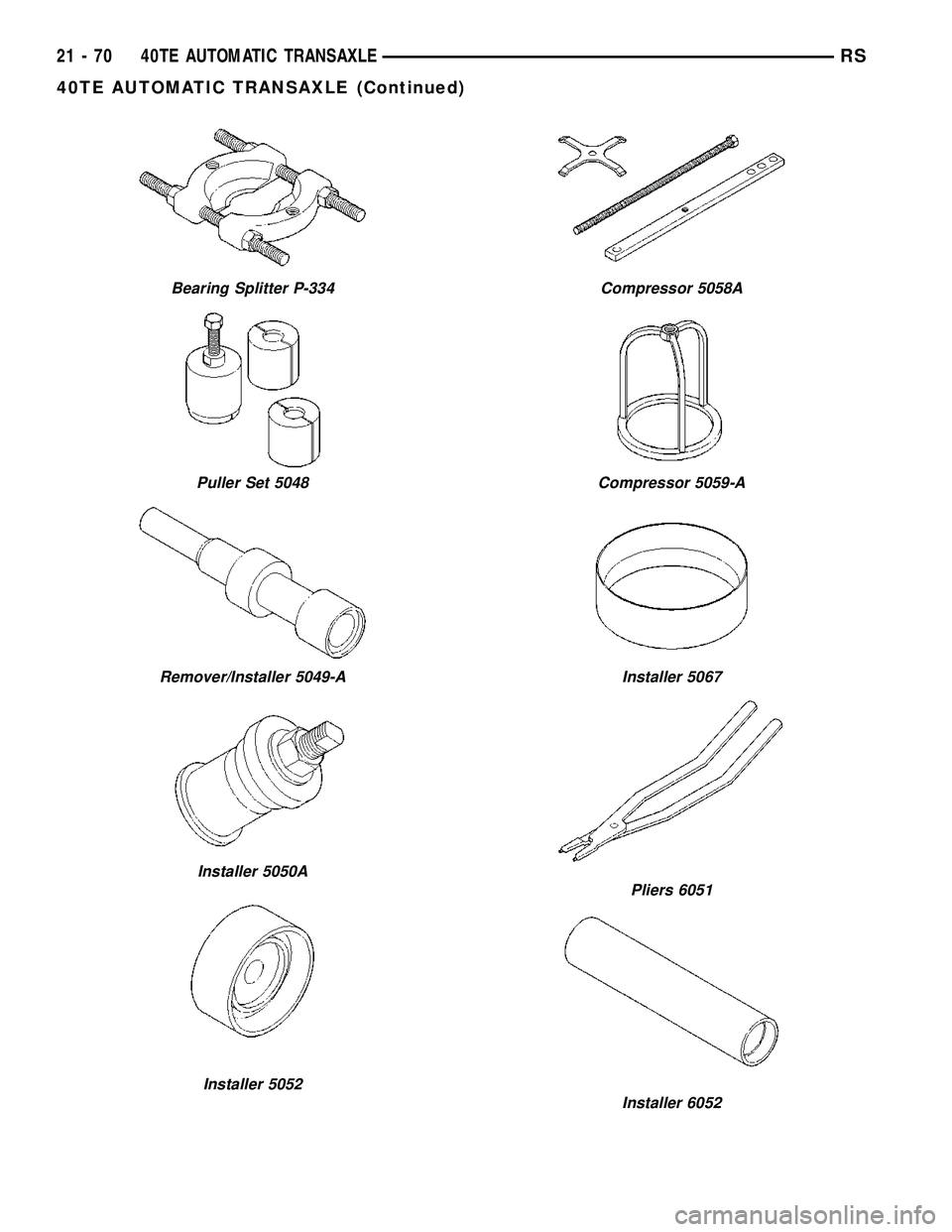
Bearing Splitter P-334
Puller Set 5048
Remover/Installer 5049-A
Installer 5050A
Installer 5052
Compressor 5058A
Compressor 5059-A
Installer 5067
Pliers 6051
Installer 6052
21 - 70 40TE AUTOMATIC TRANSAXLERS
40TE AUTOMATIC TRANSAXLE (Continued)
Page 1532 of 2339
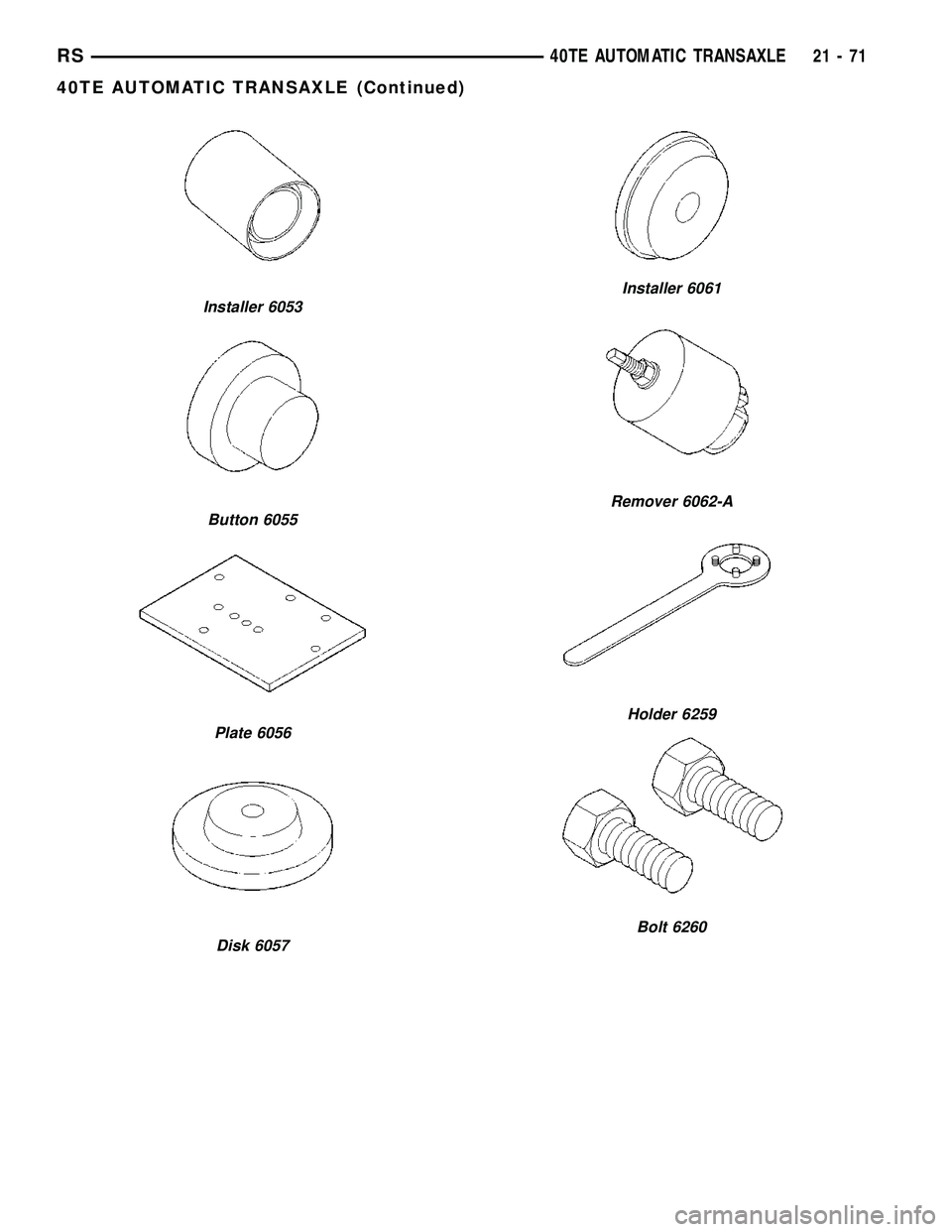
Installer 6053
Button 6055
Plate 6056
Disk 6057
Installer 6061
Remover 6062-A
Holder 6259
Bolt 6260
RS40TE AUTOMATIC TRANSAXLE21-71
40TE AUTOMATIC TRANSAXLE (Continued)
Page 1533 of 2339
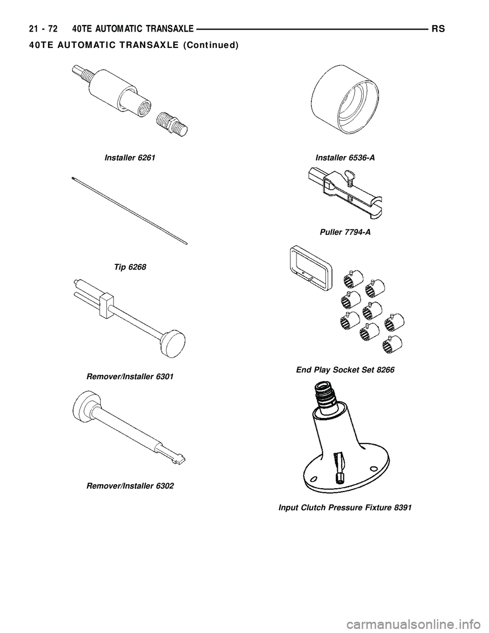
Installer 6261
Tip 6268
Remover/Installer 6301
Remover/Installer 6302
Installer 6536-A
Puller 7794-A
End Play Socket Set 8266
Input Clutch Pressure Fixture 8391
21 - 72 40TE AUTOMATIC TRANSAXLERS
40TE AUTOMATIC TRANSAXLE (Continued)
Page 1534 of 2339

ACCUMULATOR
DESCRIPTION
The 4XTE underdrive, overdrive, low/reverse, and
2/4 clutch hydraulic circuits each contain an accumu-
lator. An accumulator typically consists of a piston,
return spring(s), and a cover or plug. The overdrive
and underdrive accumulators are located within the
transaxle case, and are retained by the valve body
(Fig. 164).
The low reverse accumulator (Fig. 165) is also
located within the transaxle case, but the assembly is
retained by a cover and a snap-ring.
The 2/4 accumulator is located in the valve body. It
is retained by a cover and retaining screws (Fig.
166).
OPERATION
The function of an accumulator is to cushion the
application of a frictional clutch element. When pres-
surized fluid is applied to a clutch circuit, the appli-
cation force is dampened by fluid collecting in therespective accumulator chamber against the piston
and spring(s). The intended result is a smooth, firm
clutch application.
Fig. 164 Underdrive and Overdrive Accumulators
1 - OVERDRIVE PISTON AND SPRING
2 - UNDERDRIVE PISTON AND SPRING
Fig. 165 Low/Reverse Accumulator
1 - PISTON
2 - RETURN SPRINGS
Fig. 166 2/4 Accumulator Assembly
1 - VALVE BODY
2 - RETAINER PLATE
3 - DETENT SPRING
4 - RETURN SPRINGS
5 - PISTON
RS40TE AUTOMATIC TRANSAXLE21-73
Page 1535 of 2339
DRIVING CLUTCHES
DESCRIPTION
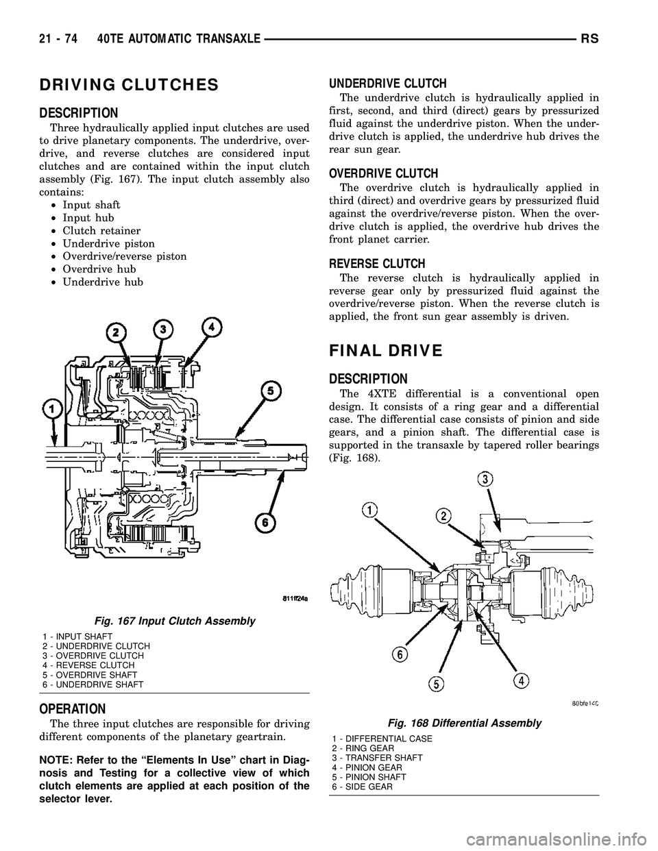
Three hydraulically applied input clutches are used
to drive planetary components. The underdrive, over-
drive, and reverse clutches are considered input
clutches and are contained within the input clutch
assembly (Fig. 167). The input clutch assembly also
contains:
²Input shaft
²Input hub
²Clutch retainer
²Underdrive piston
²Overdrive/reverse piston
²Overdrive hub
²Underdrive hub
OPERATION
The three input clutches are responsible for driving
different components of the planetary geartrain.
NOTE: Refer to the ªElements In Useº chart in Diag-
nosis and Testing for a collective view of which
clutch elements are applied at each position of the
selector lever.
UNDERDRIVE CLUTCH
The underdrive clutch is hydraulically applied in
first, second, and third (direct) gears by pressurized
fluid against the underdrive piston. When the under-
drive clutch is applied, the underdrive hub drives the
rear sun gear.
OVERDRIVE CLUTCH
The overdrive clutch is hydraulically applied in
third (direct) and overdrive gears by pressurized fluid
against the overdrive/reverse piston. When the over-
drive clutch is applied, the overdrive hub drives the
front planet carrier.
REVERSE CLUTCH
The reverse clutch is hydraulically applied in
reverse gear only by pressurized fluid against the
overdrive/reverse piston. When the reverse clutch is
applied, the front sun gear assembly is driven.
FINAL DRIVE
DESCRIPTION
The 4XTE differential is a conventional open
design. It consists of a ring gear and a differential
case. The differential case consists of pinion and side
gears, and a pinion shaft. The differential case is
supported in the transaxle by tapered roller bearings
(Fig. 168).
Fig. 167 Input Clutch Assembly
1 - INPUT SHAFT
2 - UNDERDRIVE CLUTCH
3 - OVERDRIVE CLUTCH
4 - REVERSE CLUTCH
5 - OVERDRIVE SHAFT
6 - UNDERDRIVE SHAFT
Fig. 168 Differential Assembly
1 - DIFFERENTIAL CASE
2 - RING GEAR
3 - TRANSFER SHAFT
4 - PINION GEAR
5 - PINION SHAFT
6 - SIDE GEAR
21 - 74 40TE AUTOMATIC TRANSAXLERS
Page 1536 of 2339

OPERATION
The differential assembly is driven by the transfer
shaft by way of the differential ring gear. The ring
gear drives the differential case, and the case drives
the driveshafts through the differential gears. The
differential pinion and side gears are supported in
the case by thrust washers and a pinion shaft. Dif-
ferential pinion and side gears make it possible for
front tires to rotate at different speeds while corner-
ing.
DISASSEMBLY
NOTE: The differential is serviced as an assembly.
The only parts that are serviceable within the differ-
ential are the differential bearing cups and cones. If
any other part fails within the differential, you must
replace the differential assembly along with the
transfer shaft.
The transfer shaft should be removed for differen-
tial repair and bearing turning torque checking.
(1) Remove the differential cover and bolts (Fig.
169) (Fig. 170).(2) Remove the differential bearing retainer and
bolts (Fig. 171) (Fig. 172).
Fig. 169 Differential Cover Bolts
1 - DIFFERENTIAL COVER BOLTS
2 - DIFFERENTIAL COVER
Fig. 170 Remove Differential Cover
1 - DIFFERENTIAL ASSEMBLY
2 - DIFFERENTIAL COVER
Fig. 171 Differential Retainer Bolts
1 - DIFFERENTIAL RETAINER BOLTS
RS40TE AUTOMATIC TRANSAXLE21-75
FINAL DRIVE (Continued)
Page 1537 of 2339
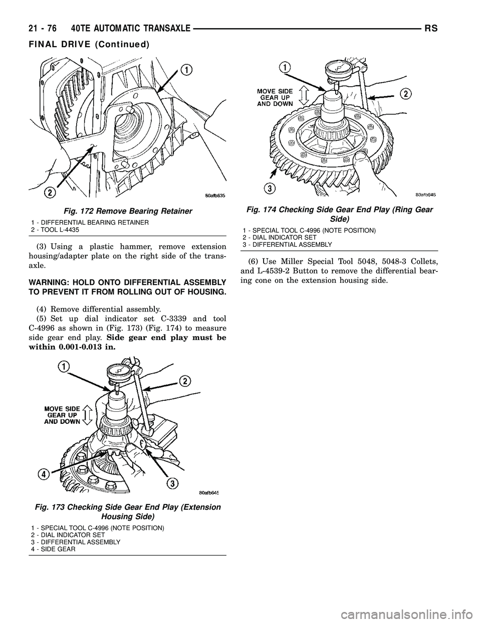
(3) Using a plastic hammer, remove extension
housing/adapter plate on the right side of the trans-
axle.
WARNING: HOLD ONTO DIFFERENTIAL ASSEMBLY
TO PREVENT IT FROM ROLLING OUT OF HOUSING.
(4) Remove differential assembly.
(5) Set up dial indicator set C-3339 and tool
C-4996 as shown in (Fig. 173) (Fig. 174) to measure
side gear end play.Side gear end play must be
within 0.001-0.013 in.(6) Use Miller Special Tool 5048, 5048-3 Collets,
and L-4539-2 Button to remove the differential bear-
ing cone on the extension housing side.
Fig. 172 Remove Bearing Retainer
1 - DIFFERENTIAL BEARING RETAINER
2 - TOOL L-4435
Fig. 173 Checking Side Gear End Play (Extension
Housing Side)
1 - SPECIAL TOOL C-4996 (NOTE POSITION)
2 - DIAL INDICATOR SET
3 - DIFFERENTIAL ASSEMBLY
4 - SIDE GEAR
Fig. 174 Checking Side Gear End Play (Ring Gear
Side)
1 - SPECIAL TOOL C-4996 (NOTE POSITION)
2 - DIAL INDICATOR SET
3 - DIFFERENTIAL ASSEMBLY
21 - 76 40TE AUTOMATIC TRANSAXLERS
FINAL DRIVE (Continued)
Page 1538 of 2339
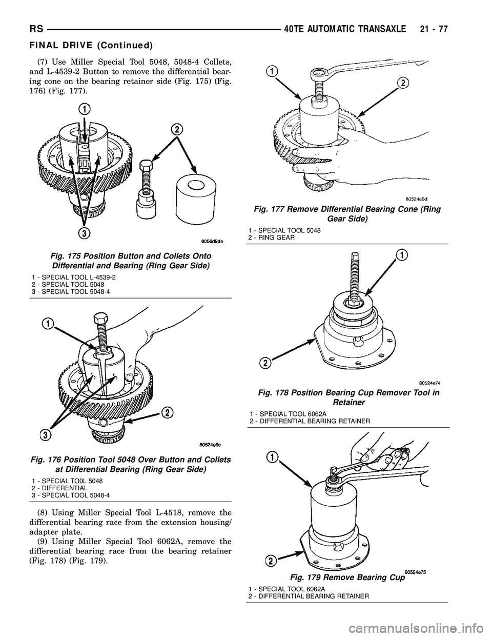
(7) Use Miller Special Tool 5048, 5048-4 Collets,
and L-4539-2 Button to remove the differential bear-
ing cone on the bearing retainer side (Fig. 175) (Fig.
176) (Fig. 177).
(8) Using Miller Special Tool L-4518, remove the
differential bearing race from the extension housing/
adapter plate.
(9) Using Miller Special Tool 6062A, remove the
differential bearing race from the bearing retainer
(Fig. 178) (Fig. 179).
Fig. 175 Position Button and Collets Onto
Differential and Bearing (Ring Gear Side)
1 - SPECIAL TOOL L-4539-2
2 - SPECIAL TOOL 5048
3 - SPECIAL TOOL 5048-4
Fig. 176 Position Tool 5048 Over Button and Collets
at Differential Bearing (Ring Gear Side)
1 - SPECIAL TO0L 5048
2 - DIFFERENTIAL
3 - SPECIAL TOOL 5048-4
Fig. 177 Remove Differential Bearing Cone (Ring
Gear Side)
1 - SPECIAL TOOL 5048
2 - RING GEAR
Fig. 178 Position Bearing Cup Remover Tool in
Retainer
1 - SPECIAL TOOL 6062A
2 - DIFFERENTIAL BEARING RETAINER
Fig. 179 Remove Bearing Cup
1 - SPECIAL TOOL 6062A
2 - DIFFERENTIAL BEARING RETAINER
RS40TE AUTOMATIC TRANSAXLE21-77
FINAL DRIVE (Continued)
Page 1539 of 2339
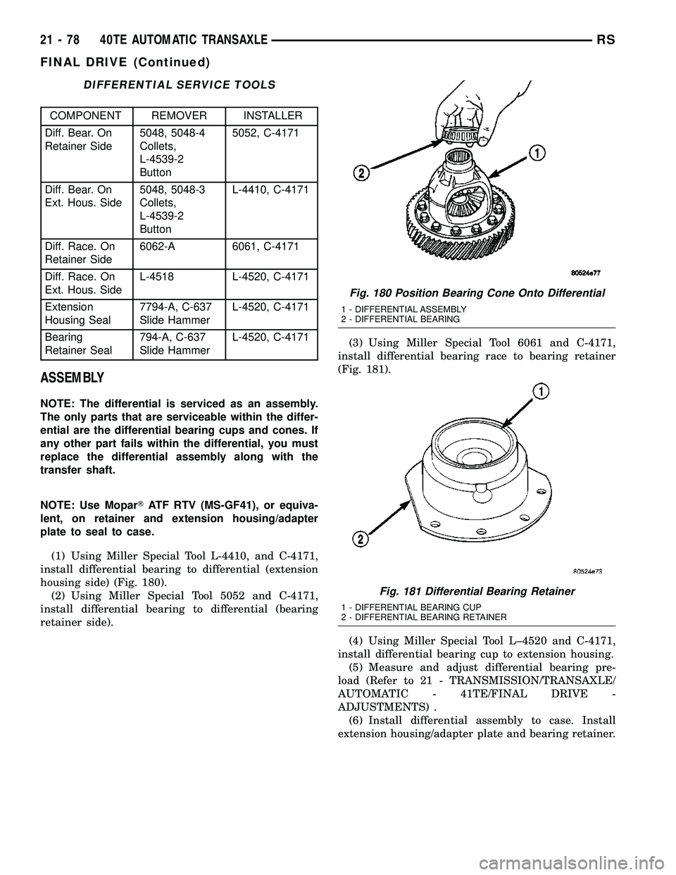
DIFFERENTIAL SERVICE TOOLS
COMPONENT REMOVER INSTALLER
Diff. Bear. On
Retainer Side5048, 5048-4
Collets,
L-4539-2
Button5052, C-4171
Diff. Bear. On
Ext. Hous. Side5048, 5048-3
Collets,
L-4539-2
ButtonL-4410, C-4171
Diff. Race. On
Retainer Side6062-A 6061, C-4171
Diff. Race. On
Ext. Hous. SideL-4518 L-4520, C-4171
Extension
Housing Seal7794-A, C-637
Slide HammerL-4520, C-4171
Bearing
Retainer Seal794-A, C-637
Slide HammerL-4520, C-4171
ASSEMBLY
NOTE: The differential is serviced as an assembly.
The only parts that are serviceable within the differ-
ential are the differential bearing cups and cones. If
any other part fails within the differential, you must
replace the differential assembly along with the
transfer shaft.
NOTE: Use MoparTATF RTV (MS-GF41), or equiva-
lent, on retainer and extension housing/adapter
plate to seal to case.
(1) Using Miller Special Tool L-4410, and C-4171,
install differential bearing to differential (extension
housing side) (Fig. 180).
(2) Using Miller Special Tool 5052 and C-4171,
install differential bearing to differential (bearing
retainer side).(3) Using Miller Special Tool 6061 and C-4171,
install differential bearing race to bearing retainer
(Fig. 181).
(4) Using Miller Special Tool L±4520 and C-4171,
install differential bearing cup to extension housing.
(5) Measure and adjust differential bearing pre-
load (Refer to 21 - TRANSMISSION/TRANSAXLE/
AUTOMATIC - 41TE/FINAL DRIVE -
ADJUSTMENTS) .
(6) Install differential assembly to case. Install
extension housing/adapter plate and bearing retainer.
Fig. 180 Position Bearing Cone Onto Differential
1 - DIFFERENTIAL ASSEMBLY
2 - DIFFERENTIAL BEARING
Fig. 181 Differential Bearing Retainer
1 - DIFFERENTIAL BEARING CUP
2 - DIFFERENTIAL BEARING RETAINER
21 - 78 40TE AUTOMATIC TRANSAXLERS
FINAL DRIVE (Continued)
Page 1540 of 2339

(7) Install bearing retainer with a bead of Mopart
ATF RTV (MS-GF41) and torque bolts (Fig. 182) to
28 N´m (250 in. lbs.).
(8) Install extension housing/adapter plate with a
bead of MopartATF RTV (MS-GF41) and torque
bolts to 28 N´m (250 in. lbs.).
(9) Install differential cover with a bead of Mopart
ATF RTV (MS-GF41) (Fig. 183) and torque bolts (Fig.
184) to 28 N´m (250 in. lbs.).
ADJUSTMENTS
DIFFERENTIAL BEARING PRELOAD
MEASUREMENT AND ADJUSTMENT
NOTE: Perform all differential bearing preload mea-
surements with the transfer shaft and gear
removed.
DIFFERENTIAL BEARING PRELOAD ADJUSTMENT USING
EXISTING SHIM
(1)
Position the transaxle assembly vertically on the
support stand, differential bearing retainer side up.
(2) Install Tool L-4436A into the differential and
onto the pinion mate shaft (Fig. 185).
Fig. 182 Differential Retainer Bolts
1 - DIFFERENTIAL RETAINER BOLTS
Fig. 183 Install Differential Cover
1 - DIFFERENTIAL ASSEMBLY
2 - DIFFERENTIAL COVER
Fig. 184 Differential Cover Bolts
1 - DIFFERENTIAL COVER BOLTS
2 - DIFFERENTIAL COVER
Fig. 185 Tool L-4436 and Torque Wrench
1 - SPECIAL TOOL L-4436±A
2 - TORQUE WRENCH
3 - DIFFERENTIAL BEARING RETAINER
RS40TE AUTOMATIC TRANSAXLE21-79
FINAL DRIVE (Continued)