Module CHRYSLER VOYAGER 2005 Service Manual
[x] Cancel search | Manufacturer: CHRYSLER, Model Year: 2005, Model line: VOYAGER, Model: CHRYSLER VOYAGER 2005Pages: 2339, PDF Size: 59.69 MB
Page 1 of 2339
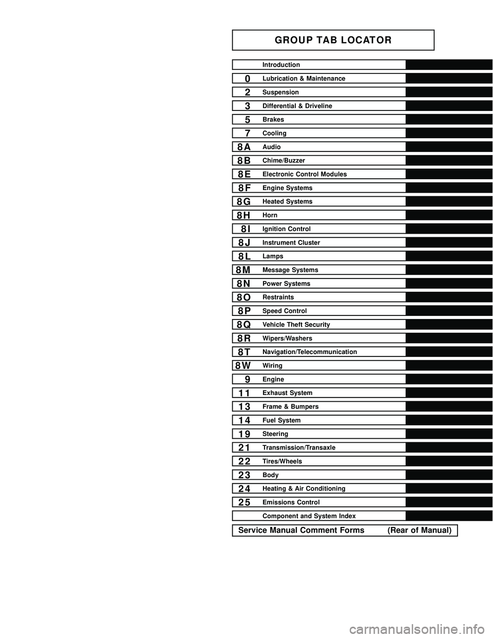
GROUP TAB LOCATOR
Introduction
0Lubrication & Maintenance
2Suspension
3Differential & Driveline
5Brakes
7Cooling
8AAudio
8BChime/Buzzer
8EElectronic Control Modules
8FEngine Systems
8GHeated Systems
8HHorn
8IIgnition Control
8JInstrument Cluster
8LLamps
8MMessage Systems
8NPower Systems
8ORestraints
8PSpeed Control
8QVehicle Theft Security
8RWipers/Washers
8TNavigation/Telecommunication
8WWiring
9Engine
11Exhaust System
13Frame & Bumpers
14Fuel System
19Steering
21Transmission/Transaxle
22Tires/Wheels
23Body
24Heating & Air Conditioning
25Emissions Control
Component and System Index
Service Manual Comment Forms (Rear of Manual)
Page 14 of 2339
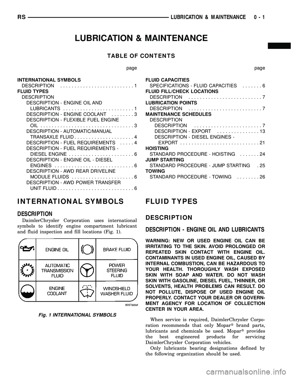
LUBRICATION & MAINTENANCE
TABLE OF CONTENTS
page page
INTERNATIONAL SYMBOLS
DESCRIPTION..........................1
FLUID TYPES
DESCRIPTION
DESCRIPTION - ENGINE OIL AND
LUBRICANTS.........................1
DESCRIPTION - ENGINE COOLANT........3
DESCRIPTION - FLEXIBLE FUEL ENGINE
OIL .................................3
DESCRIPTION - AUTOMATIC/MANUAL
TRANSAXLE FLUID.....................4
DESCRIPTION - FUEL REQUIREMENTS.....4
DESCRIPTION - FUEL REQUIREMENTS -
DIESEL ENGINE.......................6
DESCRIPTION - ENGINE OIL - DIESEL
ENGINES............................6
DESCRIPTION - AWD REAR DRIVELINE
MODULE FLUIDS......................6
DESCRIPTION - AWD POWER TRANSFER
UNIT FLUID...........................6FLUID CAPACITIES
SPECIFICATIONS - FLUID CAPACITIES.......6
FLUID FILL/CHECK LOCATIONS
DESCRIPTION..........................7
LUBRICATION POINTS
DESCRIPTION..........................7
MAINTENANCE SCHEDULES
DESCRIPTION
DESCRIPTION........................7
DESCRIPTION - EXPORT...............13
DESCRIPTION - DIESEL ENGINES -
EXPORT............................21
HOISTING
STANDARD PROCEDURE - HOISTING.......24
JUMP STARTING
STANDARD PROCEDURE - JUMP STARTING . 25
TOWING
STANDARD PROCEDURE - TOWING........26
INTERNATIONAL SYMBOLS
DESCRIPTION
DaimlerChrysler Corporation uses international
symbols to identify engine compartment lubricant
and fluid inspection and fill locations (Fig. 1).
FLUID TYPES
DESCRIPTION
DESCRIPTION - ENGINE OIL AND LUBRICANTS
WARNING: NEW OR USED ENGINE OIL CAN BE
IRRITATING TO THE SKIN. AVOID PROLONGED OR
REPEATED SKIN CONTACT WITH ENGINE OIL.
CONTAMINANTS IN USED ENGINE OIL, CAUSED BY
INTERNAL COMBUSTION, CAN BE HAZARDOUS TO
YOUR HEALTH. THOROUGHLY WASH EXPOSED
SKIN WITH SOAP AND WATER. DO NOT WASH
SKIN WITH GASOLINE, DIESEL FUEL, THINNER, OR
SOLVENTS, HEALTH PROBLEMS CAN RESULT. DO
NOT POLLUTE, DISPOSE OF USED ENGINE OIL
PROPERLY. CONTACT YOUR DEALER OR GOVERN-
MENT AGENCY FOR LOCATION OF COLLECTION
CENTER IN YOUR AREA.
When service is required, DaimlerChrysler Corpo-
ration recommends that only Mopartbrand parts,
lubricants and chemicals be used. Mopartprovides
the best engineered products for servicing
DaimlerChrysler Corporation vehicles.
Only lubricants bearing designations defined by
the following organization should be used.
Fig. 1 INTERNATIONAL SYMBOLS
RSLUBRICATION & MAINTENANCE0-1
Page 19 of 2339
DESCRIPTION - FUEL REQUIREMENTS -
DIESEL ENGINE
WARNING: DO NOT USE ALCOHOL OR GASOLINE
AS A FUEL BLENDING AGENT. THEY CAN BE
UNSTABLE UNDER CERTAIN CONDITIONS AND
HAZARDOUS OR EXPLOSIVE WHEN MIXED WITH
DIESEL FUEL.
Use good quality diesel fuel from a reputable sup-
plier. For most year-round service, number 2 diesel
fuel meeting DIN EN 590 (Class0-4)will provide
good performance. If the vehicle is exposed to
extreme cold (below -18ÉC/0ÉF) or is required to oper-
ate at colder than normal conditions for prolonged
periods, use climatize No. 2 diesel fuel or dilute the
No. 2 diesel fuel with 50% No. 1 diesel fuel as long as
it meets ASTM D 975: 1D and 2D and the quality of
lubrication behavior is in accordance with DIN EN
590. This will provide better protection from fuel gel-
ling or wax plugging of the fuel filters.
Diesel fuel is seldom completely free of water. To
prevent fuel system trouble, including fuel line freez-
ing in winter, drain the accumulated water from the
fuel/water separator using the fuel/water separator
drain provided. If you buy good quality fuel and follow
the cold weather advice above, fuel conditioners should
not be required in your vehicle. If available in your
area, a high cetane ªpremiumº diesel fuel may offer
improved cold starting and warm up performance.
DESCRIPTION - ENGINE OIL - DIESEL
ENGINES
Use only Diesel Engine Oil meeting standardMIL-
2104Cor API ClassificationCD or higherorCCML
D4, D5.
SAE VISCOSITY GRADE
CAUTION: Low viscosity oils must have the proper
API quality or the CCMC G5 designation.
To assure of properly formulated engine oils, it is
recommended that SAE Grade 10W-40 engine oils
that meet Chrysler material standard MS-6395, be
used in accordance to ACEA B3, B4 specification.
European Grade 10W-40 oils are also acceptable.
Oils of the SAE 5W-40 grade number are preferred
when minimum temperatures consistently fall below
-15ÉC.
DESCRIPTION - AWD REAR DRIVELINE
MODULE FLUIDS
The AWD Rear Driveline Module Assembly consists
of two subassemblies, the Overrunning Clutch Hous-
ing (front) and the Differential Carrier (rear).The recommended lubricant for the Overrunning
Clutch Housing is MopartATF+4. The recommended
lubricant for the Differential Carrier is Mopart
80W-90 Gear and Axle Lubricant.
DESCRIPTION - AWD POWER TRANSFER UNIT
FLUID
The recommended lubricant for the AWD Power
Transfer Unit is MopartGear and Axle Lubricant
80W-90.
FLUID CAPACITIES
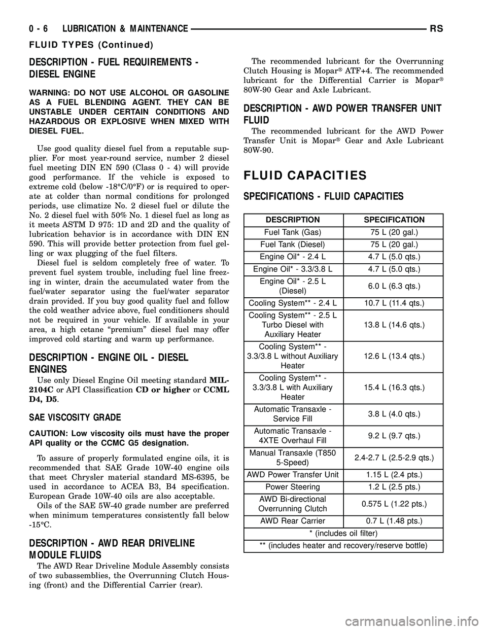
SPECIFICATIONS - FLUID CAPACITIES
DESCRIPTION SPECIFICATION
Fuel Tank (Gas) 75 L (20 gal.)
Fuel Tank (Diesel) 75 L (20 gal.)
Engine Oil* - 2.4 L 4.7 L (5.0 qts.)
Engine Oil* - 3.3/3.8 L 4.7 L (5.0 qts.)
Engine Oil* - 2.5 L
(Diesel)6.0 L (6.3 qts.)
Cooling System** - 2.4 L 10.7 L (11.4 qts.)
Cooling System** - 2.5 L
Turbo Diesel with
Auxiliary Heater13.8 L (14.6 qts.)
Cooling System** -
3.3/3.8 L without Auxiliary
Heater12.6 L (13.4 qts.)
Cooling System** -
3.3/3.8 L with Auxiliary
Heater15.4 L (16.3 qts.)
Automatic Transaxle -
Service Fill3.8 L (4.0 qts.)
Automatic Transaxle -
4XTE Overhaul Fill9.2 L (9.7 qts.)
Manual Transaxle (T850
5-Speed)2.4-2.7 L (2.5-2.9 qts.)
AWD Power Transfer Unit 1.15 L (2.4 pts.)
Power Steering 1.2 L (2.5 pts.)
AWD Bi-directional
Overrunning Clutch0.575 L (1.22 pts.)
AWD Rear Carrier 0.7 L (1.48 pts.)
* (includes oil filter)
** (includes heater and recovery/reserve bottle)
0 - 6 LUBRICATION & MAINTENANCERS
FLUID TYPES (Continued)
Page 63 of 2339
WARNING: DO NOT REMOVE THE STRUT SHAFT
NUT BEFORE THE COIL SPRING IS COMPRESSED.
THE COIL SPRING IS HELD UNDER PRESSURE
AND MUST BE COMPRESSED, REMOVING SPRING
TENSION FROM THE UPPER MOUNT AND PIVOT
BEARING, BEFORE THE SHAFT NUT IS REMOVED.
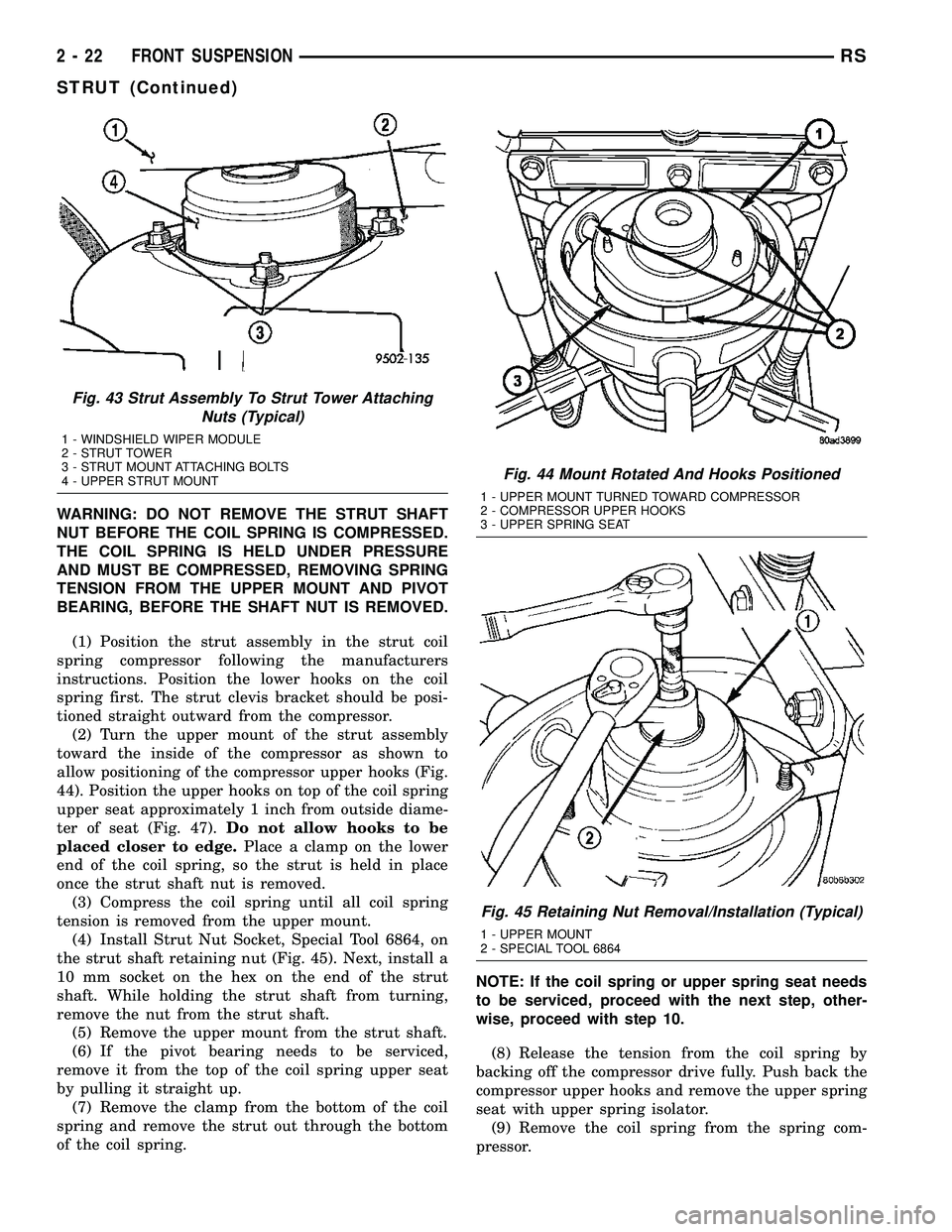
(1) Position the strut assembly in the strut coil
spring compressor following the manufacturers
instructions. Position the lower hooks on the coil
spring first. The strut clevis bracket should be posi-
tioned straight outward from the compressor.
(2) Turn the upper mount of the strut assembly
toward the inside of the compressor as shown to
allow positioning of the compressor upper hooks (Fig.
44). Position the upper hooks on top of the coil spring
upper seat approximately 1 inch from outside diame-
ter of seat (Fig. 47).Do not allow hooks to be
placed closer to edge.Place a clamp on the lower
end of the coil spring, so the strut is held in place
once the strut shaft nut is removed.
(3) Compress the coil spring until all coil spring
tension is removed from the upper mount.
(4) Install Strut Nut Socket, Special Tool 6864, on
the strut shaft retaining nut (Fig. 45). Next, install a
10 mm socket on the hex on the end of the strut
shaft. While holding the strut shaft from turning,
remove the nut from the strut shaft.
(5) Remove the upper mount from the strut shaft.
(6) If the pivot bearing needs to be serviced,
remove it from the top of the coil spring upper seat
by pulling it straight up.
(7) Remove the clamp from the bottom of the coil
spring and remove the strut out through the bottom
of the coil spring.NOTE: If the coil spring or upper spring seat needs
to be serviced, proceed with the next step, other-
wise, proceed with step 10.
(8) Release the tension from the coil spring by
backing off the compressor drive fully. Push back the
compressor upper hooks and remove the upper spring
seat with upper spring isolator.
(9) Remove the coil spring from the spring com-
pressor.
Fig. 43 Strut Assembly To Strut Tower Attaching
Nuts (Typical)
1 - WINDSHIELD WIPER MODULE
2 - STRUT TOWER
3 - STRUT MOUNT ATTACHING BOLTS
4 - UPPER STRUT MOUNT
Fig. 44 Mount Rotated And Hooks Positioned
1 - UPPER MOUNT TURNED TOWARD COMPRESSOR
2 - COMPRESSOR UPPER HOOKS
3 - UPPER SPRING SEAT
Fig. 45 Retaining Nut Removal/Installation (Typical)
1 - UPPER MOUNT
2 - SPECIAL TOOL 6864
2 - 22 FRONT SUSPENSIONRS
STRUT (Continued)
Page 73 of 2339
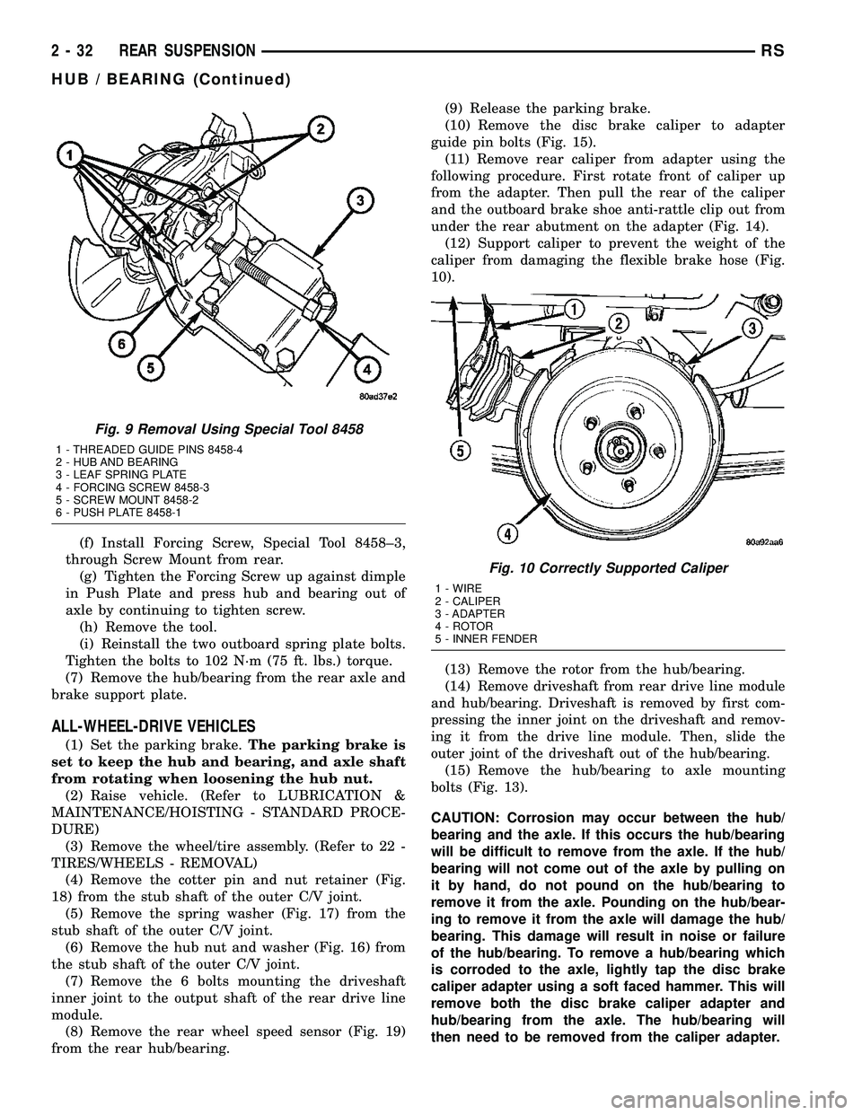
(f) Install Forcing Screw, Special Tool 8458±3,
through Screw Mount from rear.
(g) Tighten the Forcing Screw up against dimple
in Push Plate and press hub and bearing out of
axle by continuing to tighten screw.
(h) Remove the tool.
(i) Reinstall the two outboard spring plate bolts.
Tighten the bolts to 102 N´m (75 ft. lbs.) torque.
(7) Remove the hub/bearing from the rear axle and
brake support plate.
ALL-WHEEL-DRIVE VEHICLES
(1) Set the parking brake.The parking brake is
set to keep the hub and bearing, and axle shaft
from rotating when loosening the hub nut.
(2) Raise vehicle. (Refer to LUBRICATION &
MAINTENANCE/HOISTING - STANDARD PROCE-
DURE)
(3) Remove the wheel/tire assembly. (Refer to 22 -
TIRES/WHEELS - REMOVAL)
(4) Remove the cotter pin and nut retainer (Fig.
18) from the stub shaft of the outer C/V joint.
(5) Remove the spring washer (Fig. 17) from the
stub shaft of the outer C/V joint.
(6) Remove the hub nut and washer (Fig. 16) from
the stub shaft of the outer C/V joint.
(7) Remove the 6 bolts mounting the driveshaft
inner joint to the output shaft of the rear drive line
module.
(8) Remove the rear wheel speed sensor (Fig. 19)
from the rear hub/bearing.(9) Release the parking brake.
(10) Remove the disc brake caliper to adapter
guide pin bolts (Fig. 15).
(11) Remove rear caliper from adapter using the
following procedure. First rotate front of caliper up
from the adapter. Then pull the rear of the caliper
and the outboard brake shoe anti-rattle clip out from
under the rear abutment on the adapter (Fig. 14).
(12) Support caliper to prevent the weight of the
caliper from damaging the flexible brake hose (Fig.
10).
(13) Remove the rotor from the hub/bearing.
(14)
Remove driveshaft from rear drive line module
and hub/bearing. Driveshaft is removed by first com-
pressing the inner joint on the driveshaft and remov-
ing it from the drive line module. Then, slide the
outer joint of the driveshaft out of the hub/bearing.
(15) Remove the hub/bearing to axle mounting
bolts (Fig. 13).
CAUTION: Corrosion may occur between the hub/
bearing and the axle. If this occurs the hub/bearing
will be difficult to remove from the axle. If the hub/
bearing will not come out of the axle by pulling on
it by hand, do not pound on the hub/bearing to
remove it from the axle. Pounding on the hub/bear-
ing to remove it from the axle will damage the hub/
bearing. This damage will result in noise or failure
of the hub/bearing. To remove a hub/bearing which
is corroded to the axle, lightly tap the disc brake
caliper adapter using a soft faced hammer. This will
remove both the disc brake caliper adapter and
hub/bearing from the axle. The hub/bearing will
then need to be removed from the caliper adapter.
Fig. 9 Removal Using Special Tool 8458
1 - THREADED GUIDE PINS 8458-4
2 - HUB AND BEARING
3 - LEAF SPRING PLATE
4 - FORCING SCREW 8458-3
5 - SCREW MOUNT 8458-2
6 - PUSH PLATE 8458-1
Fig. 10 Correctly Supported Caliper
1 - WIRE
2 - CALIPER
3 - ADAPTER
4 - ROTOR
5 - INNER FENDER
2 - 32 REAR SUSPENSIONRS
HUB / BEARING (Continued)
Page 75 of 2339
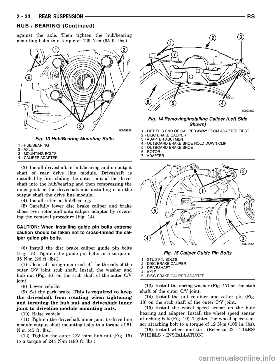
against the axle. Then tighten the hub/bearing
mounting bolts to a torque of 129 N´m (95 ft. lbs.).
(3) Install driveshaft in hub/bearing and on output
shaft of rear drive line module. Driveshaft is
installed by first sliding the outer joint of the drive-
shaft into the hub/bearing and then compressing the
inner joint on the driveshaft and installing it on the
output shaft the drive line module.
(4) Install rotor on hub/bearing.
(5) Carefully lower disc brake caliper and brake
shoes over rotor and onto caliper adapter by revers-
ing the removal procedure (Fig. 14).
CAUTION: When installing guide pin bolts extreme
caution should be taken not to cross-thread the cal-
iper guide pin bolts.
(6) Install the disc brake caliper guide pin bolts
(Fig. 15). Tighten the guide pin bolts to a torque of
35 N´m (26 ft. lbs.).
(7) Clean all foreign material off the threads of the
outer C/V joint stub shaft. Install the washer and
hub nut (Fig. 16) on the stub shaft of the outer C/V
joint.
(8) Lower vehicle.
(9) Set the park brake.This is required to keep
the driveshaft from rotating when tightening
and torquing the hub nut and driveshaft inner
joint to driveline module mounting nuts.
(10) Raise vehicle.
(11) Tighten the driveshaft inner joint to drive line
module output shaft mounting bolts to a torque of 61
N´m (45 ft. lbs.).
(12) Tighten the outer C/V joint hub nut (Fig. 16)
to a torque of 244 N´m (180 ft. lbs.).(13) Install the spring washer (Fig. 17) on the stub
shaft of the outer C/V joint.
(14) Install the nut retainer and cotter pin (Fig.
18) on the stub shaft of the outer C/V joint.
(15) Install the wheel speed sensor on the hub/
bearing and adapter. Install the wheel speed sensor
attaching bolt (Fig. 19). Tighten the wheel speed sen-
sor attaching bolt to a torque of 12 N´m (105 in. lbs).
(16) Install wheel and tire. (Refer to 22 - TIRES/
WHEELS - INSTALLATION)
Fig. 13 Hub/Bearing Mounting Bolts
1 - HUB/BEARING
2 - AXLE
3 - MOUNTING BOLTS
4 - CALIPER ADAPTER
Fig. 14 Removing/Installing Caliper (Left Side
Shown)
1 - LIFT THIS END OF CALIPER AWAY FROM ADAPTER FIRST
2 - DISC BRAKE CALIPER
3 - ADAPTER ABUTMENT
4 - OUTBOARD BRAKE SHOE HOLD DOWN CLIP
5 - OUTBOARD BRAKE SHOE
6 - ROTOR
7 - ADAPTER
Fig. 15 Caliper Guide Pin Bolts
1 - STUD PIN BOLTS
2 - DISC BRAKE CALIPER
3 - DRIVESHAFT
4 - AXLE
5 - DISC BRAKE CALIPER ADAPTER
2 - 34 REAR SUSPENSIONRS
HUB / BEARING (Continued)
Page 120 of 2339

Follow pressure bleeder manufacturer's instruc-
tions for use of pressure bleeding equipment.
(1) Install the Adapter Master Cylinder Pressure
Bleed Cap, Special Tool 6921 on the fluid reservoir of
the master cylinder (Fig. 2). Attach the fluid hose
from the pressure bleeder to the fitting on Special
Tool 6921.
(2) Attach a clear plastic hose to the bleeder screw
at one wheel and feed the hose into a clear jar con-
taining fresh brake fluid.
(3) Open the left rear wheel bleeder screw at least
one full turnor more to obtain an adequate flow of
brake fluid.
CAUTION: ªJust crackingº the bleeder screw often
restricts fluid flow, allowing only a slow, weak fluid
discharge of fluid. This practice will NOT get all the
air out. Make sure the bleeder is opened at least 1
full turn when bleeding.
(4) After 4 to 8 ounces of brake fluid has been bled
through the hydraulic system, and an air-free flow is
maintained in the hose and jar, this will indicate a
good bleed of the hydraulic system has been
obtained.
(5) Repeat the procedure at all the other remain-
ing bleeder screws.
(6) Check pedal travel. If pedal travel is excessive
or has not been improved, enough fluid has not
passed through the system to expel all the trapped
air. Be sure to monitor the fluid level in the pressure
bleeder, so it stays at a proper level so air will not
enter the brake system through the master cylinder.
(7) Perform a final adjustment of the rear brake
shoes (when applicable), then test drive vehicle to be
sure brakes are operating correctly and that pedal is
solid.SPECIFICATIONS
BRAKE FASTENER TORQUE
DESCRIPTION N´mFt.
Lbs.In.
Lbs.
ABS ICU Mounting Bolts To
Bracket11 Ð 9 7
ABS ICU Mounting
Bracket-To-Cradle Bolts28 21 250
ABS CAB-To-HCU Mounting
Screws2Ð17
ABS Wheel Speed Sensor
Head Mounting Bolt - Front13 Ð 115
ABS Wheel Speed Sensor
Head Mounting Bolt - Rear10 Ð 90
Adjustable Pedal Position
Sensor Mounting Screws7.5 66 Ð
Adjustable Pedal Module
Mounting Screws2.0 15 Ð
Brake Tube Nuts 17 Ð 145
Brake Hose Intermediate
Bracket Bolt12 Ð 105
Brake Hose-To-Caliper
Mounting Bolt47 35 Ð
Disc Brake Caliper Guide
Pin Bolts35 26 Ð
Disc Brake Caliper Bleeder
Screw15 Ð 125
Drum Brake Wheel Cylinder
Mounting Bolts8Ð75
Drum Brake Wheel Cylinder
Mounting Bleeder screw10 Ð 80
Drum Brake Support Plate
Mounting Bolts130 95 Ð
Junction Block (Non-ABS
Brakes) Mounting Bolts28 21 250
Master Cylinder Mounting
Nuts25 19 225
Power Brake Booster
Mounting Nuts28 21 250
Proportioning Valve
Mounting Bolts54 40 Ð
Proportioning Valve Axle
Bracket Mounting Bolt20 Ð 175
Parking Brake Lever (Pedal)
Mounting Bolts And Nut28 21 250
Wheel Mounting (Lug) Nuts 135 100 Ð
Fig. 2 Tool 6921 Installed On Master Cylinder
1 - SPECIAL TOOL 6921
2 - FLUID RESERVOIR
RSBRAKES - BASE5-9
BRAKES - BASE (Continued)
Page 152 of 2339
(12) Disconnect wiring harness connectors (as
equipped) from clockspring, multi-function switch,
SKIM module, ignition switch and BTSI solenoid.
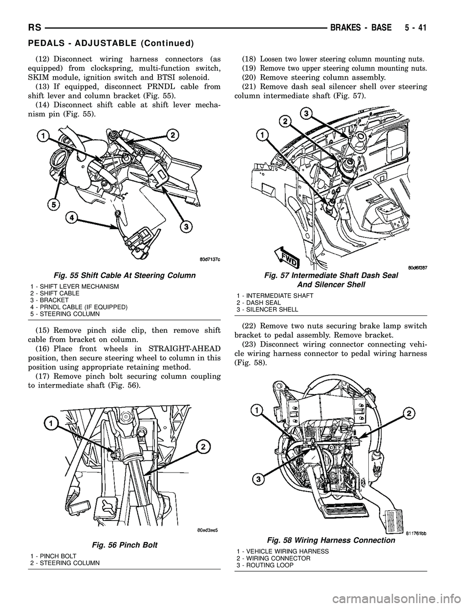
(13) If equipped, disconnect PRNDL cable from
shift lever and column bracket (Fig. 55).
(14) Disconnect shift cable at shift lever mecha-
nism pin (Fig. 55).
(15) Remove pinch side clip, then remove shift
cable from bracket on column.
(16) Place front wheels in STRAIGHT-AHEAD
position, then secure steering wheel to column in this
position using appropriate retaining method.
(17) Remove pinch bolt securing column coupling
to intermediate shaft (Fig. 56).(18)Loosen two lower steering column mounting nuts.
(19)Remove two upper steering column mounting nuts.
(20) Remove steering column assembly.
(21) Remove dash seal silencer shell over steering
column intermediate shaft (Fig. 57).
(22) Remove two nuts securing brake lamp switch
bracket to pedal assembly. Remove bracket.
(23) Disconnect wiring connector connecting vehi-
cle wiring harness connector to pedal wiring harness
(Fig. 58).
Fig. 55 Shift Cable At Steering Column
1 - SHIFT LEVER MECHANISM
2 - SHIFT CABLE
3 - BRACKET
4 - PRNDL CABLE (IF EQUIPPED)
5 - STEERING COLUMN
Fig. 56 Pinch Bolt
1 - PINCH BOLT
2 - STEERING COLUMN
Fig. 57 Intermediate Shaft Dash Seal
And Silencer Shell
1 - INTERMEDIATE SHAFT
2 - DASH SEAL
3 - SILENCER SHELL
Fig. 58 Wiring Harness Connection
1 - VEHICLE WIRING HARNESS
2 - WIRING CONNECTOR
3 - ROUTING LOOP
RSBRAKES - BASE5-41
PEDALS - ADJUSTABLE (Continued)
Page 154 of 2339
INSTALLATION
(1) Install adjustable pedals assembly under
instrument panel.
(2) Attach throttle cable to accelerator pedal using
cable retainer.
(3) Install two upper mounting bolts attaching
pedals assembly to steering column support bracket
on dash panel.Do not fully tighten at this time.
(4) Install four nuts attaching pedals assembly and
power brake booster to dash panel (Fig. 61).
(5) Tighten four booster mounting nuts and two
upper mounting bolts to 28 N´m (21 ft. lbs.) torque.
(6) Route pedal adjuster cable up and over right
side of pedals assembly and steering column bracket,
then down through hole in steering column bracket
as shown (Fig. 60). Attach end of cable to gear box.
(7) Place adjuster cable through loop on right side
of steering column bracket as shown (Fig. 60).
(8) Install booster input rod onto brake pedal pin
and install a NEW retaining clip.
(9) Connect wiring connector connecting vehicle
wiring harness to pedal wiring harness (Fig. 58).
(10) Connect routing clips retaining vehicle wiring
harness to pedal wiring harness (Fig. 58).
(11) Install brake lamp switch bracket on pedals
assembly. Tighten mounting nuts to 6 N´m (50 in.
lbs.) torque.
(12) Install dash seal silencer shell over steering
column intermediate shaft and fasten in place (Fig.
57).
(13) Install steering column onto lower mounting
studs with nuts started, then install column onto
upper mounting studs and install two upper mount-
ing nuts. Tighten upper, then lower mounting nuts to
12 N´m (105 in. lbs.) torque.
(14) Install column shaft coupling onto intermedi-
ate shaft and install pinch bolt. Make sure rounded
side of intermediate shaft is matched to the curva-
ture of the coupling. Tighten pinch bolt to 28 N´m
(250 in. lbs.) torque.
(15) Remove retainer holding steering wheel in
place on steering column.
(16) Attach shift cable to bracket on column.
(17) Connect shift cable end to shift lever mecha-
nism pin (Fig. 55).
(18) If equipped, connect PRNDL cable to end of
shift lever mechanism pin and column bracket (Fig.
55).(19) Connect column wiring harness connectors (as
equipped) to SKIM, BTSI solenoid, ignition switch,
multi-function switch, and clockspring.
(20) Install lower and upper steering column
shrouds. (Refer to 19 - STEERING/COLUMN/
LOWER SHROUD - INSTALLATION)
CAUTION: Do not reuse the original brake lamp
switch. The switch can only be adjusted once. That
is during initial installation of the switch. If the
switch is not adjusted properly or has been
removed for some service, a new switch must be
installed and adjusted.
(21) Install and adjust NEW brake lamp switch.
(Refer to 8 - ELECTRICAL/LAMPS/LIGHTING -
EXTERIOR/BRAKE LAMP SWITCH - INSTALLA-
TION)
(22) Install instrument panel lower left reinforce-
ment (Fig. 54).
(23) Attach hood release to lower left reinforce-
ment.
(24) Install knee blocker reinforcement plate (Fig.
53).
(25) Connect parking brake release link to release
handle.
(26) Install data link diagnostic connector to
mounting hole in reinforcement plate.
(27) Install lower steering column cover/knee
blocker (Fig. 53).
(28) Install throttle cable onto throttle body lever.
(Refer to 14 - FUEL SYSTEM/FUEL INJECTION/
THROTTLE CONTROL CABLE - INSTALLATION)
NOTE: When reconnecting the battery on a vehicle
that has had the airbag module removed, the fol-
lowing procedure should be used.
(29) Reconnect ground cable to negative post of
battery following special Diagnosis And Testing pro-
cedure. (Refer to 8 - ELECTRICAL/RESTRAINTS -
DIAGNOSIS AND TESTING)
(30) Test operation of adjustable pedals and all
functions that are steering column operated. If appli-
cable, reset radio and clock.
(31) Road test the vehicle to ensure proper opera-
tion of steering and brake systems.
RSBRAKES - BASE5-43
PEDALS - ADJUSTABLE (Continued)
Page 158 of 2339

(6) Remove screw securing engine coolant filler
tube to battery tray.
(7) If the vehicle is equipped with speed control,
disconnect the vacuum hose at the vacuum tank built
into the battery tray.
(8) Remove the two nuts and one bolt securing bat-
tery tray in place. Remove battery tray.
(9) If vehicle is equipped with speed control:
(a) Disconnect wiring harness connector from
the speed control servo.
(b) Remove the two servo mounting nuts.
(c) Lay speed control servo off to the side, out of
the way.
(10) Remove the wiper module (unit). (Refer to 8 -
ELECTRICAL/WIPERS/WASHERS/WIPER MOD-
ULE - REMOVAL)
(11) Disconnect wiring harness connector from
brake fluid level switch in master cylinder fluid res-
ervoir (Fig. 66).
CAUTION: Before removing the master cylinder
from the power brake vacuum booster, the master
cylinder and vacuum booster must be thoroughly
cleaned. This must be done to prevent dirt particles
from falling into the power brake vacuum booster.
(12) Clean area where master cylinder assembly
attaches to power brake booster. Use only a solvent
such as MopartBrake Parts Cleaner or equivalent.(13) Disconnect primary and secondary brake
tubes from ABS integrated control unit or non-ABS
junction block (Fig. 67). Install sealing plugs in the
now open brake tube ports and install caps on ends
of tubes.
NOTE: It is not necessary to remove the brake
tubes from the master cylinder when removing the
master cylinder from the vacuum booster.
(14) Remove two nuts attaching master cylinder to
power brake booster (Fig. 67).
(15) Slide master cylinder straight out of power
brake booster. Remove master cylinder with primary
and secondary tubes from vehicle.
CAUTION: A seal on the rear of the master cylinder
is used to create the seal for holding vacuum in the
power brake vacuum booster. The vacuum seal on
the master cylinder MUST be replaced whenever the
master cylinder is removed from the power brake
vacuum booster.
(16) Disconnect vacuum hose from check valve
located on vacuum booster.DO NOT REMOVE
CHECK VALVE FROM POWER BRAKE
BOOSTER.
Fig. 66 Master Cylinder And Booster
1 - POWER BRAKE BOOSTER
2 - BOOSTER IDENTIFICATION LABEL
3 - FLUID LEVEL SWITCH CONNECTOR
4 - PRIMARY BRAKE TUBE NUT
5 - SECONDARY BRAKE TUBE NUT
6 - MASTER CYLINDER
Fig. 67 Master Cylinder Mounting
1 - MASTER CYLINDER MOUNTING NUTS
2 - MASTER CYLINDER
3 - SECONDARY TUBE NUT AT ICU
4 - PRIMARY TUBE NUT AT ICU
RSBRAKES - BASE5-47
POWER BRAKE BOOSTER (Continued)