ESP CHRYSLER VOYAGER 2005 User Guide
[x] Cancel search | Manufacturer: CHRYSLER, Model Year: 2005, Model line: VOYAGER, Model: CHRYSLER VOYAGER 2005Pages: 2339, PDF Size: 59.69 MB
Page 32 of 2339
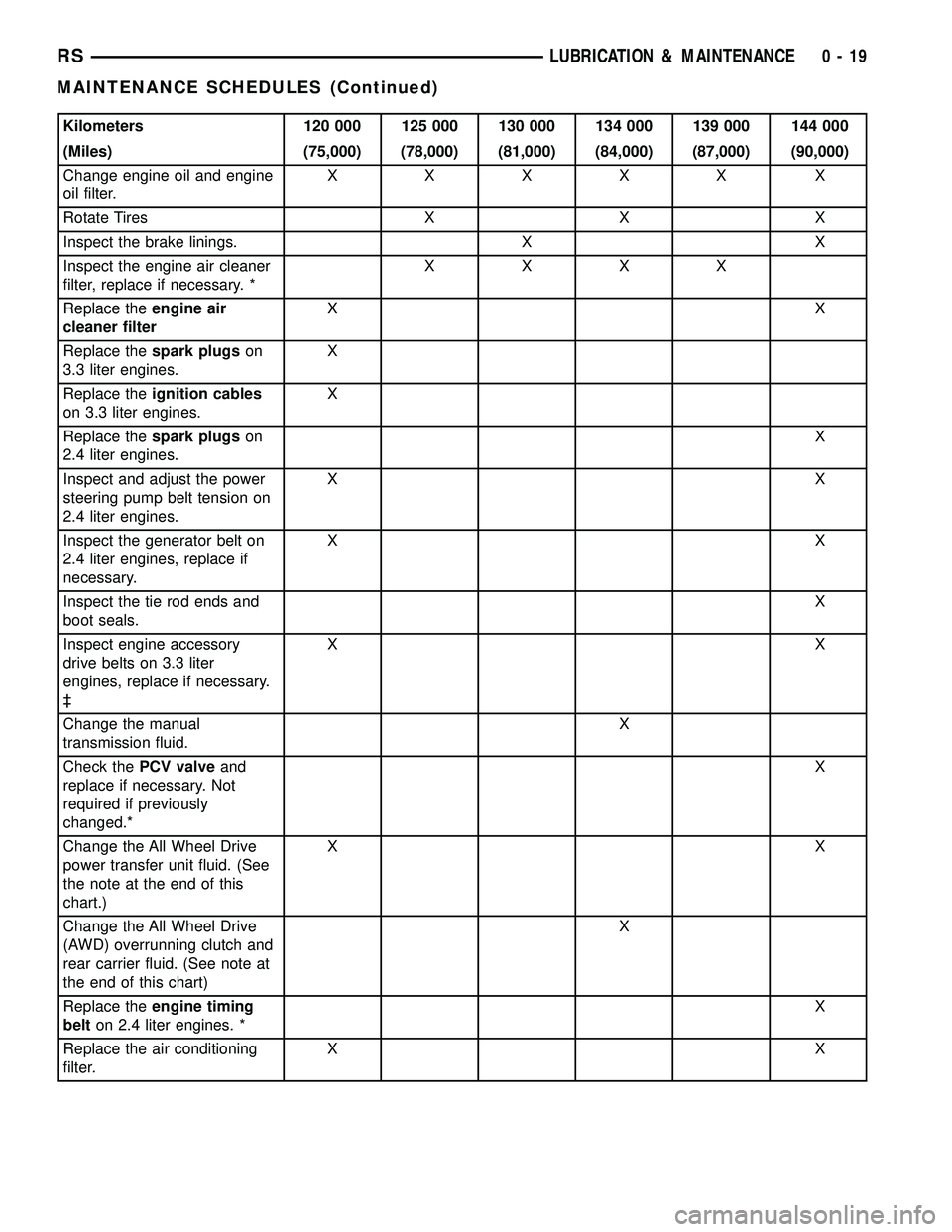
Kilometers 120 000 125 000 130 000 134 000 139 000 144 000
(Miles) (75,000) (78,000) (81,000) (84,000) (87,000) (90,000)
Change engine oil and engine
oil filter.XXXXX X
Rotate Tires X X X
Inspect the brake linings. X X
Inspect the engine air cleaner
filter, replace if necessary. *XXXX
Replace theengine air
cleaner filterXX
Replace thespark plugson
3.3 liter engines.X
Replace theignition cables
on 3.3 liter engines.X
Replace thespark plugson
2.4 liter engines.X
Inspect and adjust the power
steering pump belt tension on
2.4 liter engines.XX
Inspect the generator belt on
2.4 liter engines, replace if
necessary.XX
Inspect the tie rod ends and
boot seals.X
Inspect engine accessory
drive belts on 3.3 liter
engines, replace if necessary.
³XX
Change the manual
transmission fluid.X
Check thePCV valveand
replace if necessary. Not
required if previously
changed.*X
Change the All Wheel Drive
power transfer unit fluid. (See
the note at the end of this
chart.)XX
Change the All Wheel Drive
(AWD) overrunning clutch and
rear carrier fluid. (See note at
the end of this chart)X
Replace theengine timing
belton 2.4 liter engines. *X
Replace the air conditioning
filter.XX
RSLUBRICATION & MAINTENANCE0-19
MAINTENANCE SCHEDULES (Continued)
Page 33 of 2339
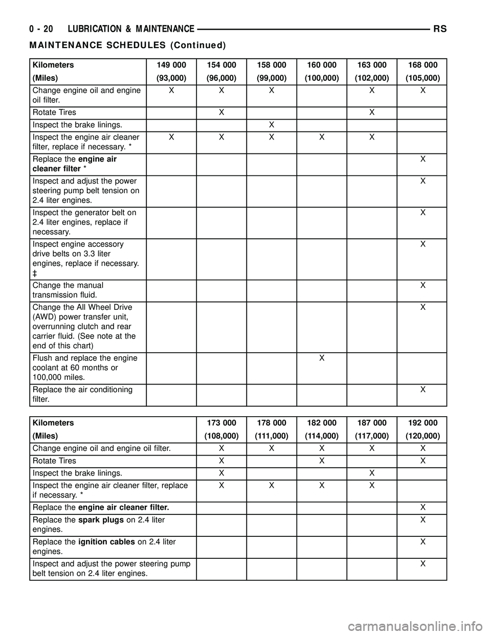
Kilometers 149 000 154 000 158 000 160 000 163 000 168 000
(Miles) (93,000) (96,000) (99,000) (100,000) (102,000) (105,000)
Change engine oil and engine
oil filter.XXX X X
Rotate Tires X X
Inspect the brake linings. X
Inspect the engine air cleaner
filter, replace if necessary. *XXXXX
Replace theengine air
cleaner filter*X
Inspect and adjust the power
steering pump belt tension on
2.4 liter engines.X
Inspect the generator belt on
2.4 liter engines, replace if
necessary.X
Inspect engine accessory
drive belts on 3.3 liter
engines, replace if necessary.
³X
Change the manual
transmission fluid.X
Change the All Wheel Drive
(AWD) power transfer unit,
overrunning clutch and rear
carrier fluid. (See note at the
end of this chart)X
Flush and replace the engine
coolant at 60 months or
100,000 miles.X
Replace the air conditioning
filter.X
Kilometers 173 000 178 000 182 000 187 000 192 000
(Miles) (108,000) (111,000) (114,000) (117,000) (120,000)
Change engine oil and engine oil filter.XXXX X
Rotate Tires X X X
Inspect the brake linings. X X
Inspect the engine air cleaner filter, replace
if necessary. *XXXX
Replace theengine air cleaner filter.X
Replace thespark plugson 2.4 liter
engines.X
Replace theignition cableson 2.4 liter
engines.X
Inspect and adjust the power steering pump
belt tension on 2.4 liter engines.X
0 - 20 LUBRICATION & MAINTENANCERS
MAINTENANCE SCHEDULES (Continued)
Page 115 of 2339
WARNING
WARNING: DUST AND DIRT ACCUMULATING ON
BRAKE PARTS DURING NORMAL USE MAY CON-
TAIN ASBESTOS FIBERS FROM PRODUCTION OR
AFTERMARKET BRAKE LININGS. BREATHING
EXCESSIVE CONCENTRATIONS OF ASBESTOS
FIBERS CAN CAUSE SERIOUS BODILY HARM.
EXERCISE CARE WHEN SERVICING BRAKE
PARTS. DO NOT SAND OR GRIND BRAKE LINING
UNLESS EQUIPMENT USED IS DESIGNED TO CON-
TAIN THE DUST RESIDUE. DO NOT CLEAN BRAKE
PARTS WITH COMPRESSED AIR OR BY DRY
BRUSHING. CLEANING SHOULD BE DONE BY
DAMPENING THE BRAKE COMPONENTS WITH A
FINE MIST OF WATER, THEN WIPING THE BRAKE
COMPONENTS CLEAN WITH A DAMPENED CLOTH.
DISPOSE OF CLOTH AND ALL RESIDUE CONTAIN-
ING ASBESTOS FIBERS IN AN IMPERMEABLE
CONTAINER WITH THE APPROPRIATE LABEL. FOL-
LOW PRACTICES PRESCRIBED BY THE OCCUPA-
TIONAL SAFETY AND HEALTH ADMINISTRATION
(OSHA) AND THE ENVIRONMENTAL PROTECTION
AGENCY (EPA) FOR THE HANDLING, PROCESSING,
AND DISPOSING OF DUST OR DEBRIS THAT MAY
CONTAIN ASBESTOS FIBERS.
CAUTION
CAUTION: During service procedures, grease or
any other foreign material must be kept off brake
shoes and braking surfaces of brake rotor or drum,
and external surfaces of hub and bearing assembly.
CAUTION: Brake rotor and caliper handling must be
done in such a way as to avoid damage to the rotor,
especially the machined surfaces, and scratching or
nicking of the brake linings.
CAUTION: Only the recommended jacking or hoist-
ing procedures for this vehicle are to be used
whenever it is necessary to lift a vehicle. Failure to
raise a vehicle utilizing the recommended lift points
can result in damage to the vehicle. (Refer to
LUBRICATION & MAINTENANCE/HOISTING - STAN-
DARD PROCEDURE)
DIAGNOSIS AND TESTING - BASE BRAKE
SYSTEM
NOTE: There are three diagnosis charts following
that cover the RED BRAKE WARNING INDICATOR
LAMP, BRAKE NOISE and OTHER BRAKE CONDI-
TIONS.
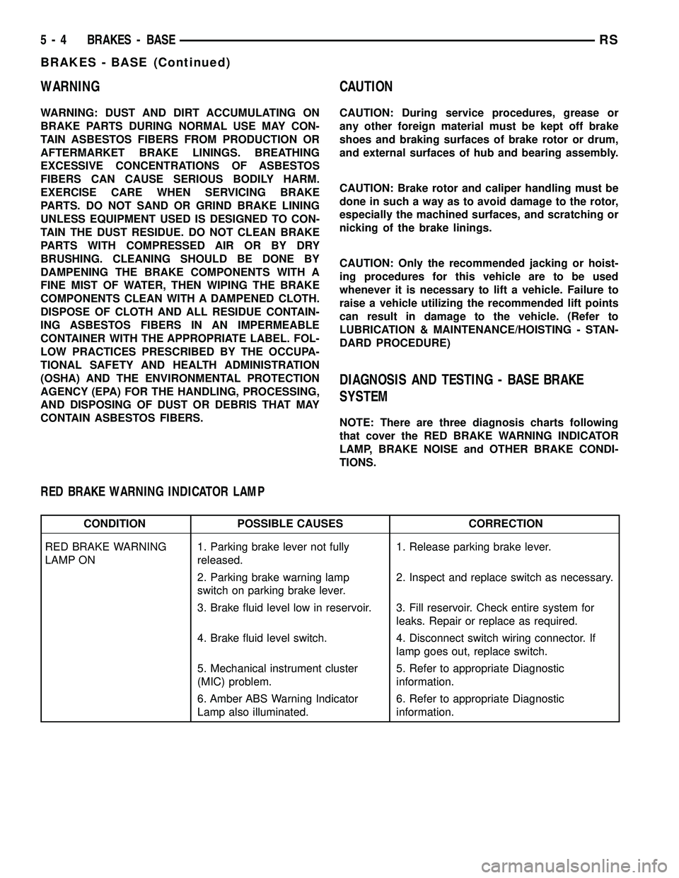
RED BRAKE WARNING INDICATOR LAMP
CONDITION POSSIBLE CAUSES CORRECTION
RED BRAKE WARNING
LAMP ON1. Parking brake lever not fully
released.1. Release parking brake lever.
2. Parking brake warning lamp
switch on parking brake lever.2. Inspect and replace switch as necessary.
3. Brake fluid level low in reservoir. 3. Fill reservoir. Check entire system for
leaks. Repair or replace as required.
4. Brake fluid level switch. 4. Disconnect switch wiring connector. If
lamp goes out, replace switch.
5. Mechanical instrument cluster
(MIC) problem.5. Refer to appropriate Diagnostic
information.
6. Amber ABS Warning Indicator
Lamp also illuminated.6. Refer to appropriate Diagnostic
information.
5 - 4 BRAKES - BASERS
BRAKES - BASE (Continued)
Page 125 of 2339
As disc brake shoe linings wear, master cylinder
reservoir brake fluid level will drop. Adjust as neces-
sary. Fluid level should always be checked after
replacing shoes.
OPERATION - DISC BRAKES (REAR)
The rear disc brakes operate similarly to front disc
brakes, however, there are some features that require
different service procedures.
DIAGNOSIS AND TESTING - DRUM BRAKE
AUTOMATIC ADJUSTER
The rear drum brakes on this vehicle automatically
adjust when required during the normal operation of
the vehicle every time the brakes are applied. Use
the following procedure to test the operation of the
automatic adjuster.
Place the vehicle on a hoist with a helper in the
driver's seat to apply the brakes. Remove the access
plug from the adjustment hole in each brake support
plate to provide visual access of the brake adjuster
star wheel.
To eliminate the condition where maximum adjust-
ment of the rear brake shoes does not allow the auto-
matic adjuster to operate when tested, back the star
wheel off approximately 30 notches. It will be neces-
sary to hold the adjuster lever away from the star
wheel to permit this adjustment.
Have the helper apply the brakes. Upon applica-
tion of the brake pedal, the adjuster lever should
move down, turning the adjuster star wheel. Thus, a
definite rotation of the adjuster star wheel can be
observed if the automatic adjuster is working prop-
erly. If one or more adjusters do not function prop-
erly, the respective drum must be removed for
adjuster servicing.
BRAKE LINES
DESCRIPTION - BRAKE TUBES AND HOSES
The brake tubes are steel with a corrosion-resis-
tant nylon coating applied to the external surfaces.
The flex hoses are made of reinforced rubber with fit-
tings at each end.
The primary and secondary brake tubes leading
from the master cylinder to the ABS ICU Hydraulic
Control Unit (HCU) or the non-ABS junction block
have a special flexible section. This flexible section is
required due to cradle movement while the vehicle is
in motion (The ICU and non-ABS junction block are
mounted to the cradle).If replacement of these
lines is necessary, only the original factory
brake line containing the flexible section must
be used.
OPERATION - BRAKE TUBES AND HOSES
The purpose of the chassis brake tubes and flex
hoses is to transfer the pressurized brake fluid devel-
oped by the master cylinder to the wheel brakes of
the vehicle. The flex hoses are made of rubber to
allow for the movement of the vehicle's suspension.
INSPECTION - BRAKE TUBES AND HOSES
Flexible rubber hose is used at both front brakes
and at the rear axle. Inspection of brake hoses
should be performed whenever the brake system is
serviced and every 7,500 miles or 12 months, which-
ever comes first (every engine oil change). Inspect
hydraulic brake hoses for surface cracking, scuffing,
or worn spots. If the fabric casing of the rubber hose
becomes exposed due to cracks or abrasions in the
rubber hose cover, the hose should be replaced imme-
diately. Eventual deterioration of the hose can take
place with possible burst failure. Faulty installation
can cause twisting, resulting in wheel, tire, or chassis
interference.
The brake tubing should be inspected periodically
for evidence of physical damage or contact with mov-
ing or hot components.
The flexible brake tube sections used on this vehi-
cle in the primary and secondary tubes from the
master cylinder to the ABS hydraulic control unit
connections must also be inspected. This flexible tub-
ing must be inspected for kinks, fraying and contact
with other components or with the body of the vehi-
cle.
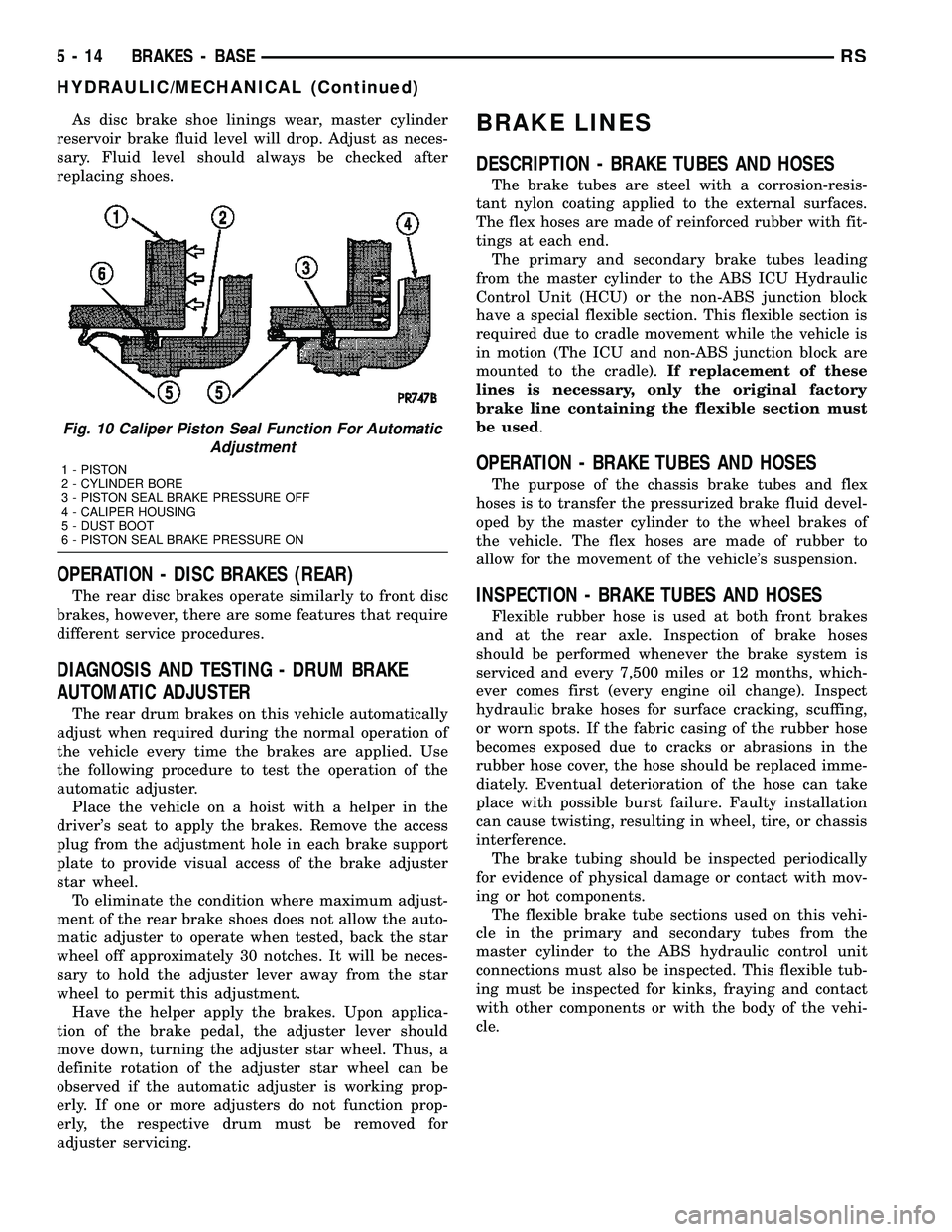
Fig. 10 Caliper Piston Seal Function For Automatic
Adjustment
1 - PISTON
2 - CYLINDER BORE
3 - PISTON SEAL BRAKE PRESSURE OFF
4 - CALIPER HOUSING
5 - DUST BOOT
6 - PISTON SEAL BRAKE PRESSURE ON
5 - 14 BRAKES - BASERS
HYDRAULIC/MECHANICAL (Continued)
Page 233 of 2339
ENGINE
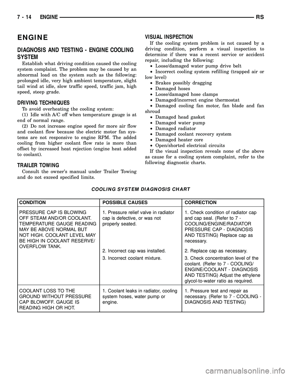
DIAGNOSIS AND TESTING - ENGINE COOLING
SYSTEM
Establish what driving condition caused the cooling
system complaint. The problem may be caused by an
abnormal load on the system such as the following:
prolonged idle, very high ambient temperature, slight
tail wind at idle, slow traffic speed, traffic jam, high
speed, steep grade.
DRIVING TECHNIQUES
To avoid overheating the cooling system:
(1) Idle with A/C off when temperature gauge is at
end of normal range.
(2) Do not increase engine speed for more air flow
and coolant flow because the electric motor fan sys-
tems are not responsive to engine RPM. The added
cooling from higher coolant flow rate is more than
offset by increased heat rejection (engine heat added
to coolant).
TRAILER TOWING
Consult the owner's manual under Trailer Towing
and do not exceed specified limits.
VISUAL INSPECTION
If the cooling system problem is not caused by a
driving condition, perform a visual inspection to
determine if there was a recent service or accident
repair, including the following:
²Loose/damaged water pump drive belt
²Incorrect cooling system refilling (trapped air or
low level)
²Brakes possibly dragging
²Damaged hoses
²Loose/damaged hose clamps
²Damaged/incorrect engine thermostat
²Damaged cooling fan motor, fan blade and fan
shroud
²Damaged head gasket
²Damaged water pump
²Damaged radiator
²Damaged coolant recovery system
²Damaged heater core
²Open/shorted electrical circuits
If the visual inspection reveals none of the above
as cause for a cooling system complaint, refer to the
following diagnostic charts.
COOLING SYSTEM DIAGNOSIS CHART
CONDITION POSSIBLE CAUSES CORRECTION
PRESSURE CAP IS BLOWING
OFF STEAM AND/OR COOLANT.
TEMPERATURE GAUGE READING
MAY BE ABOVE NORMAL BUT
NOT HIGH. COOLANT LEVEL MAY
BE HIGH IN COOLANT RESERVE/
OVERFLOW TANK.1. Pressure relief valve in radiator
cap is defective, or was not
properly seated.1. Check condition of radiator cap
and cap seal. (Refer to 7 -
COOLING/ENGINE/RADIATOR
PRESSURE CAP - DIAGNOSIS
AND TESTING) Replace cap as
necessary.
2. Incorrect cap was installed. 2. Replace cap as necessary.
3. Incorrect coolant mixture. 3. Check concentration level of the
coolant. (Refer to 7 - COOLING/
ENGINE/COOLANT - DIAGNOSIS
AND TESTING) Adjust the ethylene
glycol-to-water ratio as required.
COOLANT LOSS TO THE
GROUND WITHOUT PRESSURE
CAP BLOWOFF. GAUGE IS
READING HIGH OR HOT.1. Coolant leaks in radiator, cooling
system hoses, water pump or
engine.1. Pressure test and repair as
necessary. (Refer to 7 - COOLING -
DIAGNOSIS AND TESTING)
7 - 14 ENGINERS
Page 288 of 2339
The BCM utilizes integrated circuitry and informa-
tion carried on the Programmable Communications
Interface (PCI) data bus network along with many
hard wired inputs to monitor many sensor and
switch inputs throughout the vehicle. In response to
those inputs, the internal circuitry and programming
of the BCM allow it to control and integrate many
electronic functions and features of the vehicle
through both hard wired outputs and the transmis-
sion of electronic message outputs to other electronic
modules in the vehicle over the PCI data bus.
OPERATION
The Body Control Module (BCM) supplies vehicle
occupants with visual and audible information and
controls various vehicle functions. To provide and
receive information, the BCM is interfaced to the
vehicle's serial bus communications network, referred
to as the Programmable Communications Interface
(PCI) bus.
This network consists of the;
²Powertrain Control Module (PCM)
²Transmission Control Module (TCM)
²Mechanical Instrument Cluster (MIC)
²Occupant Restraint Controller (ORC)
²Compass/Mini-Trip Computer (CMTC)
²Electronic Vehicle Information Center (EVIC)
²Controller Antilock Brake (CAB)
²HVAC Control Module
²Sliding Door Control Modules (driver and pas-
senger side doors)
²Power Liftgate Module (PLG)
²Audio system equipped with RAZ, RBU, RBK,
and RBB radios.
²Sentry Key Remote Entry Module (SKREEM).
²Side Impact Airbag Control Module (SIACM)²Memory Seat Module (MSM)
²Sentry Key Immobilizer Module (SKIM)
The BCM is operational when battery power is
supplied to the module.
The BCM provides the following features:
²Power Door Locks
²Automatic Door Locks
²Battery Protection - The BCM will automatically
turn off all exterior lamps after 3 minutes, and all
interior lamps after 15 minutes after the ignition is
turned off, if they are not turned off by the driver.
²Chime Control
²Compass/Mini-Trip support.
²Interior Lighting (Courtesy/Reading Lamps)
²BCM Diagnostic Reporting
²Electronic Liftgate Release (with Power Door
Locks)
²Exterior Lighting
²Headlamp Time Delay (with/without Automatic
Headlamps)
²Illuminated Entry
²Fade to Off Interior Lamps - This feature dims
the interior lighting (courtesy lamps) gradually if the
BCM does not receive any new inputs that would
cause the interior lamps to remain on.
²Pulse Width Modulated Instrument Panel Dim-
ming
²Door Lock Inhibit - This feature disables the
door lock functions if the key is in the ignition and
either front door is ajar. Pressing the Remote Keyless
Entry (RKE) lock/unlock button under these condi-
tions result in normal lock/unlock activation.
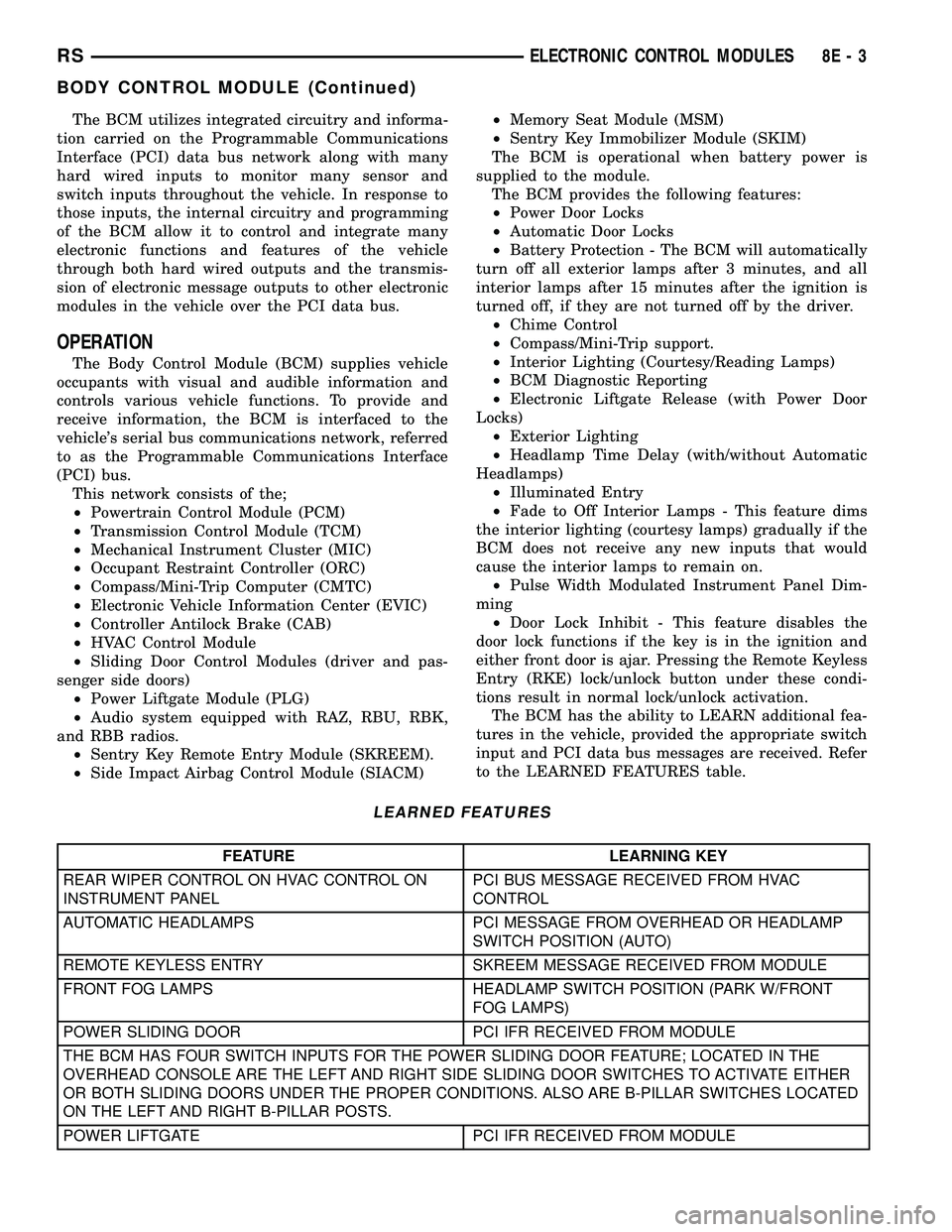
The BCM has the ability to LEARN additional fea-
tures in the vehicle, provided the appropriate switch
input and PCI data bus messages are received. Refer
to the LEARNED FEATURES table.
LEARNED FEATURES
FEATURE LEARNING KEY
REAR WIPER CONTROL ON HVAC CONTROL ON
INSTRUMENT PANELPCI BUS MESSAGE RECEIVED FROM HVAC
CONTROL
AUTOMATIC HEADLAMPS PCI MESSAGE FROM OVERHEAD OR HEADLAMP
SWITCH POSITION (AUTO)
REMOTE KEYLESS ENTRY SKREEM MESSAGE RECEIVED FROM MODULE
FRONT FOG LAMPS HEADLAMP SWITCH POSITION (PARK W/FRONT
FOG LAMPS)
POWER SLIDING DOOR PCI IFR RECEIVED FROM MODULE
THE BCM HAS FOUR SWITCH INPUTS FOR THE POWER SLIDING DOOR FEATURE; LOCATED IN THE
OVERHEAD CONSOLE ARE THE LEFT AND RIGHT SIDE SLIDING DOOR SWITCHES TO ACTIVATE EITHER
OR BOTH SLIDING DOORS UNDER THE PROPER CONDITIONS. ALSO ARE B-PILLAR SWITCHES LOCATED
ON THE LEFT AND RIGHT B-PILLAR POSTS.
POWER LIFTGATE PCI IFR RECEIVED FROM MODULE
RSELECTRONIC CONTROL MODULES8E-3
BODY CONTROL MODULE (Continued)
Page 293 of 2339
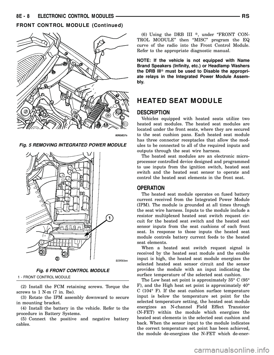
(2) Install the FCM retaining screws. Torque the
screws to 1 N´m (7 in. lbs).
(3) Rotate the IPM assembly downward to secure
in mounting bracket.
(4) Install the battery in the vehicle. Refer to the
procedure in Battery Systems.
(5) Connect the positive and negative battery
cables.(6) Using the DRB IIIt, under ªFRONT CON-
TROL MODULEº then ªMISCº program the EQ
curve of the radio into the Front Control Module.
Refer to the appropriate diagnostic manual.
NOTE: If the vehicle is not equipped with Name
Brand Speakers (Infinity, etc.) or Headlamp Washers
the DRB IIITmust be used to Disable the appropri-
ate relays in the Integrated Power Module Assem-
bly.
HEATED SEAT MODULE
DESCRIPTION
Vehicles equipped with heated seats utilize two
heated seat modules. The heated seat modules are
located under the front seats, where they are secured
to the seat cushion pans. Each heated seat module
has three connector receptacles that allow the mod-
ules to be connected to all of the required inputs and
outputs through the seat wire harness.
The heated seat modules are an electronic micro-
processor controlled device designed and programmed
to use inputs from the ignition switch, heated seat
switch and the heated seat sensor to operate and
control the heated seat elements in the front seat.
OPERATION
The heated seat module operates on fused battery
current received from the Integrated Power Module
(IPM). The module is grounded at all times through
the seat wire harness. Inputs to the module include a
resistor multiplexed heated seat switch request cir-
cuit for the heated seat switch and the heated seat
sensor inputs from the seat cushions of each front
seat. In response to those inputs the heated seat
module controls battery current feeds to the heated
seat elements.
When a heated seat switch request signal is
received by the heated seat module and the enable
input is high, the heated seat module energizes the
selected heated seat sensor circuit and the sensor
provides the module with an input indicating the
surface temperature of the selected seat cushion.
The Low heat set point is approximately 35É C (95É
F), and the High heat set point is approximately 40É
C (104É F). If the seat cushion surface temperature
input is below the temperature set point for the
selected temperature setting, the heated seat module
energizes an N-channel Field Effect Transistor
(N-FET) within the module which energizes the
heated seat elements in the selected seat cushion and
back. When the sensor input to the module indicates
the correct temperature set point has been achieved,
the module de-energizes the N-FET which de-ener-
Fig. 5 REMOVING INTEGRATED POWER MODULE
Fig. 6 FRONT CONTROL MODULE
1 - FRONT CONTROL MODULE
8E - 8 ELECTRONIC CONTROL MODULESRS
FRONT CONTROL MODULE (Continued)
Page 313 of 2339

CONVENTIONAL BATTERY - GASOLINE ENGINE
Low-maintenance batteriesare used on export
vehicles equipped with a gasoline engine, these bat-
teries have removable battery cell caps (Fig. 5).
Watercanbe added to this battery. Under normal
service, the composition of this battery reduces gas-
sing and water loss at normal charge rates. However
these batteries may require additional distilled water
after years of service.
Maintenance-free batteriesare standard facto-
ry-installed equipment on all domestic vehicles. Male
post type terminals made of a soft lead material pro-
trude from the top of the molded plastic battery case
(Fig. 6)to provide the means for connecting the bat-
tery to the vehicle electrical system. The battery pos-
itive terminal post is visibly larger in diameter than
the negative terminal post, for easy identification.
The lettersPOSandNEGare also molded into the
top of the battery case adjacent to their respective
positive and negative terminal posts for additional
identification confirmation.
This battery is designed to provide a safe, efficient
and reliable means of storing electrical energy in a
chemical form. This means of energy storage allows
the battery to produce the electrical energy required
to operate the engine starting system, as well as to
operate many of the other vehicle accessory systems
for limited durations while the engine and/or thecharging system are not operating. The battery is
made up of six individual cells that are connected in
series. Each cell contains positively charged plate
groups that are connected with lead straps to the
positive terminal post, and negatively charged plate
groups that are connected with lead straps to the
negative terminal post. Each plate consists of a stiff
mesh framework or grid coated with lead dioxide
(positive plate) or sponge lead (negative plate). Insu-
lators or plate separators made of a non-conductive
material are inserted between the positive and nega-
tive plates to prevent them from contacting or short-
ing against one another. These dissimilar metal
plates are submerged in a sulfuric acid and water
solution called an electrolyte.
Some factory-installed batteries have a built-in test
indicator (hydrometer). The color visible in the sight
glass of the indicator will reveal the battery condi-
tion. For more information on the use of the built-in
test indicator, refer toStandard Procedures. The
chemical composition of the metal coated plates
within the low-maintenance battery used in export
models reduces battery gassing and water loss at
normal charge and discharge rates. Therefore, the
battery should not require additional water in nor-
mal service. If the electrolyte level in this battery
does become low, distilled water must be added. How-
ever, rapid loss of electrolyte can be caused by an
overcharging condition. Be certain to diagnose the
charging system after replenishing the water in the
Fig. 5 BATTERY CELL CAP REMOVAL/
INSTALLATION - LOW-MAINTANANCE GASOLINE
ENGINE BATTERY - EXPORT
1 - BATTERY CELL CAP
2 - BATTERY CASE
Fig. 6 Maintenance-Free Battery - Domestic
1 - POSITIVE POST
2 - VENT
3 - CELL CAP
4 - VENT
5 - CELL CAP
6 - VENT
7 - NEGATIVE POST
8 - INDICATOR EYE (if equipped)
9 - ELECTROLYTE LEVEL
10 - PLATE GROUPS
11 - MAINTENANCE-FREE BATTERY
8F - 8 BATTERY SYSTEMRS
BATTERY (Continued)
Page 353 of 2339

Hard wired circuitry connects the heated seat sys-
tem components to each other through the electrical
system of the vehicle. These circuits may be con-
nected to each other, to the vehicle electrical system
and to the heated seat system components through
the use of a combination of soldered splices and
splice block connectors. Refer to the appropriate wir-
ing information for complete circuit schematic or con-
nector pin-out information.
OPERATION
The heated seat system components operate on
battery current received through a fuse in the Inte-
grated Power Module (IPM) on a fused ignition
switch output (run) circuit from the Body Control
Module (BCM). The system will only operate when
the ignition switch is in the On position. The heated
seat system will be turned Off automatically when-
ever the ignition switch is turned to any position
except On. Also, the heated seat system will not oper-
ate when the surface temperature of the seat cushion
cover at either heated seat sensor is above the
designed temperature set points of the system.
DIAGNOSIS AND TESTING
HEATED SEAT SYSTEM
The most efficient means of diagnosing the heated
seat system is by individual component. For diagno-
sis of a specific component refer to the following:
²Heated seat module, (Refer to 8 - ELECTRICAL/
ELECTRONIC CONTROL MODULES/MEMORY
HEATED SEAT/MIRROR MODULE - DIAGNOSIS
AND TESTING).
²Heated seat elements, (Refer to 8 - ELECTRI-
CAL/HEATED SEATS/HEATED SEAT ELEMENT -
DIAGNOSIS AND TESTING).
²Heated seat switch, (Refer to 8 - ELECTRICAL/
HEATED SEATS/DRIVER HEATED SEAT SWITCH
- DIAGNOSIS AND TESTING).
²Heated seat sensor, (Refer to 8 - ELECTRICAL/
HEATED SEATS/HEATED SEAT SENSOR - DIAG-
NOSIS AND TESTING).
Refer to the appropriate wiring information for
complete circuit schematic or connector pin-out infor-
mation.
HEATED SEAT SWITCH
DESCRIPTION
The heated seat switches are mounted in the
instrument panel center bezel (Fig. 2). The two three-
position rocker-type switches, one switch for each
front seat, are incorporated into one large switch
assembly that also includes the hazard, rear window
wiper and washer switches. Each heated seat switch
provides a resistor multiplexed signal to its respec-
tive Heated Seat Module (HSM) through separate
hard wired circuits. Each switch has an Off, Low,
and High position so that both the driver and the
front seat passenger can select a preferred seat heat-
ing mode. Each switch has two Light-Emitting
Diodes (LED) which light to indicate that the heater
for the seat is turned on.
The heated seat switches and their LEDs cannot
be repaired. If either switch or LED is faulty or dam-
aged, the entire switch assembly must be replaced.
Fig. 2 HEATED SEAT SWITCH LOCATION
1 - HEATED SEAT SWITCHES
8G - 8 HEATED SEAT SYSTEMRS
HEATED SEAT SYSTEM (Continued)
Page 354 of 2339
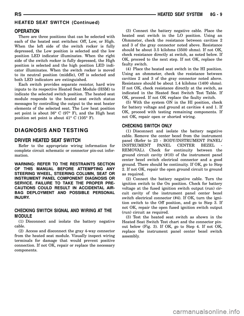
OPERATION
There are three positions that can be selected with
each of the heated seat switches: Off, Low, or High.
When the left side of the switch rocker is fully
depressed, the Low position is selected and the low
position LED indicator illuminates. When the right
side of the switch rocker is fully depressed, the High
position is selected and the high position LED indi-
cator illuminates. When the switch rocker is moved
to its neutral position (middle), Off is selected and
both LED indicators are extinguished.
Each switch provides separate resistor, hard wire
inputs to its respective Heated Seat Module (HSM) to
indicate the selected switch position. The heated seat
module responds to the heated seat switch status
messages by controlling the output to the seat heater
elements of the selected seat. The Low heat position
set point is about 36É C (97É F), and the High heat
position set point is about 41É C (105É F).
DIAGNOSIS AND TESTING
DRIVER HEATED SEAT SWITCH
Refer to the appropriate wiring information for
complete circuit schematic or connector pin-out infor-
mation.
WARNING: REFER TO THE RESTRAINTS SECTION
OF THIS MANUAL BEFORE ATTEMPTING ANY
STEERING WHEEL, STEERING COLUMN, SEAT OR
INSTRUMENT PANEL COMPONENT DIAGNOSIS OR
SERVICE. FAILURE TO TAKE THE PROPER PRE-
CAUTIONS COULD RESULT IN ACCIDENTAL AIR-
BAG DEPLOYMENT AND POSSIBLE PERSONAL
INJURY.
CHECKING SWITCH SIGNAL AND WIRING AT THE
MODULE
(1) Disconnect and isolate the battery negative
cable.
(2) Access and disconnect the gray 4-way connector
from the heated seat module. Visually inspect wiring
terminals for damage that would prevent positive
connection. If not OK, repair or replace the necessary
components.(3) Connect the battery negative cable. Place the
heated seat switch in the LO position. Using an
Ohmmeter, check the resistance between cavities 2
and 3 of the gray connector noted above. Resistance
should be about 3.5 kilohms (3500 ohms). If not OK,
check resistance directly at switch, as noted below. If
OK, proceed to the next step. If not OK, replace the
faulty switch.
(4) Place the heated seat switch in the HI position.
Using an ohmmeter, check the resistance between
cavities 2 and 3 of the gray connector noted above.
Resistance should be about 1.4 kilohms (1400 ohms).
If not OK, check resistance directly at the switch, as
indicated in the Heated Seat Switch Test Table. If
OK, proceed. If not OK replace the faulty switch.
(5) With the system ON in the HI position, check
for battery voltage and ground at cavities 4 and 1. If
OK, proceed with testing remaining components. If
not OK, repair open or shorted wiring.
CHECKING SWITCH ONLY
(1) Disconnect and isolate the battery negative
cable. Remove the center bezel from the instrument
panel (Refer to 23 - BODY/INSTRUMENT PANEL/
INSTRUMENT PANEL CENTER BEZEL -
REMOVAL). Check for continuity between the
ground circuit cavity (#10) of the instrument panel
center bezel switch electrical connector and a good
ground. There should be continuity. If OK, go to Step
2. If not OK, repair the open ground circuit to ground
as required.
(2) Connect the battery negative cable. Turn the
ignition switch to the On position. Check for battery
voltage at the fused ignition switch output (run) cir-
cuit cavity of the instrument panel center bezel
switch electrical connector (#4). If OK, turn the igni-
tion switch to the Off position, and go to Step 3. If
not OK, repair the open fused ignition switch output
(run) circuit as required.
(3) Test the heated seat switch as shown in the
Heated Seat Switch Test chart and the connector pin-
out below (Fig. 3). If OK, go to Step 4. If not OK,
replace the instrument panel center bezel switch
assembly.
RSHEATED SEAT SYSTEM8G-9
HEATED SEAT SWITCH (Continued)