Page 61 CHRYSLER VOYAGER 2005 User Guide
[x] Cancel search | Manufacturer: CHRYSLER, Model Year: 2005, Model line: VOYAGER, Model: CHRYSLER VOYAGER 2005Pages: 2339, PDF Size: 59.69 MB
Page 212 of 2339
For more information, (Refer to 5 - BRAKES/HY-
DRAULIC/MECHANICAL/ICU (INTEGRATED CON-
TROL UNIT) - DESCRIPTION)
OPERATION
For information on the operation of the HCU as a
whole, refer to Hydraulic Circuits And Valve Opera-
tion which can be found elsewhere in this section.
For information on the operation of the components
within the HCU, refer to the following three topics.
VALVES AND SOLENOIDS
The valve block contains four inlet valves and four
outlet valves. The inlet valves are spring-loaded in
the open position and the outlet valves are spring-
loaded in the closed position during normal braking.
The fluid is allowed to flow from the master cylinder
to the wheel brakes.
During an ABS stop, these valves cycle to maintain
the proper slip ratio for each wheel. The inlet valve
closes preventing further pressure increase and the
outlet valve opens to provide a path from the wheel
brake to the HCU accumulators and pump/motor.
This releases (decays) pressure from the wheel brake,
thus releasing the wheel from excessive slippage.
Once the wheel is no longer slipping, the outlet valve
is closed and the inlet valve is opened to reapply
(build) pressure.
On vehicles with traction control, there is an extra
set of valves and solenoids. The ASR valves, mounted
in the HCU valve block, are normally in the open
position and close only when the traction control is
applied.
These isolator valves are used to isolate the rear
(non-driving) wheels of the vehicle from the hydraulic
pressure that the HCU pump/motor is sending to the
front (driving) wheels when traction control is being
applied. The rear brakes need to be isolated from the
master cylinder when traction control is being
applied so the rear wheels do not drag. For more
information, refer to Traction Control System in this
section.
BRAKE FLUID ACCUMULATORS
There are two fluid accumulators in the HCU±one
for the primary hydraulic circuit and one for the sec-
ondary hydraulic circuit. Each hydraulic circuit uses
a 5 cc accumulator.
The fluid accumulators temporarily store brake
fluid that is removed from the wheel brakes during
an ABS cycle. This stored fluid is used by the pump/
motor to provide build pressure for the brake hydrau-
lic system. When the antilock stop is complete, the
accumulators are drained by the pump/motor.
On ABS-only vehicles, there is a mini-accumulator
on the secondary hydraulic circuit that protects the
master cylinder seals during an ABS stop, and there
is a noise dampening chamber on the primary circuit.
On ABS with traction control vehicles, there are
two noise dampening chambers in the HCU.
PUMP/MOTOR
There are two pump assemblies in the HCUÐone
for the primary hydraulic circuit and one for the sec-
ondary hydraulic circuit. Both pumps are driven by a
common electric motor. This DC-type motor is inte-
gral to the HCU and is controlled by the CAB.
The pump/motor provides the extra amount of
brake fluid needed during antilock braking. Brake
fluid is released to the accumulators when the outlet
valve is opened during an antilock stop. The pump
mechanism consists of two opposing pistons operated
by an eccentric camshaft. In operation, one piston
draws fluid from the accumulators, and the opposing
piston pumps fluid to the master cylinder circuits.
When the antilock stop is complete, the pump/motor
drains the accumulators.
The CAB may turn on the pump/motor when an
antilock stop is detected. The pump/motor continues
to run during the antilock stop and is turned off after
the stop is complete. Under some conditions, the
pump/motor runs to drain the accumulators during
the next drive-off.
The pump/motor is not a serviceable item; if it
requires replacement, the HCU must be replaced.
RSBRAKES - ABS5 - 101
HCU (HYDRAULIC CONTROL UNIT) (Continued)
Page 220 of 2339
COOLING
TABLE OF CONTENTS
page page
COOLING
DESCRIPTION
DESCRIPTION - COOLING SYSTEM........1
DESCRIPTION - HOSE CLAMPS...........1
OPERATION
OPERATION - COOLING SYSTEM.........2
OPERATION - HOSE CLAMPS............2
DIAGNOSIS AND TESTING
DIAGNOSIS AND TESTING - COOLING
SYSTEM LEAK TEST....................2
DIAGNOSIS AND TESTING - COOLING
SYSTEM FLOW CHECK.................3
DIAGNOSIS AND TESTING - COOLING
SYSTEM AERATION....................4
DIAGNOSIS AND TESTING - COOLING
SYSTEM DEAERATION..................4
STANDARD PROCEDURE
STANDARD PROCEDURE - COOLING
SYSTEM DRAINING....................4STANDARD PROCEDURE - COOLING
SYSTEM FILLING......................4
STANDARD PROCEDURE - ADDING
ADDITIONAL COOLANT.................4
STANDARD PROCEDURE - COOLANT
LEVEL CHECK........................4
SPECIFICATIONS
ACCESSORY DRIVE BELT TENSION.......5
TORQUE.............................5
SPECIAL TOOLS
COOLING SYSTEM.....................6
ACCESSORY DRIVE.......................7
ENGINE...............................13
TRANSMISSION.........................38
COOLING
DESCRIPTION
DESCRIPTION - COOLING SYSTEM
The cooling system components consist of a radia-
tor, electric fan motors, shroud, pressure cap, thermo-
stat, transmission oil cooler, water pump, hoses,
clamps, coolant, and a coolant reserve system to com-
plete the circuit.
DESCRIPTION - HOSE CLAMPS
The cooling system uses spring type hose clamps.
If a spring type clamp replacement is necessary,
replace with the original Mopartequipment spring
type clamp.
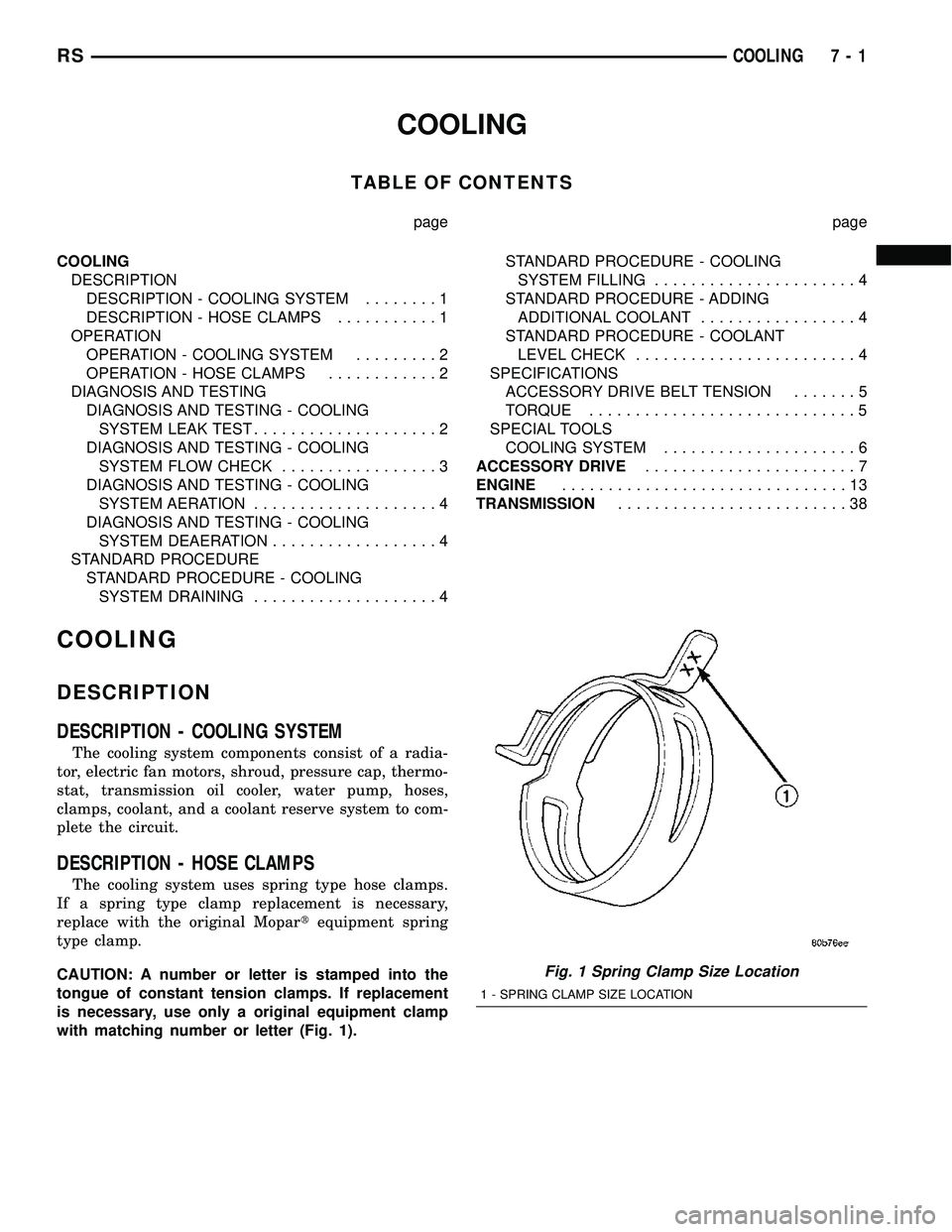
CAUTION: A number or letter is stamped into the
tongue of constant tension clamps. If replacement
is necessary, use only a original equipment clamp
with matching number or letter (Fig. 1).
Fig. 1 Spring Clamp Size Location
1 - SPRING CLAMP SIZE LOCATION
RSCOOLING7-1
Page 226 of 2339
ACCESSORY DRIVE
TABLE OF CONTENTS
page page
DRIVE BELTS
DIAGNOSIS AND TESTING - ACCESSORY
DRIVE BELT..........................7
CLEANING.............................8
INSPECTION...........................8
DRIVE BELTS - 2.4L
STANDARD PROCEDURE - CHECKING
POWER STEERING BELT TENSION........8
REMOVAL.............................9
INSTALLATION..........................9ADJUSTMENTS........................10
BELT TENSIONER - 2.4L
REMOVAL.............................11
INSTALLATION.........................11
DRIVE BELTS - 3.3/3.8L
REMOVAL.............................11
INSTALLATION.........................12
BELT TENSIONER - 3.3/3.8L
REMOVAL.............................12
INSTALLATION.........................12
DRIVE BELTS
DIAGNOSIS AND TESTING - ACCESSORY DRIVE BELT
CONDITION POSSIBLE CAUSES CORRECTIONS
INSUFFICIENT ACCESSORY
OUTPUT DUE TO BELT SLIPPAGE1. Belt too loose 1. (a) Replace belt (auto-tensioned
belts)
(b) Adjust power steering belt
tension (4 cyl. engine)
2. Belt excessively glazed or worn 2. Replace and tighten as specified
BELT SQUEAL WHEN
ACCELERATING ENGINE1. Belts too loose 1. (a) Replace belt (auto-tensioned
belts)
(b) Adjust power steering belt
tension (4 cyl. engine)
2. Belt glazed 2. Replace belts
BELT SQUEAK AT IDLE 1. Belts too loose 1. (a) Replace belt (auto-tensioned
belts)
(b) Adjust power steering belt
tension (4 cyl. engine)
2. Dirt or paint imbedded in belt 2. Replace belt
3. Non-uniform belt 3. Replace belt
4. Misaligned pulleys 4. Align accessories
5. Non-uniform groove or eccentric
pulley5. Replace pulley
RSACCESSORY DRIVE7-7
Page 232 of 2339
ENGINE
TABLE OF CONTENTS
page page
ENGINE
DIAGNOSIS AND TESTING - ENGINE
COOLING SYSTEM....................14
CLEANING............................18
INSPECTION..........................18
COOLANT
DESCRIPTION - ENGINE COOLANT.........19
DIAGNOSIS AND TESTING - COOLANT
CONCENTRATION TESTING.............19
STANDARD PROCEDURE - COOLANT
SERVICE............................19
COOLANT RECOVERY CONTAINER
DESCRIPTION.........................20
OPERATION...........................20
DIAGNOSIS AND TESTING - COOLANT
RECOVERY SYSTEM..................20
REMOVAL.............................20
INSTALLATION.........................20
ENGINE BLOCK HEATER
DESCRIPTION.........................20
OPERATION...........................20
DIAGNOSIS AND TESTING - ENGINE BLOCK
HEATER TESTING.....................21
REMOVAL.............................21
INSTALLATION.........................21
ENGINE COOLANT TEMPERATURE SENSOR -
2.4L
DESCRIPTION.........................21
REMOVAL.............................21
INSTALLATION.........................21
ENGINE COOLANT TEMPERATURE SENSOR -
3.3/3.8L
DESCRIPTION.........................21
REMOVAL.............................21
INSTALLATION.........................23
ENGINE COOLANT THERMOSTAT
DESCRIPTION.........................23
OPERATION...........................23
DIAGNOSIS AND TESTING - ENGINE
COOLANT THERMOSTAT...............23
ENGINE COOLANT THERMOSTAT - 2.4L
REMOVAL.............................24
INSTALLATION.........................24
ENGINE COOLANT THERMOSTAT - 3.3/3.8L
REMOVAL.............................24
INSTALLATION.........................25
RADIATOR
REMOVAL.............................26INSTALLATION.........................27
RADIATOR DRAINCOCK
REMOVAL.............................27
INSTALLATION.........................27
RADIATOR PRESSURE CAP
DESCRIPTION.........................27
OPERATION...........................27
DIAGNOSIS AND TESTING
DIAGNOSIS AND TESTING - COOLING
SYSTEM PRESSURE CAP TESTING.......28
DIAGNOSIS AND TESTING - RADIATOR
CAP TO FILLER NECK SEAL.............28
CLEANING............................28
INSPECTION..........................29
RADIATOR FAN
DESCRIPTION.........................29
OPERATION...........................29
DIAGNOSIS AND TESTING - RADIATOR FAN
MOTOR .............................30
REMOVAL.............................30
INSTALLATION.........................30
RADIATOR FAN RELAY
DESCRIPTION.........................31
OPERATION...........................31
REMOVAL.............................31
INSTALLATION.........................31
WATER PUMP - 2.4L
DESCRIPTION.........................32
REMOVAL.............................32
CLEANING............................32
INSPECTION..........................32
INSTALLATION.........................32
WATER PUMP - 3.3/3.8L
DESCRIPTION.........................34
REMOVAL.............................34
CLEANING............................35
INSPECTION..........................35
INSTALLATION.........................35
WATER PUMP INLET TUBE - 2.4L
DESCRIPTION.........................36
REMOVAL.............................36
INSTALLATION.........................36
WATER PUMP INLET TUBE - 3.3/3.8L
REMOVAL.............................37
INSTALLATION.........................37
RSENGINE7-13
Page 254 of 2339
(8) Remove and discard the seal.
(9) Clean seal groove and sealing surfaces on
pump and timing chain case cover. Take care not to
scratch or gouge sealing surfaces.
CLEANING
Clean gasket mating surfaces as necessary.
INSPECTION
Replace the water pump if it has any of the follow-
ing defects.
(1) Damage or cracks on the pump body.
(2) Coolant leaks; this will be evident by a wet
stream of coolant running down the pump body and
components below. A thin stain below the weep hole
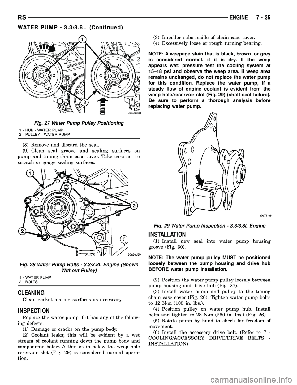
reservoir slot (Fig. 29) is considered normal opera-
tion.(3) Impeller rubs inside of chain case cover.
(4) Excessively loose or rough turning bearing.
NOTE: A weepage stain that is black, brown, or grey
is considered normal, if it is dry. If the weep
appears wet; pressure test the cooling system at
15±18 psi and observe the weep area. If weep area
remains unchanged, do not replace the water pump
for this condition. Replace the water pump, if a
steady flow of engine coolant is evident from the
weep hole/reservoir slot (Fig. 29) (shaft seal failure).
Be sure to perform a thorough analysis before
replacing water pump.
INSTALLATION
(1) Install new seal into water pump housing
groove (Fig. 30).
NOTE: The water pump pulley MUST be positioned
loosely between the pump housing and drive hub
BEFORE water pump installation.
(2) Position the water pump pulley loosely between
pump housing and drive hub (Fig. 27).
(3) Install water pump and pulley to the timing
chain case cover (Fig. 26). Tighten water pump bolts
to 12 N´m (105 in. lbs.).
(4) Position pulley on water pump hub. Install
bolts and tighten to 28 N´m (250 in. lbs.) (Fig. 26).
(5) Rotate pump by hand to check for freedom of
movement.
(6) Install the accessory drive belt. (Refer to 7 -
COOLING/ACCESSORY DRIVE/DRIVE BELTS -
INSTALLATION)
Fig. 27 Water Pump Pulley Positioning
1 - HUB - WATER PUMP
2 - PULLEY - WATER PUMP
Fig. 28 Water Pump Bolts - 3.3/3.8L Engine (Shown
Without Pulley)
1 - WATER PUMP
2 - BOLTS
Fig. 29 Water Pump Inspection - 3.3/3.8L Engine
RSENGINE7-35
WATER PUMP - 3.3/3.8L (Continued)
Page 257 of 2339
TRANSMISSION
TABLE OF CONTENTS
page page
TRANSMISSION
STANDARD PROCEDURE - TRANSMISSION
COOLER LINE QUICK CONNECT FITTING
DISASSEMBLY/ASSEMBLY..............38
TRANSMISSION OIL COOLER
DESCRIPTION.........................39INSPECTION..........................39
TRANSMISSION OIL COOLER LINES
REMOVAL.............................39
INSTALLATION.........................40
TRANSMISSION
STANDARD PROCEDURE - TRANSMISSION
COOLER LINE QUICK CONNECT FITTING
DISASSEMBLY/ASSEMBLY
DISCONNECT
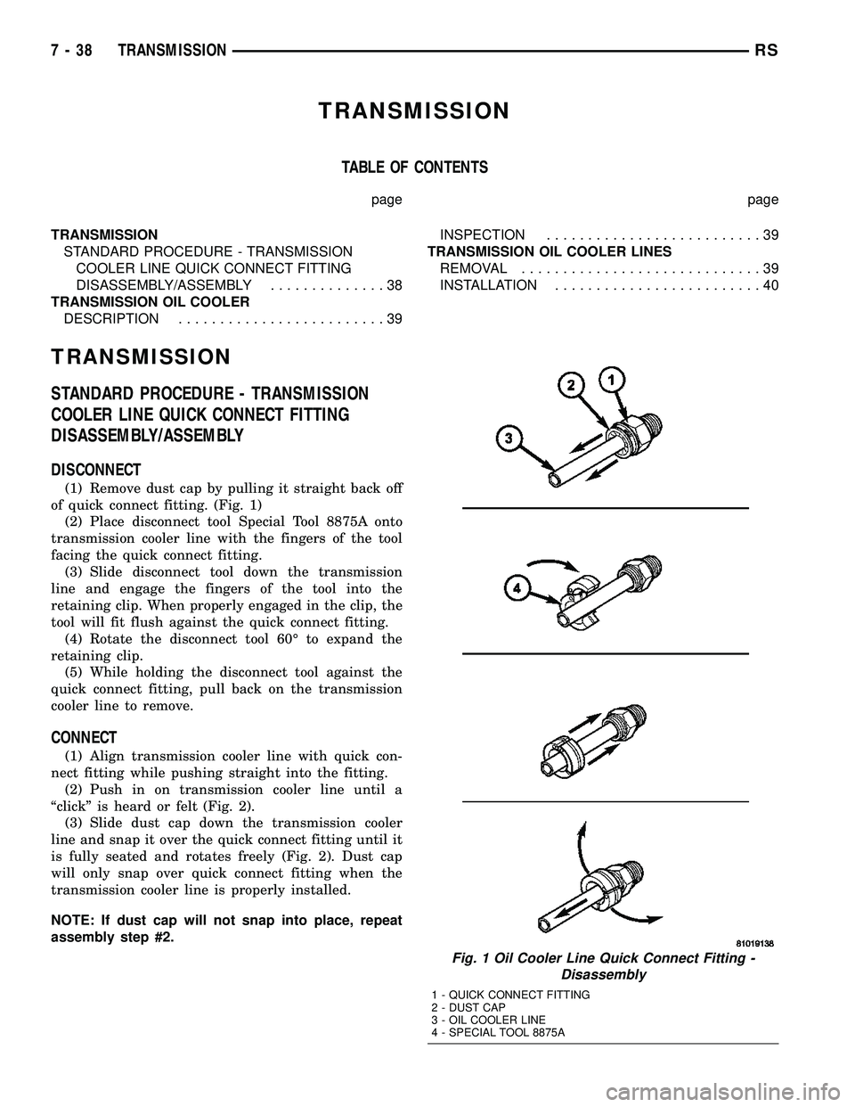
(1) Remove dust cap by pulling it straight back off
of quick connect fitting. (Fig. 1)
(2) Place disconnect tool Special Tool 8875A onto
transmission cooler line with the fingers of the tool
facing the quick connect fitting.
(3) Slide disconnect tool down the transmission
line and engage the fingers of the tool into the
retaining clip. When properly engaged in the clip, the
tool will fit flush against the quick connect fitting.
(4) Rotate the disconnect tool 60É to expand the
retaining clip.
(5) While holding the disconnect tool against the
quick connect fitting, pull back on the transmission
cooler line to remove.
CONNECT
(1) Align transmission cooler line with quick con-
nect fitting while pushing straight into the fitting.
(2) Push in on transmission cooler line until a
ªclickº is heard or felt (Fig. 2).
(3) Slide dust cap down the transmission cooler
line and snap it over the quick connect fitting until it
is fully seated and rotates freely (Fig. 2). Dust cap
will only snap over quick connect fitting when the
transmission cooler line is properly installed.
NOTE: If dust cap will not snap into place, repeat
assembly step #2.
Fig. 1 Oil Cooler Line Quick Connect Fitting -
Disassembly
1 - QUICK CONNECT FITTING
2 - DUST CAP
3 - OIL COOLER LINE
4 - SPECIAL TOOL 8875A
7 - 38 TRANSMISSIONRS
Page 260 of 2339
AUDIO/VIDEO
TABLE OF CONTENTS
page page
AUDIO/VIDEO
DESCRIPTION..........................1
DIAGNOSIS AND TESTING
AUDIO/VIDEO.........................2
AMPLIFIER
REMOVAL.............................7
INSTALLATION..........................7
ANTENNA BODY AND CABLE
DESCRIPTION..........................7
OPERATION............................7
DIAGNOSIS AND TESTING
ANTENNA BODY AND CABLE.............8
REMOVAL.............................8
INSTALLATION..........................8
ANTENNA MODULE - EXPORT
DESCRIPTION.........................10
OPERATION...........................10
DIAGNOSIS AND TESTING
ANTENNA MODULE - EXPORT...........10
REMOVAL.............................10
INSTALLATION.........................10
ANTENNA - NAVIGATION RADIO
REMOVAL.............................11
INSTALLATION.........................11
CD CHANGER
DESCRIPTION.........................11
OPERATION...........................11
REMOVAL.............................11
INSTALLATION.........................11
DVD PLAYER
DESCRIPTION.........................12
REMOVAL.............................12
INSTALLATION.........................12
INSTRUMENT PANEL ANTENNA CABLE
REMOVAL.............................12INSTALLATION.........................12
QUARTER GLASS INTEGRAL ANTENNA -
EXPORT
DESCRIPTION.........................13
OPERATION...........................13
DIAGNOSIS AND TESTING
QUARTER GLASS INTEGRAL ANTENNA -
EXPORT............................13
RADIO
DESCRIPTION.........................13
OPERATION...........................14
DIAGNOSIS AND TESTING
RADIO..............................14
REMOVAL.............................14
INSTALLATION.........................15
RADIO NOISE SUPPRESSION COMPONENTS
DESCRIPTION.........................15
OPERATION...........................15
REMOTE SWITCHES
DESCRIPTION.........................16
OPERATION...........................16
DIAGNOSIS AND TESTING
REMOTE SWITCHES..................16
REMOVAL.............................17
INSTALLATION.........................17
SPEAKER
DIAGNOSIS AND TESTING
SPEAKER...........................18
REMOVAL.............................18
INSTALLATION.........................19
VIDEO SCREEN
DESCRIPTION.........................20
OPERATION...........................20
REMOVAL.............................20
INSTALLATION.........................20
AUDIO/VIDEO
DESCRIPTION
An audio system is standard on this model. A rear
seat video system is an available option. Several com-
binations of radio receivers are offered on this model.
The audio/video system uses an ignition switched
source of battery current so that the system will only
operate when the ignition switch is in the RUN or
ACCESSORY/ACCESSORY DELAY positions.
The audio system includes the following compo-
nents:²Amplifier
²Antenna
²CD changer (if equipped)
²DVD player (if equipped)
²Radio noise suppression components
²Radio receiver
²Speakers
²Video screen (if equipped)
Certain functions and features of the audio/video
system rely upon resources shared with other elec-
tronic modules in the vehicle over the Programmable
Communication Interface (PCI) bus network. The
data bus network allows the sharing of sensor infor-
RSAUDIO/VIDEO8A-1
Page 280 of 2339
CHIME/BUZZER
TABLE OF CONTENTS
page page
CHIME/BUZZER
DESCRIPTION..........................1
OPERATION............................1
WARNING.............................2
DIAGNOSIS AND TESTING - CHIME SYSTEM . . 2
PARK ASSIST DISPLAY
DESCRIPTION..........................3
OPERATION............................3
REMOVAL.............................4
INSTALLATION..........................4PARK ASSIST MODULE
DESCRIPTION..........................4
OPERATION............................5
REMOVAL.............................5
INSTALLATION..........................6
PARK ASSIST SENSOR
DESCRIPTION..........................6
OPERATION............................6
REMOVAL.............................6
INSTALLATION..........................6
CHIME/BUZZER
DESCRIPTION
The chime/buzzer system provides the driver with
warning chimes for:
²Seat Belt
²Exterior Lamps ON
²Key-In Ignition
²Engine Temperature Critical
²Turn Signals ON
²Dome Lamp ON
²Low Oil Pressure
²High Speed Warning
²Warning Lamp Announcement
²Key-In Accessory
²Low/High Tire Pressure
²Service Tire Pressure Monitor (TPM)
HIGH SPEED WARNING - EXPORT
The chime will sound, acting as a warning to the
driver that the vehicle speed has exceeded 120 3
Kp/h (75 2 mph).
Refer to the proper body diagnostic information
diagnosis and testing with a scan tool.
PARK ASSIST SYSTEM
The Park Assist System is an electronic parking
aid that alerts the driver to obstacles which are
located immediately behind the vehicle. Objects are
sensed using ultrasonic sound waves. When an object
is detected, the system will give the driver visual and
audible warnings. The system is customer program-
mable through the Electronic Vehicle Information
Center (EVIC) but will be enabled from the factory
as a default.
The major components of the park assist system
are:²Park Assist Module- supplies voltage to the
object detection sensors and park assist display. It
triggers the sensors, analyzes the echo delay times
and calculates obstacle distances. It sends display
information to the park assist display, performs sys-
tem diagnostics, and communicates via the Program-
mable Communication Interface (PCI) date bus
network.
²Park Assist Sensors- there are four sensors
located in the rear bumper that generate ultrasonic
pulses when triggered by the park assist module. The
sensors signal the park assist module when reflected
ultrasonic pulses are received.
²Park Assist Display- there are sixteen Light
Emitting Diode (LED) indicators which provide indi-
cation of relative distance to obstacles. When the sys-
tem is engaged and no obstacles are detected, the
two outermost yellow LED's are lit at reduced bright-
ness to show the system is working. As the distance
to a detected obstacle decreases, more yellow LED's
towards the center of the display illuminate.
For diagnosis and testing of the park assist sys-
tem, use a scan tool and the appropriate body diag-
nostic information.
OPERATION
Refer to the proper Body Diagnostic Procedures
manual for complete chime/buzzer operation and con-
ditions for operation.
HIGH SPEED WARNING - EXPORT
When the vehicle speed sensor sees 120 3 Km/h
(75 2 mph), it sends a PCI data bus message to the
Body Control Module (BCM). The BCM then turns on
the chime to let the driver know that the vehicle has
reached a speed greater than 120 3 Km/h (75 2
mph). This audible message will continue until the
vehicle is slowed below the predetermined speed.
RSCHIME/BUZZER8B-1
Page 286 of 2339
ELECTRONIC CONTROL MODULES
TABLE OF CONTENTS
page page
ELECTRONIC CONTROL MODULES
STANDARD PROCEDURE - PCM/SKIM
PROGRAMMING.......................1
BODY CONTROL MODULE
DESCRIPTION..........................2
OPERATION............................3
REMOVAL.............................4
INSTALLATION..........................4
CONTROLLER ANTILOCK BRAKE
DESCRIPTION..........................4
OPERATION............................5
REMOVAL.............................5
INSTALLATION..........................6
DATA LINK CONNECTOR
DESCRIPTION..........................6
OPERATION............................6
FRONT CONTROL MODULE
DESCRIPTION..........................7
OPERATION............................7
DIAGNOSIS AND TESTING
FRONT CONTROL MODULE..............7
REMOVAL.............................7
INSTALLATION..........................7
HEATED SEAT MODULE
DESCRIPTION..........................8
OPERATION............................8
DIAGNOSIS AND TESTING
HEATED SEAT MODULE.................9
REMOVAL.............................9
INSTALLATION..........................9
MEMORY SEAT/MIRROR MODULE
DESCRIPTION..........................9
OPERATION............................9
DIAGNOSIS AND TESTING
MEMORY SEAT/MIRROR MODULE.........9
REMOVAL.............................10
INSTALLATION.........................10
POWER LIFTGATE CONTROL MODULE
DESCRIPTION.........................10OPERATION...........................10
DIAGNOSIS AND TESTING
POWER LIFTGATE CONTROL MODULE....10
REMOVAL.............................10
INSTALLATION.........................11
POWERTRAIN CONTROL MODULE
DESCRIPTION
DESCRIPTION........................11
OPERATION - SENSOR RETURN - PCM
INPUT..............................14
OPERATION - DATA BUS COMMUNICATION
RECEIVE - PCM INPUT.................14
OPERATION - IGNITION SENSE - PCM
INPUT..............................14
OPERATION - PCM GROUND............14
OPERATION - 5 VOLT SUPPLY - PCM
OUTPUT............................15
STANDARD PROCEDURE
STANDARD PROCEDURE - OBTAINING
DIAGNOSTIC TROUBLE CODES..........15
STANDARD PROCEDURE - PINION
FACTOR SETTING.....................15
STANDARD PROCEDURE - QUICK LEARN
PROCEDURE........................15
REMOVAL
REMOVAL - SBEC CONTROLLER.........16
REMOVAL - NGC CONTROLLER..........16
INSTALLATION
INSTALLATION - SBEC CONTROLLER.....17
INSTALLATION.......................17
SLIDING DOOR CONTROL MODULE
DESCRIPTION.........................18
OPERATION...........................18
DIAGNOSIS AND TESTING
SLIDING DOOR CONTROL MODULE......18
REMOVAL.............................18
INSTALLATION.........................19
ELECTRONIC CONTROL
MODULES
STANDARD PROCEDURE - PCM/SKIM
PROGRAMMING
NOTE: Before replacing the PCM for a failed driver,
control circuit or ground circuit, be sure to checkthe related component/circuit integrity for failures
not detected due to a double fault in the circuit.
Most PCM driver/control circuit failures are caused
by internal component failures (i.e. relay and sole-
noids) and shorted circuits (i.e. pull-ups, drivers
and switched circuits). These failures are difficult to
detect when a double fault has occurred and only
one DTC has set.
RSELECTRONIC CONTROL MODULES8E-1
Page 287 of 2339
When a PCM (SBEC) and the SKIM are replaced
at the same time perform the following steps in
order:
(1) Program the new PCM (SBEC)
(2) Program the new SKIM
(3) Replace all ignition keys and program them to
the new SKIM.
PROGRAMMING THE PCM (SBEC)
The SKIS Secret Key is an ID code that is unique
to each SKIM. This code is programmed and stored
in the SKIM, PCM and transponder chip (ignition
keys). When replacing the PCM it is necessary to
program the secret key into the new PCM using the
DRB III. Perform the following steps to program the
secret key into the PCM.
(1) Turn the ignition switch on (transmission in
park/neutral).
(2) Use the DRB III and select THEFT ALARM,
SKIM then MISCELLANEOUS.
(3) Select PCM REPLACED (GAS ENGINE).
(4) Enter secured access mode by entering the
vehicle four-digit PIN.
(5) Select ENTER to update PCM VIN.
NOTE: If three attempts are made to enter secure
access mode using an incorrect PIN, secured
access mode will be locked out for one hour. To
exit this lockout mode, turn the ignition to the RUN
position for one hour then enter the correct PIN.
(Ensure all accessories are turned off. Also monitor
the battery state and connect a battery charger if
necessary).
(6) Press ENTER to transfer the secret key (the
SKIM will send the secret key to the PCM).
(7) Press Page Back to get to the Select System
menu and select ENGINE, MISCELLANEOUS, and
SRI MEMORY CHECK.
(8) The DRB III will ask, Is odometer reading
between XX and XX? Select the YES or NO button on
the DRB III. If NO is selected, the DRB III will read,
Enter odometer Reading
the odometer reading from the Instrument Panel and
press ENTER.
PROGRAMMING THE SKIM
(1) Turn the ignition switch on (transmission in
park/neutral).
(2) Use the DRB III and select THEFT ALARM,
SKIM then MISCELLANEOUS.
(3) Select PCM REPLACED (GAS ENGINE).
(4) Program the vehicle four-digit PIN into SKIM.
(5) Select COUNTRY CODE and enter the correct
country.NOTE: Be sure to enter the correct country code. If
the incorrect country code is programmed into
SKIM, the SKIM must be replaced.
(6) Select YES to update VIN (the SKIM will learn
the VIN from the PCM).
(7) Press ENTER to transfer the secret key (the
PCM will send the secret key to the SKIM).
(8) Program ignition keys to SKIM.
NOTE: If the PCM and the SKIM are replaced at the
same time, all vehicle keys will need to be replaced
and programmed to the new SKIM.
PROGRAMMING IGNITION KEYS TO THE SKIM
(1) Turn the ignition switch on (transmission in
park/neutral).
(2) Use the DRB III and select THEFT ALARM,
SKIM then MISCELLANEOUS.
(3) Select PROGRAM IGNITION KEY'S.
(4) Enter secured access mode by entering the
vehicle four-digit PIN.
NOTE: A maximum of eight keys can be learned to
each SKIM. Once a key is learned to a SKIM it (the
key) cannot be transferred to another vehicle.
If ignition key programming is unsuccessful, the
DRB III will display one of the following messages:
Programming Not Attempted - The DRB III
attempts to read the programmed key status and
there are no keys programmed into SKIM memory.
Programming Key Failed (Possible Used Key From
Wrong Vehicle) - SKIM is unable to program key due
to one of the following:
²faulty ignition key transponder
²ignition key is programmed to another vehicle.
8 Keys Already Learned, Programming Not Done -
SKIM transponder ID memory is full.
(5) Obtain ignition keys to be programmed from
customer (8 keys maximum).
(6) Using the DRB III, erase all ignition keys by
selecting MISCELLANEOUS and ERASE ALL CUR-
RENT IGN. KEYS.
(7) Program all ignition keys.
Learned Key In Ignition - Ignition key transponder
ID is currently programmed in SKIM memory.
BODY CONTROL MODULE
DESCRIPTION
The Body Control Module (BCM) is located in the
passenger compartment, attached to the bulkhead
underneath the left side of the instrument panel.
8E - 2 ELECTRONIC CONTROL MODULESRS
ELECTRONIC CONTROL MODULES (Continued)