accumulator CHRYSLER VOYAGER 2005 User Guide
[x] Cancel search | Manufacturer: CHRYSLER, Model Year: 2005, Model line: VOYAGER, Model: CHRYSLER VOYAGER 2005Pages: 2339, PDF Size: 59.69 MB
Page 1463 of 2339

SPEED SENSOR - INPUT
DESCRIPTION........................120
OPERATION..........................120
REMOVAL............................121
INSTALLATION........................121
SPEED SENSOR - OUTPUT
DESCRIPTION........................122
OPERATION..........................122
REMOVAL............................123
INSTALLATION........................123
TORQUE CONVERTER
DESCRIPTION........................124
OPERATION..........................128
REMOVAL............................129
INSTALLATION........................129TRANSMISSION CONTROL RELAY
DESCRIPTION........................130
OPERATION..........................130
TRANSMISSION RANGE SENSOR
DESCRIPTION........................130
OPERATION..........................131
REMOVAL............................131
INSTALLATION........................131
VALVE BODY
DESCRIPTION........................132
OPERATION..........................132
REMOVAL............................133
DISASSEMBLY........................135
ASSEMBLY...........................139
INSTALLATION........................144
40TE AUTOMATIC
TRANSAXLE
DESCRIPTION
The 40TE (Fig. 1) is a four-speed transaxle that is
a conventional hydraulic/mechanical assembly with
an integral differential, and is controlled with adap-
tive electronic controls and monitors. The hydraulic
system of the transaxle consists of the transaxle
fluid, fluid passages, hydraulic valves, and various
line pressure control components. An input clutch
assembly which houses the underdrive, overdrive,
and reverse clutches is used. It also utilizes separate
holding clutches: 2nd/4th gear and Low/Reverse. The
primary mechanical components of the transaxle con-
sist of the following:
²Three multiple disc input clutches
²Two multiple disc holding clutches
²Four hydraulic accumulators
²Two planetary gear sets
²Hydraulic oil pump
²Valve body²Solenoid/Pressure switch assembly
²Integral differential assembly
Control of the transaxle is accomplished by fully
adaptive electronics. Optimum shift scheduling is
accomplished through continuous real-time sensor
feedback information provided to the Powertrain
Control Module (PCM) or Transmission Control Mod-
ule (TCM).
The PCM/TCM is the heart of the electronic control
system and relies on information from various direct
and indirect inputs (sensors, switches, etc.) to deter-
mine driver demand and vehicle operating condi-
tions. With this information, the PCM/TCM can
calculate and perform timely and quality shifts
through various output or control devices (solenoid
pack, transmission control relay, etc.).
The PCM/TCM also performs certain self-diagnos-
tic functions and provides comprehensive information
(sensor data, DTC's, etc.) which is helpful in proper
diagnosis and repair. This information can be viewed
with the DRB scan tool.
21 - 2 40TE AUTOMATIC TRANSAXLERS
Page 1469 of 2339

DIAGNOSIS AND TESTING - CLUTCH AIR
PRESSURE TESTS
Inoperative clutches can be located using a series
of tests by substituting air pressure for fluid pressure
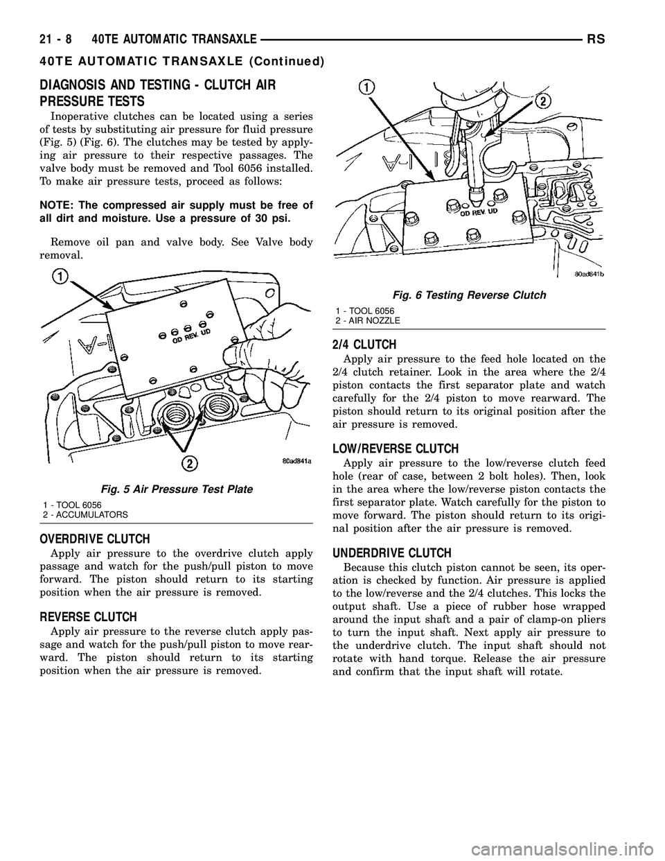
(Fig. 5) (Fig. 6). The clutches may be tested by apply-
ing air pressure to their respective passages. The
valve body must be removed and Tool 6056 installed.
To make air pressure tests, proceed as follows:
NOTE: The compressed air supply must be free of
all dirt and moisture. Use a pressure of 30 psi.
Remove oil pan and valve body. See Valve body
removal.
OVERDRIVE CLUTCH
Apply air pressure to the overdrive clutch apply
passage and watch for the push/pull piston to move
forward. The piston should return to its starting
position when the air pressure is removed.
REVERSE CLUTCH
Apply air pressure to the reverse clutch apply pas-
sage and watch for the push/pull piston to move rear-
ward. The piston should return to its starting
position when the air pressure is removed.
2/4 CLUTCH
Apply air pressure to the feed hole located on the
2/4 clutch retainer. Look in the area where the 2/4
piston contacts the first separator plate and watch
carefully for the 2/4 piston to move rearward. The
piston should return to its original position after the
air pressure is removed.
LOW/REVERSE CLUTCH
Apply air pressure to the low/reverse clutch feed
hole (rear of case, between 2 bolt holes). Then, look
in the area where the low/reverse piston contacts the
first separator plate. Watch carefully for the piston to
move forward. The piston should return to its origi-
nal position after the air pressure is removed.
UNDERDRIVE CLUTCH
Because this clutch piston cannot be seen, its oper-
ation is checked by function. Air pressure is applied
to the low/reverse and the 2/4 clutches. This locks the
output shaft. Use a piece of rubber hose wrapped
around the input shaft and a pair of clamp-on pliers
to turn the input shaft. Next apply air pressure to
the underdrive clutch. The input shaft should not
rotate with hand torque. Release the air pressure
and confirm that the input shaft will rotate.
Fig. 5 Air Pressure Test Plate
1 - TOOL 6056
2 - ACCUMULATORS
Fig. 6 Testing Reverse Clutch
1 - TOOL 6056
2 - AIR NOZZLE
21 - 8 40TE AUTOMATIC TRANSAXLERS
40TE AUTOMATIC TRANSAXLE (Continued)
Page 1475 of 2339

NOTE: Depending on engine application, some
accumulators will have two springs and others will
have one spring. The springs are color-coded
according to application and year. When disassem-
bling, mark accumulator spring location to ease
assembly.
(10) Remove underdrive and overdrive accumula-
tors (Fig. 22).
(11) Remove low/reverse accumulator snap ring
(Fig. 23).(12) Remove low/reverse accumulator plug (Fig.
24).
(13) Remove low/reverse accumulator piston using
suitable pliers (Fig. 25). Remove piston and springs
(Fig. 26).
Fig. 22 Underdrive and Overdrive Accumulators
1 - OVERDRIVE PISTON AND SPRING
2 - UNDERDRIVE PISTON AND SPRING
Fig. 23 Remove Low/Reverse Accumulator Snap
Ring
1 - SNAP RING
2 - PLUG
Fig. 24 Remove Low/Reverse Accumulator Plug
1 - ADJUSTABLE PLIERS
2 - PLUG
Fig. 25 Low/Reverse Accumulator Piston
1 - ACCUMULATOR PISTON
21 - 14 40TE AUTOMATIC TRANSAXLERS
40TE AUTOMATIC TRANSAXLE (Continued)
Page 1476 of 2339

(14) Measure input shaft end play. Place transaxle
so input shaft is vertical. Set up end play set and
dial indicator as shown in (Fig. 27).Input shaft end
play should be within 0.13-0.64 mm (0.005-0.025
in.)If outside of this range, a #4 thrust plate change
is required. Record indicator reading for reference
upon reassembly.(15) Remove oil pump-to-case bolts (Fig. 28).
CAUTION: Be sure input speed sensor is removed
before removing oil pump.
(16) Install pullers Tool C-3752 as shown in (Fig.
29).
Fig. 26 Low/Reverse Accumulator
1 - PISTON
2 - RETURN SPRINGS
Fig. 27 Measure Input Shaft End Play Using Tool
8266ÐTypical
1 - TOOL 8266±8
2 - TOOL 8266±2
3 - TOOL C-3339
Fig. 28 Remove Oil Pump-to-Case Bolts
1 - PUMP ATTACHING BOLTS
2 - PUMP HOUSING
Fig. 29 Install Tool C-3752
1 - PULLERS TOOL C-3752
2 - PUMP
RS40TE AUTOMATIC TRANSAXLE21-15
40TE AUTOMATIC TRANSAXLE (Continued)
Page 1509 of 2339

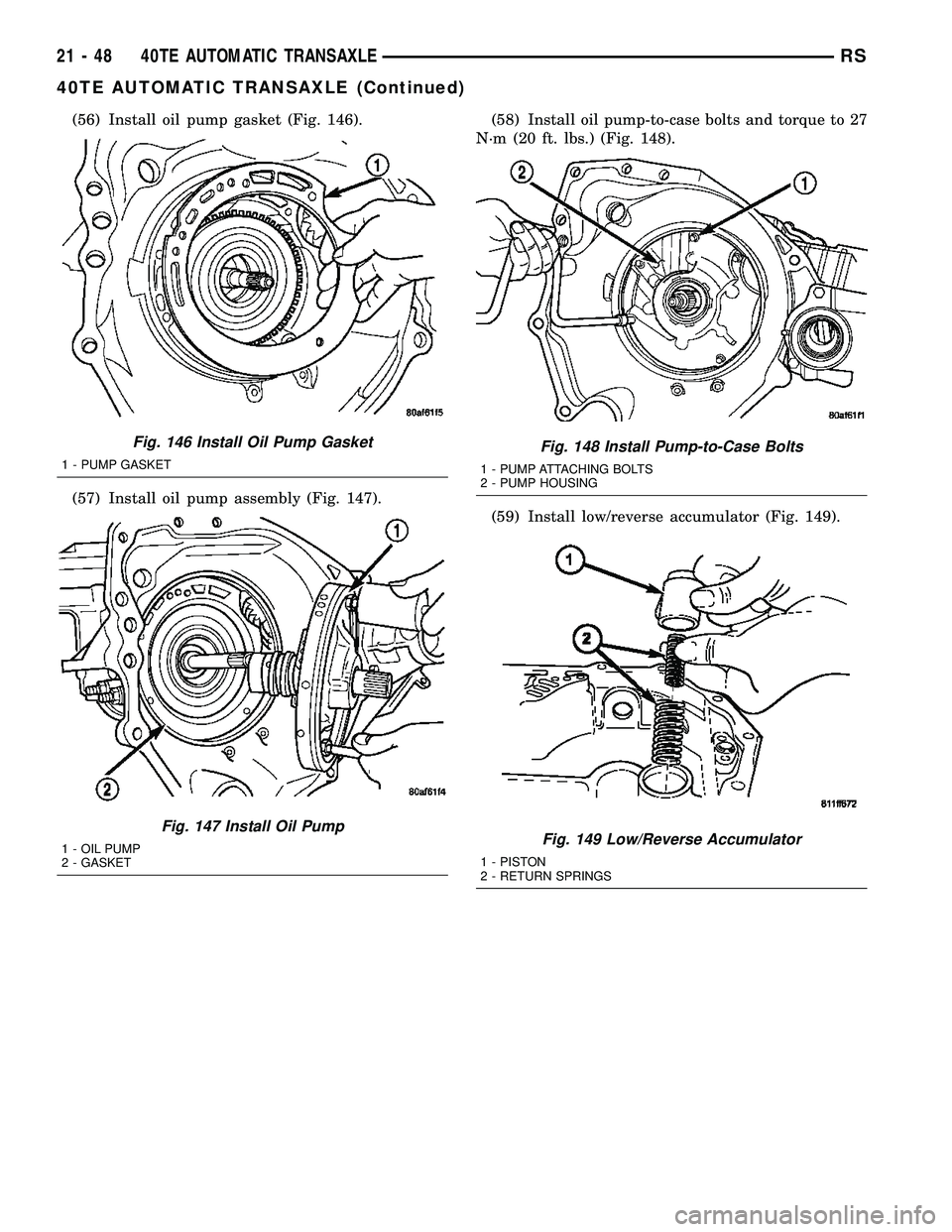
(56) Install oil pump gasket (Fig. 146).
(57) Install oil pump assembly (Fig. 147).(58) Install oil pump-to-case bolts and torque to 27
N´m (20 ft. lbs.) (Fig. 148).
(59) Install low/reverse accumulator (Fig. 149).
Fig. 146 Install Oil Pump Gasket
1 - PUMP GASKET
Fig. 147 Install Oil Pump
1 - OIL PUMP
2 - GASKET
Fig. 148 Install Pump-to-Case Bolts
1 - PUMP ATTACHING BOLTS
2 - PUMP HOUSING
Fig. 149 Low/Reverse Accumulator
1 - PISTON
2 - RETURN SPRINGS
21 - 48 40TE AUTOMATIC TRANSAXLERS
40TE AUTOMATIC TRANSAXLE (Continued)
Page 1510 of 2339

(60) Install low/reverse accumulator plug (Fig.
150).
(61) Install low/reverse accumulator snap ring
(Fig. 151).NOTE: Depending on engine application, some
accumulators will have two springs, and others will
have one spring. The springs are color-coded for
application and year.
(62) Install underdrive and overdrive accumulators
and springs (Fig. 152).
(63) Install valve body to transaxle (Fig. 153).
Rotate manual valve shaft fully clockwise to ease
installation. Make sure park rod rollers are posi-
tioned within park guide bracket.
Fig. 150 Install Low/Reverse Accumulator Plug
1 - ADJUSTABLE PLIERS
2 - PLUG
Fig. 151 Install Low/Reverse Accumulator Snap
Ring
1 - SNAP RING
2 - PLUG
Fig. 152 Underdrive and Overdrive Accumulators
1 - OVERDRIVE PISTON AND SPRING
2 - UNDERDRIVE PISTON AND SPRING
Fig. 153 Valve Body Removal/Installation
1 - VALVE BODY
RS40TE AUTOMATIC TRANSAXLE21-49
40TE AUTOMATIC TRANSAXLE (Continued)
Page 1534 of 2339

ACCUMULATOR
DESCRIPTION
The 4XTE underdrive, overdrive, low/reverse, and
2/4 clutch hydraulic circuits each contain an accumu-
lator. An accumulator typically consists of a piston,
return spring(s), and a cover or plug. The overdrive
and underdrive accumulators are located within the
transaxle case, and are retained by the valve body
(Fig. 164).
The low reverse accumulator (Fig. 165) is also
located within the transaxle case, but the assembly is
retained by a cover and a snap-ring.
The 2/4 accumulator is located in the valve body. It
is retained by a cover and retaining screws (Fig.
166).
OPERATION
The function of an accumulator is to cushion the
application of a frictional clutch element. When pres-
surized fluid is applied to a clutch circuit, the appli-
cation force is dampened by fluid collecting in therespective accumulator chamber against the piston
and spring(s). The intended result is a smooth, firm
clutch application.
Fig. 164 Underdrive and Overdrive Accumulators
1 - OVERDRIVE PISTON AND SPRING
2 - UNDERDRIVE PISTON AND SPRING
Fig. 165 Low/Reverse Accumulator
1 - PISTON
2 - RETURN SPRINGS
Fig. 166 2/4 Accumulator Assembly
1 - VALVE BODY
2 - RETAINER PLATE
3 - DETENT SPRING
4 - RETURN SPRINGS
5 - PISTON
RS40TE AUTOMATIC TRANSAXLE21-73
Page 1543 of 2339

FLUID
STANDARD PROCEDURE
FLUID LEVEL AND CONDITION CHECK
NOTE: Only transmission fluid of the type labeled
Mopar ATF+4 (Automatic Transmission Fluid)
should be used in this transaxle.
FLUID LEVEL CHECK
The transmission sump has a fluid level indicator
(dipstick) to check oil similar to most automatic
transmissions. It is located on the left side of the
engine. Be sure to wipe all dirt from dipstick handle
before removing.
The torque converter fills in both the P Park and N
Neutral positions. Place the selector lever in P Park
to be sure that the fluid level check is accurate.The
engine should be running at idle speed for at
least one minute, with the vehicle on level
ground.At normal operating temperature 82É C
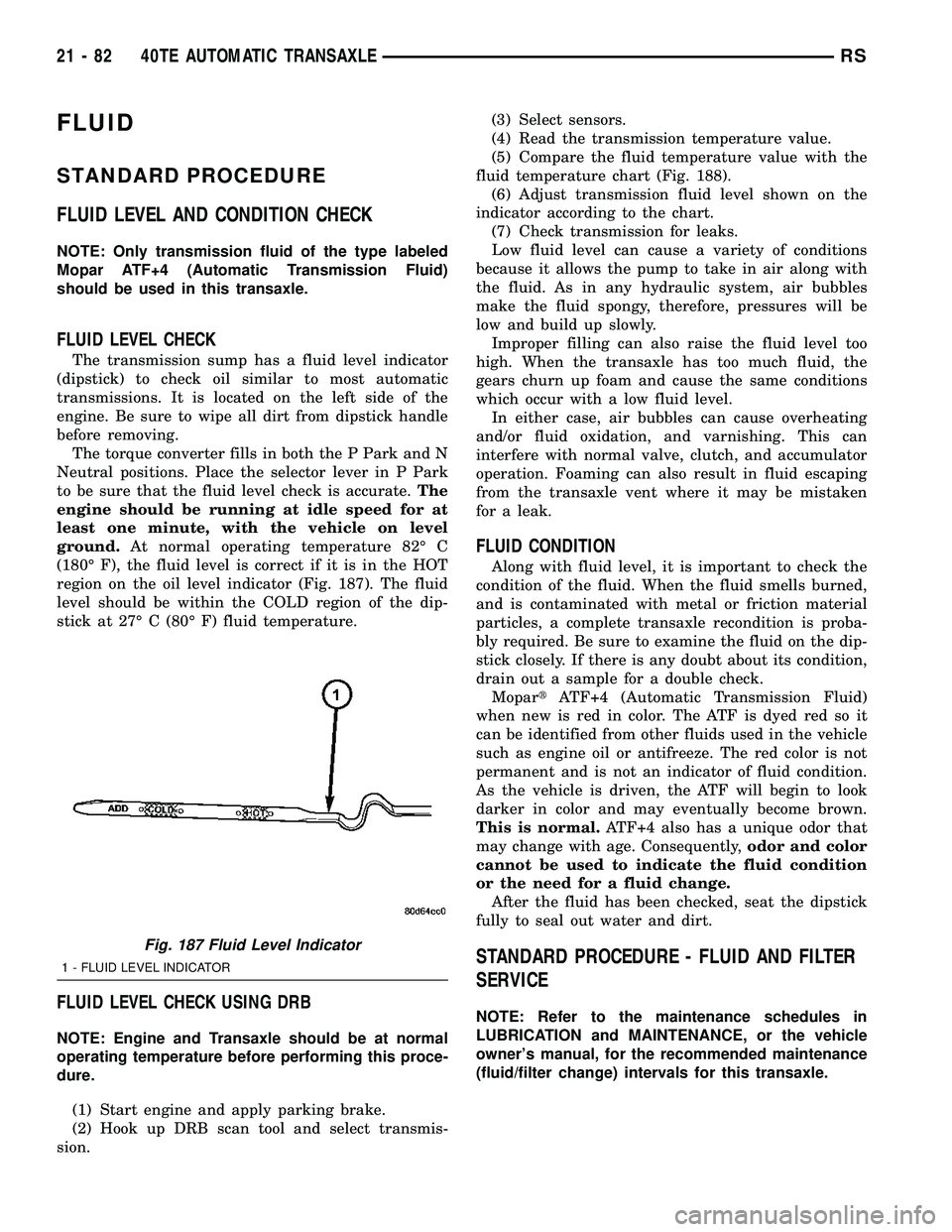
(180É F), the fluid level is correct if it is in the HOT
region on the oil level indicator (Fig. 187). The fluid
level should be within the COLD region of the dip-
stick at 27É C (80É F) fluid temperature.
FLUID LEVEL CHECK USING DRB
NOTE: Engine and Transaxle should be at normal
operating temperature before performing this proce-
dure.
(1) Start engine and apply parking brake.
(2) Hook up DRB scan tool and select transmis-
sion.(3) Select sensors.
(4) Read the transmission temperature value.
(5) Compare the fluid temperature value with the
fluid temperature chart (Fig. 188).
(6) Adjust transmission fluid level shown on the
indicator according to the chart.
(7) Check transmission for leaks.
Low fluid level can cause a variety of conditions
because it allows the pump to take in air along with
the fluid. As in any hydraulic system, air bubbles
make the fluid spongy, therefore, pressures will be
low and build up slowly.
Improper filling can also raise the fluid level too
high. When the transaxle has too much fluid, the
gears churn up foam and cause the same conditions
which occur with a low fluid level.
In either case, air bubbles can cause overheating
and/or fluid oxidation, and varnishing. This can
interfere with normal valve, clutch, and accumulator
operation. Foaming can also result in fluid escaping
from the transaxle vent where it may be mistaken
for a leak.
FLUID CONDITION
Along with fluid level, it is important to check the
condition of the fluid. When the fluid smells burned,
and is contaminated with metal or friction material
particles, a complete transaxle recondition is proba-
bly required. Be sure to examine the fluid on the dip-
stick closely. If there is any doubt about its condition,
drain out a sample for a double check.
MopartATF+4 (Automatic Transmission Fluid)
when new is red in color. The ATF is dyed red so it
can be identified from other fluids used in the vehicle
such as engine oil or antifreeze. The red color is not
permanent and is not an indicator of fluid condition.
As the vehicle is driven, the ATF will begin to look
darker in color and may eventually become brown.
This is normal.ATF+4 also has a unique odor that
may change with age. Consequently,odor and color
cannot be used to indicate the fluid condition
or the need for a fluid change.
After the fluid has been checked, seat the dipstick
fully to seal out water and dirt.
STANDARD PROCEDURE - FLUID AND FILTER
SERVICE
NOTE: Refer to the maintenance schedules in
LUBRICATION and MAINTENANCE, or the vehicle
owner's manual, for the recommended maintenance
(fluid/filter change) intervals for this transaxle.
Fig. 187 Fluid Level Indicator
1 - FLUID LEVEL INDICATOR
21 - 82 40TE AUTOMATIC TRANSAXLERS
Page 1593 of 2339

VALVE BODY
DESCRIPTION
The valve body assembly consists of a cast alumi-
num valve body, a separator plate, and transfer
plate. The valve body contains valves and check balls
that control fluid delivery to the torque converter
clutch, solenoid/pressure switch assembly, and fric-
tional clutches. The valve body contains the following
components (Fig. 310):
²Regulator valve
²Solenoid switch valve
²Manual valve
²Converter clutch switch valve
²Converter clutch control valve
²Torque converter regulator valve
²Low/Reverse switch valve
In addition, the valve body also contains the ther-
mal valve, #2,3&4 check balls, the #5 (overdrive)
check valve and the 2/4 accumulator assembly. (Refer
to 21 - TRANSMISSION/TRANSAXLE/AUTOMATIC
- 41TE/VALVE BODY - DISASSEMBLY)
OPERATION
NOTE: Refer to the Hydraulic Schematics for a
visual aid in determining valve location, operation
and design.
REGULATOR VALVE
The regulator valve controls hydraulic pressure in
the transaxle. It receives unregulated pressure from
the pump, which works against spring tension to
maintain oil at specific pressures. A system of sleeves
and ports allows the regulator valve to work at one of
three predetermined pressure levels. Regulated oil
pressure is also referred to as ªline pressure.º
SOLENOID SWITCH VALVE
The solenoid switch valve controls line pressure
from the LR/CC solenoid. In one position, it allows
the low/reverse clutch to be pressurized. In the other,
it directs line pressure to the converter control and
converter clutch valves.
Fig. 310 Valve Body Assembly
1 - VALVE BODY 5 - MANUAL VALVE
2 - T/C REGULATOR VALVE 6 - CONVERTER CLUTCH SWITCH VALVE
3 - L/R SWITCH VALVE 7 - SOLENOID SWITCH VALVE
4 - CONVERTER CLUTCH CONTROL VALVE 8 - REGULATOR VALVE
21 - 132 40TE AUTOMATIC TRANSAXLERS
Page 1596 of 2339

DISASSEMBLY
NOTE: If valve body assembly is being recondi-
tioned, the PCM/TCM Quick Learn Procedure must
be performed. (Refer to 8 - ELECTRICAL/ELEC-
TRONIC CONTROL MODULES/TRANSMISSION
CONTROL MODULE - STANDARD PROCEDURE)
(1) Remove manual shaft seal (Fig. 317).
(2) Remove Transmission Range Sensor retaining
screw (Fig. 318).(3) Remove Manual Shaft/Rooster Comb and
Transmission Range Sensor (Fig. 319).
(4) Remove 2/4 Accumulator Retaining Plate (Fig.
320).
Fig. 317 Manual Shaft Seal
1 - SEAL
2 - MANUAL SHAFT
Fig. 318 Remove Transmission Range Sensor
1 - TRANSMISSION RANGE SENSOR
2 - MANUAL VALVE CONTROL PIN
3 - RETAINING SCREW
Fig. 319 Manual Shaft/Rooster Comb and
Transmission Range Sensor
1 - TRANSMISSION RANGE SENSOR
2 - MANUAL SHAFT
3 - ROOSTER COMB
Fig. 320 2/4 Accumulator Retaining Plate
1 - 2±4 ACCUMULATOR RETAINING PLATE
2 - DETENT SPRING
RS40TE AUTOMATIC TRANSAXLE21 - 135
VALVE BODY (Continued)