accumulator CHRYSLER VOYAGER 2005 Service Manual
[x] Cancel search | Manufacturer: CHRYSLER, Model Year: 2005, Model line: VOYAGER, Model: CHRYSLER VOYAGER 2005Pages: 2339, PDF Size: 59.69 MB
Page 200 of 2339
START-UP CYCLE
When the ignition is turned on, a popping sound
and a slight brake pedal movement may be noticed.
The ABS warning lamp will also be on for up to 5
seconds after the ignition is turned on. When the
vehicle is first driven off, a humming may be heard
or felt by the driver at approximately 20±40 kph
(12±25 mph). All of these conditions are a normal
function of ABS as the system is performing a diag-
nosis check.
PREMATURE ABS CYCLING
Symptoms of premature ABS cycling include: click-
ing sounds from the solenoid valves; pump/motor
running; and pulsations in the brake pedal. Prema-
ture ABS cycling can occur at any braking rate of the
vehicle and on any type of road surface. Neither the
red BRAKE warning lamp, nor the amber ABS warn-
ing lamp, illuminate and no fault codes are stored in
the CAB.
Premature ABS cycling is a condition that needs to
be correctly assessed when diagnosing problems with
the antilock brake system. It may be necessary to use
a DRB scan tool to detect and verify premature ABS
cycling.
Check the following common causes when diagnos-
ing premature ABS cycling: damaged tone wheels;
incorrect tone wheels; damaged steering knuckle
wheel speed sensor mounting bosses; loose wheel
speed sensor mounting bolts; excessive tone wheel
runout; or an excessively large tone wheel-to-wheel
speed sensor air gap. Give special attention to these
components when diagnosing a vehicle exhibiting
premature ABS cycling.
After diagnosing the defective component, repair or
replace it as required. When the component repair or
replacement is completed, test drive the vehicle to
verify that premature ABS cycling has been cor-
rected.
OPERATION - ELECTRONIC VARIABLE BRAKE
PROPORTIONING
Upon entry into EVBP the inlet valve for the rear
brake circuit is switched on so that the fluid supply
from the master cylinder is shut off. In order to
decrease the rear brake pressure, the outlet valve for
the rear brake circuit is pulsed. This allows fluid to
enter the low pressure accumulator (LPA) in the
hydraulic control unit (HCU) resulting in a drop in
fluid pressure to the rear brakes. In order to increase
the rear brake pressure, the outlet valve is switched
off and the inlet valve is pulsed. This increases the
pressure to the rear brakes. This back-and-forth pro-
cess will continue until the required slip difference is
obtained. At the end of EVBP braking (brakes
released) the fluid in the LPA drains back to themaster cylinder by switching on the outlet valve and
draining through the inlet valve check valve. At the
same time the inlet valve is switched on in case of
another brake application.
The EVBP will remain functional during many
ABS fault modes. If both the red BRAKE and amber
ABS warning indicators are illuminated, the EVBP
may not be functioning.
OPERATION - TRACTION CONTROL SYSTEM
The traction control module monitors wheel speed.
During acceleration, if the module detects front
(drive) wheel slip and the brakes are not applied, the
module enters traction control mode. Traction control
operation proceeds in the following order:
(1) Close the normally open isolation valves.
(2) Start the pump/motor and supply volume and
pressure to the front (drive) hydraulic circuit. (The
pump/motor runs continuously during traction con-
trol operation.)
(3) Open and close the build and decay valves to
maintain minimum wheel slip and maximum trac-
tion.
The cycling of the build and decay valves during
traction control is similar to that during antilock
braking, except the valves work to control wheel spin
by applying the brakes, whereas the ABS function is
to control wheel skid by releasing the brakes.
If the brakes are applied at anytime during a trac-
tion control cycle, the brake lamp switch triggers the
controller to switch off traction control.
HYDRAULIC SHUTTLE VALVES
Two pressure relief hydraulic shuttle valves allow
pressure and volume to return to the master cylinder
reservoir when not consumed by the build and decay
valves. These valves are necessary because the
pump/motor supplies more volume than the system
requires.
TRACTION CONTROL LAMP
The traction control system is enabled at each igni-
tion cycle. It may be turned off by depressing the
Traction Control Off switch button when the ignition
is in the ON position. The traction control function
lamp (TRAC OFF) illuminates immediately upon
depressing the button.
The traction control function lamp illuminates dur-
ing a traction control cycle, displaying TRAC.
If the CAB calculates that the brake temperatures
are high, the traction control system becomes inoper-
ative until a time-out period has elapsed. During this
ªthermo-protection mode,º the traction control func-
tion lamp illuminates TRAC OFF; note that no trou-
ble code is registered.
RSBRAKES - ABS5-89
BRAKES - ABS (Continued)
Page 206 of 2339
(2) Disconnect traction control switch harness from
column harness (Fig. 5).
(3) Using an ohmmeter, check for continuity
between pins 1 and 2. With the switch actuated,
there should be continuity between the two pins.
With the switch off, there should be no continuity.
REMOVAL
The traction control switch is located in the upper
shroud. (Refer to 19 - STEERING/COLUMN/UPPER
SHROUD - REMOVAL)
INSTALLATION
The traction control switch is located in the upper
shroud. (Refer to 19 - STEERING/COLUMN/UPPER
SHROUD - INSTALLATION)
HYDRAULIC/MECHANICAL
OPERATION - HYDRAULIC CIRCUITS AND
VALVES
The hydraulic fluid control valves control the flow
of pressurized brake fluid to the wheel brakes during
the different modes of ABS braking. The following
paragraphs explain how this works. For purposes of
explanation only, it is assumed that only the right
front wheel is experiencing antilock braking; the fol-
lowing diagrams show only the right front wheel in
an antilock braking operation.
NORMAL BRAKING HYDRAULIC CIRCUIT AND
SOLENOID VALVE FUNCTION
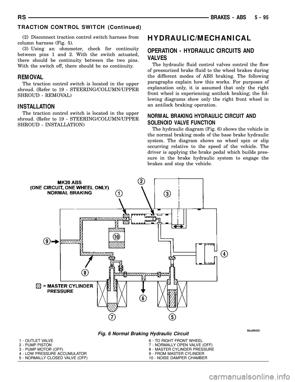
The hydraulic diagram (Fig. 6) shows the vehicle in
the normal braking mode of the base brake hydraulic
system. The diagram shows no wheel spin or slip
occurring relative to the speed of the vehicle. The
driver is applying the brake pedal which builds pres-
sure in the brake hydraulic system to engage the
brakes and stop the vehicle.
Fig. 6 Normal Braking Hydraulic Circuit
1 - OUTLET VALVE
2 - PUMP PISTON
3 - PUMP MOTOR (OFF)
4 - LOW PRESSURE ACCUMULATOR
5 - NORMALLY CLOSED VALVE (OFF)6 - TO RIGHT FRONT WHEEL
7 - NORMALLY OPEN VALVE (OFF)
8 - MASTER CYLINDER PRESSURE
9 - FROM MASTER CYLINDER
10 - NOISE DAMPER CHAMBER
RSBRAKES - ABS5-95
TRACTION CONTROL SWITCH (Continued)
Page 207 of 2339

ABS PRIMARY HYDRAULIC CIRCUIT AND
SOLENOID VALVE FUNCTION (ABS WITHOUT
TRACTION CONTROL)
The hydraulic diagram (Fig. 7) shows the vehicle in
the ABS braking mode. The diagram shows one
wheel is slipping because the driver is attempting to
stop the vehicle at a faster rate than is allowed by
the surface on which the tires are riding.
²The normally open and normally closed valves
modulate (build/decay) the brake hydraulic pressure
as required.
²The pump/motor is switched on so that the
brake fluid from the low pressure accumulators is
returned to the master cylinder circuits.
²The brake fluid is routed to either the master
cylinder or the wheel brake depending on the posi-
tion of the normally open valve.
Fig. 7 ABS Without Traction Control - Primary Hydraulic Circuit
1 - OUTLET VALVE
2 - PUMP PISTON
3 - PUMP MOTOR (ON)
4 - LOW PRESSURE ACCUMULATOR PRESSURE
5 - LOW PRESSURE ACCUMULATOR
6 - NORMALLY CLOSED VALVE (MODULATING)
7 - TO RIGHT FRONT WHEEL8 - NORMALLY OPEN VALVE (MODULATING)
9 - FROM MASTER CYLINDER
10 - MASTER CYLINDER PRESSURE
11 - CONTROLLED WHEEL PRESSURE
12 - PUMP INTERSTAGE PRESSURE
13 - NOISE DAMPER CHAMBER
5 - 96 BRAKES - ABSRS
HYDRAULIC/MECHANICAL (Continued)
Page 208 of 2339
ABS SECONDARY HYDRAULIC CIRCUIT AND
SOLENOID VALVE FUNCTION (ABS WITHOUT
TRACTION CONTROL)
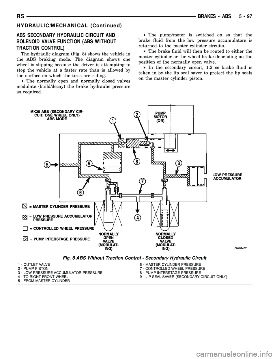
The hydraulic diagram (Fig. 8) shows the vehicle in
the ABS braking mode. The diagram shows one
wheel is slipping because the driver is attempting to
stop the vehicle at a faster rate than is allowed by
the surface on which the tires are riding.
²The normally open and normally closed valves
modulate (build/decay) the brake hydraulic pressure
as required.²The pump/motor is switched on so that the
brake fluid from the low pressure accumulators is
returned to the master cylinder circuits.
²The brake fluid will then be routed to either the
master cylinder or the wheel brake depending on the
position of the normally open valve.
²In the secondary circuit, 1.2 cc brake fluid is
taken in by the lip seal saver to protect the lip seals
on the master cylinder piston.
Fig. 8 ABS Without Traction Control - Secondary Hydraulic Circuit
1 - OUTLET VALVE
2 - PUMP PISTON
3 - LOW PRESSURE ACCUMULATOR PRESSURE
4 - TO RIGHT FRONT WHEEL
5 - FROM MASTER CYLINDER6 - MASTER CYLINDER PRESSURE
7 - CONTROLLED WHEEL PRESSURE
8 - PUMP INTERSTAGE PRESSURE
9 - LIP SEAL SAVER (SECONDARY CIRCUIT ONLY)
RSBRAKES - ABS5-97
HYDRAULIC/MECHANICAL (Continued)
Page 209 of 2339

NORMAL BRAKING HYDRAULIC CIRCUIT,
SOLENOID VALVE, AND SHUTTLE VALVE
FUNCTION (ABS WITH TRACTION CONTROL)
The hydraulic diagram (Fig. 9) shows a vehicle
with traction control in the normal braking mode.
The diagram shows no wheel spin or slip occurring
relative to the speed of the vehicle. The driver is
applying the brake pedal which builds pressure in
the brake hydraulic system to engage the brakes and
stop the vehicle. the hydraulic shuttle valve closes
with every brake pedal application so pressure is not
created at the inlet to the pump/motor.
Fig. 9 ABS With Traction Control - Normal Braking Hydraulic Circuit
1 - OUTLET VALVE
2 - PUMP PISTON
3 - PUMP MOTOR (OFF)
4 - SUCTION VALVE
5 - LOW PRESSURE ACCUMULATOR
6 - NORMALLY CLOSED VALVE (OFF)
7 - TO RIGHT FRONT WHEEL8 - NORMALLY OPEN VALVE (OFF)
9 - NORMALLY OPEN ASR VALVE (OFF)
10 - FROM MASTER CYLINDER
11 - HYDRAULIC SHUTTLE VALVE
12 - MASTER CYLINDER PRESSURE
13 - NOISE DAMPER CHAMBER
5 - 98 BRAKES - ABSRS
HYDRAULIC/MECHANICAL (Continued)
Page 210 of 2339

ABS BRAKING HYDRAULIC CIRCUIT, SOLENOID
VALVE, AND SHUTTLE VALVE FUNCTION (ABS
WITH TRACTION CONTROL)
The hydraulic diagram (Fig. 10) shows the vehicle
in the ABS braking mode. The diagram shows one
wheel is slipping because the driver is attempting to
stop the vehicle at a faster rate than is allowed by
the surface on which the tires are riding.
²The hydraulic shuttle valve closes upon brake
application so that the pump/motor cannot siphon
brake fluid from the master cylinder.²The normally open and normally closed valves
modulate (build/decay) the brake hydraulic pressure
as required.
²The pump/motor is switched on so that the
brake fluid from the low pressure accumulators is
returned to the master cylinder circuits.
²The brake fluid is routed to either the master
cylinder or the wheel brake depending on the posi-
tion of the normally open valve.
Fig. 10 ABS With Traction Control - ABS Braking Hydraulic Circuit
1 - OUTLET VALVE
2 - PUMP PISTON
3 - PUMP MOTOR (ON)
4 - SUCTION VALVE
5 - LOW PRESSURE ACCUMULATOR
6 - NORMALLY CLOSED VALVE (MODULATING)
7 - TO RIGHT FRONT WHEEL
8 - NORMALLY OPEN VALVE (MODULATING)9 - NORMALLY OPEN ASR VALVE (OFF)
10 - FROM MASTER CYLINDER
11 - HYDRAULIC SHUTTLE VALVE
12 - MASTER CYLINDER PRESSURE
13 - CONTROLLED WHEEL PRESSURE
14 - LOW PRESSURE ACCUMULATOR PRESSURE
15 - PUMP INTERSTAGE PRESSURE
16 - NOISE DAMPER CHAMBER
RSBRAKES - ABS5-99
HYDRAULIC/MECHANICAL (Continued)
Page 211 of 2339

ABS TRACTION CONTROL HYDRAULIC CIRCUIT,
SOLENOID VALVE, AND SHUTTLE VALVE
FUNCTION (ABS WITH TRACTION CONTROL)
The hydraulic diagram (Fig. 11) shows the vehicle
in the ABS braking mode. The diagram shows a drive
wheel is spinning and brake pressure is required to
reduce its speed.
²The normally open ASR valve is energized to iso-
late the brake fluid being pumped from the master
cylinder and to isolate the driven wheel.
²The normally open ASR valve bypasses the
pump output back to the master cylinder at a fixed
pressure setting.
²The normally open and normally closed valves
modulate (build/decay) the brake pressure as
required to the spinning wheel.
HCU (HYDRAULIC CONTROL
UNIT)
DESCRIPTION
The hydraulic control unit (HCU) is mounted to
the CAB as part of the ICU (Fig. 22). The HCU con-
trols the flow of brake fluid to the brakes using a
series of valves and accumulators. A pump/motor is
mounted on the HCU to supply build pressure to the
brakes during an ABS stop.
The HCU on a vehicle equipped with ABS and
traction control has a valve block housing that is
approximately 1 inch longer on the low pressure fluid
accumulators side than a HCU on a vehicle that is
equipped with only ABS.
Fig. 11 Traction Control Hydraulic Circuit
1 - OUTLET VALVE
2 - PUMP PISTON
3 - PUMP MOTOR (ON)
4 - LOW PRESSURE ACCUMULATOR PRESSURE
5 - LOW PRESSURE ACCUMULATOR
6 - NORMALLY CLOSED VALVE (MODULATING)
7 - TO RIGHT FRONT WHEEL (SPINNING)
8 - NORMALLY OPEN VALVE (MODULATING)
9 - NORMALLY OPEN ASR VALVE ON (REGULATING)10 - FROM MASTER CYLINDER
11 - HYDRAULIC SHUTTLE VALVE
12 - CONTROLLED WHEEL PRESSURE
13 - SUCTION VALVE
14 - PUMP INTERSTAGE PRESSURE
15 - NOISE DAMPER CHAMBER
16 - MASTER CYLINDER PRESSURE
17 - PUMP PRESSURE
5 - 100 BRAKES - ABSRS
HYDRAULIC/MECHANICAL (Continued)
Page 212 of 2339
For more information, (Refer to 5 - BRAKES/HY-
DRAULIC/MECHANICAL/ICU (INTEGRATED CON-
TROL UNIT) - DESCRIPTION)
OPERATION
For information on the operation of the HCU as a
whole, refer to Hydraulic Circuits And Valve Opera-
tion which can be found elsewhere in this section.
For information on the operation of the components
within the HCU, refer to the following three topics.
VALVES AND SOLENOIDS
The valve block contains four inlet valves and four
outlet valves. The inlet valves are spring-loaded in
the open position and the outlet valves are spring-
loaded in the closed position during normal braking.
The fluid is allowed to flow from the master cylinder
to the wheel brakes.
During an ABS stop, these valves cycle to maintain
the proper slip ratio for each wheel. The inlet valve
closes preventing further pressure increase and the
outlet valve opens to provide a path from the wheel
brake to the HCU accumulators and pump/motor.
This releases (decays) pressure from the wheel brake,
thus releasing the wheel from excessive slippage.
Once the wheel is no longer slipping, the outlet valve
is closed and the inlet valve is opened to reapply
(build) pressure.
On vehicles with traction control, there is an extra
set of valves and solenoids. The ASR valves, mounted
in the HCU valve block, are normally in the open
position and close only when the traction control is
applied.
These isolator valves are used to isolate the rear
(non-driving) wheels of the vehicle from the hydraulic
pressure that the HCU pump/motor is sending to the
front (driving) wheels when traction control is being
applied. The rear brakes need to be isolated from the
master cylinder when traction control is being
applied so the rear wheels do not drag. For more
information, refer to Traction Control System in this
section.
BRAKE FLUID ACCUMULATORS
There are two fluid accumulators in the HCU±one
for the primary hydraulic circuit and one for the sec-
ondary hydraulic circuit. Each hydraulic circuit uses
a 5 cc accumulator.
The fluid accumulators temporarily store brake
fluid that is removed from the wheel brakes during
an ABS cycle. This stored fluid is used by the pump/
motor to provide build pressure for the brake hydrau-
lic system. When the antilock stop is complete, the
accumulators are drained by the pump/motor.
On ABS-only vehicles, there is a mini-accumulator
on the secondary hydraulic circuit that protects the
master cylinder seals during an ABS stop, and there
is a noise dampening chamber on the primary circuit.
On ABS with traction control vehicles, there are
two noise dampening chambers in the HCU.
PUMP/MOTOR
There are two pump assemblies in the HCUÐone
for the primary hydraulic circuit and one for the sec-
ondary hydraulic circuit. Both pumps are driven by a
common electric motor. This DC-type motor is inte-
gral to the HCU and is controlled by the CAB.
The pump/motor provides the extra amount of
brake fluid needed during antilock braking. Brake
fluid is released to the accumulators when the outlet
valve is opened during an antilock stop. The pump
mechanism consists of two opposing pistons operated
by an eccentric camshaft. In operation, one piston
draws fluid from the accumulators, and the opposing
piston pumps fluid to the master cylinder circuits.
When the antilock stop is complete, the pump/motor
drains the accumulators.
The CAB may turn on the pump/motor when an
antilock stop is detected. The pump/motor continues
to run during the antilock stop and is turned off after
the stop is complete. Under some conditions, the
pump/motor runs to drain the accumulators during
the next drive-off.
The pump/motor is not a serviceable item; if it
requires replacement, the HCU must be replaced.
RSBRAKES - ABS5 - 101
HCU (HYDRAULIC CONTROL UNIT) (Continued)
Page 213 of 2339
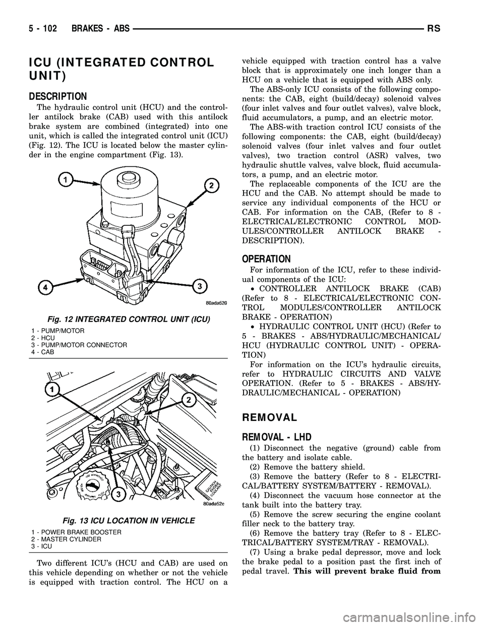
ICU (INTEGRATED CONTROL
UNIT)
DESCRIPTION
The hydraulic control unit (HCU) and the control-
ler antilock brake (CAB) used with this antilock
brake system are combined (integrated) into one
unit, which is called the integrated control unit (ICU)
(Fig. 12). The ICU is located below the master cylin-
der in the engine compartment (Fig. 13).
Two different ICU's (HCU and CAB) are used on
this vehicle depending on whether or not the vehicle
is equipped with traction control. The HCU on avehicle equipped with traction control has a valve
block that is approximately one inch longer than a
HCU on a vehicle that is equipped with ABS only.
The ABS-only ICU consists of the following compo-
nents: the CAB, eight (build/decay) solenoid valves
(four inlet valves and four outlet valves), valve block,
fluid accumulators, a pump, and an electric motor.
The ABS-with traction control ICU consists of the
following components: the CAB, eight (build/decay)
solenoid valves (four inlet valves and four outlet
valves), two traction control (ASR) valves, two
hydraulic shuttle valves, valve block, fluid accumula-
tors, a pump, and an electric motor.
The replaceable components of the ICU are the
HCU and the CAB. No attempt should be made to
service any individual components of the HCU or
CAB. For information on the CAB, (Refer to 8 -
ELECTRICAL/ELECTRONIC CONTROL MOD-
ULES/CONTROLLER ANTILOCK BRAKE -
DESCRIPTION).
OPERATION
For information of the ICU, refer to these individ-
ual components of the ICU:
²CONTROLLER ANTILOCK BRAKE (CAB)
(Refer to 8 - ELECTRICAL/ELECTRONIC CON-
TROL MODULES/CONTROLLER ANTILOCK
BRAKE - OPERATION)
²HYDRAULIC CONTROL UNIT (HCU) (Refer to
5 - BRAKES - ABS/HYDRAULIC/MECHANICAL/
HCU (HYDRAULIC CONTROL UNIT) - OPERA-
TION)
For information on the ICU's hydraulic circuits,
refer to HYDRAULIC CIRCUITS AND VALVE
OPERATION. (Refer to 5 - BRAKES - ABS/HY-
DRAULIC/MECHANICAL - OPERATION)
REMOVAL
REMOVAL - LHD
(1) Disconnect the negative (ground) cable from
the battery and isolate cable.
(2) Remove the battery shield.
(3) Remove the battery (Refer to 8 - ELECTRI-
CAL/BATTERY SYSTEM/BATTERY - REMOVAL).
(4) Disconnect the vacuum hose connector at the
tank built into the battery tray.
(5) Remove the screw securing the engine coolant
filler neck to the battery tray.
(6) Remove the battery tray (Refer to 8 - ELEC-
TRICAL/BATTERY SYSTEM/TRAY - REMOVAL).
(7) Using a brake pedal depressor, move and lock
the brake pedal to a position past the first inch of
pedal travel.This will prevent brake fluid from
Fig. 12 INTEGRATED CONTROL UNIT (ICU)
1 - PUMP/MOTOR
2 - HCU
3 - PUMP/MOTOR CONNECTOR
4 - CAB
Fig. 13 ICU LOCATION IN VEHICLE
1 - POWER BRAKE BOOSTER
2 - MASTER CYLINDER
3 - ICU
5 - 102 BRAKES - ABSRS
Page 1462 of 2339

TRANSMISSION/TRANSAXLE
TABLE OF CONTENTS
page page
40TE AUTOMATIC TRANSAXLE..............141TE AUTOMATIC TRANSAXLE............146
40TE AUTOMATIC TRANSAXLE
TABLE OF CONTENTS
page page
40TE AUTOMATIC TRANSAXLE
DESCRIPTION..........................2
OPERATION............................4
DIAGNOSIS AND TESTING
DIAGNOSIS AND TESTING - 4XTE
TRANSAXLE GENERAL DIAGNOSIS........5
DIAGNOSIS AND TESTING - ROAD TEST....5
DIAGNOSIS AND TESTING - HYDRAULIC
PRESSURE TESTS.....................6
DIAGNOSIS AND TESTING - CLUTCH AIR
PRESSURE TESTS.....................8
DIAGNOSIS AND TESTING - TORQUE
CONVERTER HOUSING FLUID LEAKAGE....9
REMOVAL.............................9
DISASSEMBLY.........................12
ASSEMBLY............................29
INSTALLATION.........................51
SCHEMATICS AND DIAGRAMS
4XTE TRANSAXLE HYDRAULIC
SCHEMATICS........................54
SPECIFICATIONS - 41TE TRANSAXLE.......66
SPECIAL TOOLS.......................68
ACCUMULATOR
DESCRIPTION.........................73
OPERATION...........................73
DRIVING CLUTCHES
DESCRIPTION.........................74
OPERATION...........................74
FINAL DRIVE
DESCRIPTION.........................74
OPERATION...........................75
DISASSEMBLY.........................75
ASSEMBLY............................78
ADJUSTMENTS
DIFFERENTIAL BEARING PRELOAD
MEASUREMENT AND ADJUSTMENT......79FLUID
STANDARD PROCEDURE
FLUID LEVEL AND CONDITION CHECK....82
STANDARD PROCEDURE - FLUID AND
FILTER SERVICE......................82
GEAR SHIFT CABLE
REMOVAL.............................84
HOLDING CLUTCHES
DESCRIPTION.........................86
OPERATION...........................86
INPUT CLUTCH ASSEMBLY
DISASSEMBLY.........................86
ASSEMBLY............................95
OIL PUMP
DESCRIPTION........................110
OPERATION..........................110
DISASSEMBLY........................110
ASSEMBLY...........................112
PLANETARY GEARTRAIN
DESCRIPTION........................112
OPERATION..........................112
SEAL - OIL PUMP
REMOVAL............................113
INSTALLATION........................113
SHIFT INTERLOCK SOLENOID
DESCRIPTION........................113
OPERATION..........................114
DIAGNOSIS AND TESTING - BRAKE/
TRANSMISSION SHIFT INTERLOCK
SOLENOID..........................115
REMOVAL............................115
INSTALLATION........................116
SOLENOID/PRESSURE SWITCH ASSY
DESCRIPTION........................117
OPERATION..........................118
REMOVAL............................118
INSTALLATION........................119
RSTRANSMISSION/TRANSAXLE21-1