change time CHRYSLER VOYAGER 2005 User Guide
[x] Cancel search | Manufacturer: CHRYSLER, Model Year: 2005, Model line: VOYAGER, Model: CHRYSLER VOYAGER 2005Pages: 2339, PDF Size: 59.69 MB
Page 265 of 2339
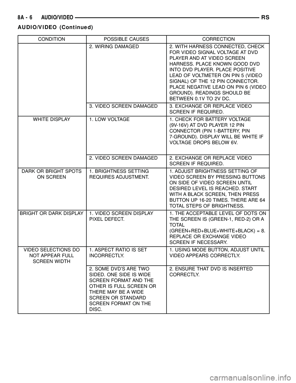
CONDITION POSSIBLE CAUSES CORRECTION
2. WIRING DAMAGED 2. WITH HARNESS CONNECTED, CHECK
FOR VIDEO SIGNAL VOLTAGE AT DVD
PLAYER AND AT VIDEO SCREEN
HARNESS. PLACE KNOWN GOOD DVD
INTO DVD PLAYER. PLACE POSITIVE
LEAD OF VOLTMETER ON PIN 5 (VIDEO
SIGNAL) OF THE 12 PIN CONNECTOR.
PLACE NEGATIVE LEAD ON PIN 6 (VIDEO
GROUND). READINGS SHOULD BE
BETWEEN 0.1V TO 2V DC.
3. VIDEO SCREEN DAMAGED 3. EXCHANGE OR REPLACE VIDEO
SCREEN IF REQUIRED.
WHITE DISPLAY 1. LOW VOLTAGE 1. CHECK FOR BATTERY VOLTAGE
(9V-16V) AT DVD PLAYER 12 PIN
CONNECTOR (PIN 1-BATTERY, PIN
7-GROUND). DISPLAY WILL BE WHITE IF
VOLTAGE DROPS BELOW 6V.
2. VIDEO SCREEN DAMAGED 2. EXCHANGE OR REPLACE VIDEO
SCREEN IF REQUIRED.
DARK OR BRIGHT SPOTS
ON SCREEN1. BRIGHTNESS SETTING
REQUIRES ADJUSTMENT.1. ADJUST BRIGHTNESS SETTING OF
VIDEO SCREEN BY PRESSING BUTTONS
ON SIDE OF VIDEO SCREEN UNTIL
DESIRED LEVEL IS REACHED. START
WITH A BLACK SCREEN, THEN PRESS
BUTTON UP 16-20 TIMES. THERE ARE 64
TOTAL STEPS OF BRIGHTNESS.
BRIGHT OR DARK DISPLAY 1. VIDEO SCREEN DISPLAY
PIXEL DEFECT.1. THE ACCEPTABLE LEVEL OF DOTS ON
THE SCREEN IS (GREEN-1, RED-2) OR A
TOTAL
(GREEN+RED+BLUE+WHITE+BLACK) = 8.
REPLACE OR EXCHANGE VIDEO
SCREEN IF NECESSARY.
VIDEO SELECTIONS DO
NOT APPEAR FULL
SCREEN WIDTH1. ASPECT RATIO IS SET
INCORRECTLY.1. USING MODE BUTTON, ADJUST UNTIL
VIDEO APPEARS CORRECTLY.
2. SOME DVD'S ARE TWO
SIDED. ONE SIDE IS WIDE
SCREEN FORMAT AND THE
OTHER IS FULL SCREEN OR
THERE MAY BE A WIDE
SCREEN OR STANDARD
SCREEN FORMAT ON THE
DISC.2. ENSURE THAT DVD IS INSERTED
CORRECTLY.
8A - 6 AUDIO/VIDEORS
AUDIO/VIDEO (Continued)
Page 270 of 2339

ANTENNA - NAVIGATION
RADIO
REMOVAL
(1) Disconnect and isolate the battery negative
cable.
(2) Remove the radio (Refer to 8 - ELECTRICAL/
AUDIO/RADIO - REMOVAL).
(3) Disconnect antenna from radio (Fig. 7). Remove
tape securing antenna to air duct, and remove
antenna (Fig. 8).
INSTALLATION
(1) Secure antenna to air duct.
(2) Connect antenna to radio.
(3) Install radio (Refer to 8 - ELECTRICAL/AU-
DIO/RADIO - INSTALLATION).
(4) Connect battery negative cable.
CD CHANGER
DESCRIPTION
The 6 Disc In-Dash CD Changer (if equipped) is
located in the instrument panel below the radio. The
remote changer does not use a cartridge or magazine
for the CD's. Up to 6 CD's can be directly loaded into
this unit.
OPERATION
Due to its compact design, the CD changer can
carry out only one operation at a time. For example,
you can not load a new disc while playing another at
the same time. Each operation happens sequentially.
The radio unit provides control over all features of
the CD changer with the exception of the CD load
and eject functions, which are controlled by buttons
located on the front of the CD changer. All features
you would expect, such as Disc Up/Down, Track
Up/Down, Random and Scan are controlled by the
radio, which also displays all relevant CD changer
information on the radio display.
The CD changer contains a Eject button, six disc
buttons, an indicator LED for each of the six disc
positions as well as an illuminated disc opening. The
individual LED indicates whether a CD is currently
loaded in that particular chamber of the CD changer.
Pressing the individual button for a particular cham-
ber, then the Eject button will eject a disc currently
present in that chamber. If the chamber is currently
empty, actuating the individual button will position
that chamber to receive and load a new disc in that
chamber.
REMOVAL
(1) Disconnect and isolate the battery negative
cable.
(2) Remove screws holding CD changer.
(3) Disconnect the wire connector from the back of
the CD changer.
(4) Remove the CD changer from the vehicle (Fig.
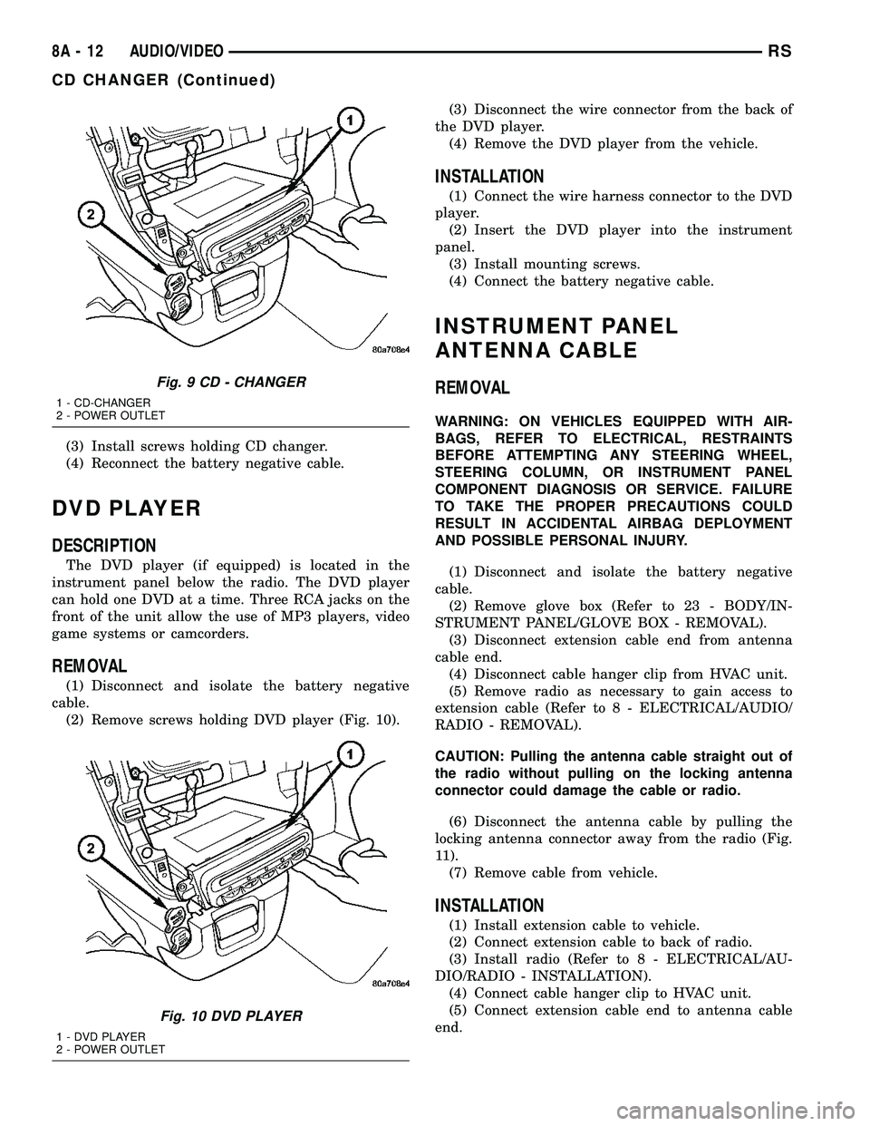
9).
INSTALLATION
(1) Reconnect the wire connector to the CD
changer.
(2) Insert the CD changer into the instrument
panel.
NOTE: Use care when inserting CD changer so that
cable is not pinched or trapped against instrument
panel.
Fig. 7 NAVIGATION ANTENNA
Fig. 8 NAVIGATION ANTENNA MOUNTING
RSAUDIO/VIDEO8A-11
Page 271 of 2339
(3) Install screws holding CD changer.
(4) Reconnect the battery negative cable.
DVD PLAYER
DESCRIPTION
The DVD player (if equipped) is located in the
instrument panel below the radio. The DVD player
can hold one DVD at a time. Three RCA jacks on the
front of the unit allow the use of MP3 players, video
game systems or camcorders.
REMOVAL
(1) Disconnect and isolate the battery negative
cable.
(2) Remove screws holding DVD player (Fig. 10).(3) Disconnect the wire connector from the back of
the DVD player.
(4) Remove the DVD player from the vehicle.
INSTALLATION
(1) Connect the wire harness connector to the DVD
player.
(2) Insert the DVD player into the instrument
panel.
(3) Install mounting screws.
(4) Connect the battery negative cable.
INSTRUMENT PANEL
ANTENNA CABLE
REMOVAL
WARNING: ON VEHICLES EQUIPPED WITH AIR-
BAGS, REFER TO ELECTRICAL, RESTRAINTS
BEFORE ATTEMPTING ANY STEERING WHEEL,
STEERING COLUMN, OR INSTRUMENT PANEL
COMPONENT DIAGNOSIS OR SERVICE. FAILURE
TO TAKE THE PROPER PRECAUTIONS COULD
RESULT IN ACCIDENTAL AIRBAG DEPLOYMENT
AND POSSIBLE PERSONAL INJURY.
(1) Disconnect and isolate the battery negative
cable.
(2) Remove glove box (Refer to 23 - BODY/IN-
STRUMENT PANEL/GLOVE BOX - REMOVAL).
(3) Disconnect extension cable end from antenna
cable end.
(4) Disconnect cable hanger clip from HVAC unit.
(5) Remove radio as necessary to gain access to
extension cable (Refer to 8 - ELECTRICAL/AUDIO/
RADIO - REMOVAL).
CAUTION: Pulling the antenna cable straight out of
the radio without pulling on the locking antenna
connector could damage the cable or radio.
(6) Disconnect the antenna cable by pulling the
locking antenna connector away from the radio (Fig.
11).
(7) Remove cable from vehicle.
INSTALLATION
(1) Install extension cable to vehicle.
(2) Connect extension cable to back of radio.
(3) Install radio (Refer to 8 - ELECTRICAL/AU-
DIO/RADIO - INSTALLATION).
(4) Connect cable hanger clip to HVAC unit.
(5) Connect extension cable end to antenna cable
end.
Fig. 9 CD - CHANGER
1 - CD-CHANGER
2 - POWER OUTLET
Fig. 10 DVD PLAYER
1 - DVD PLAYER
2 - POWER OUTLET
8A - 12 AUDIO/VIDEORS
CD CHANGER (Continued)
Page 284 of 2339
┬▓System diagnostics - diagnosis and error han-
dling (sensors, display, module).
┬▓Data exchange over the Programmable Commu-
nication Interface (PCI) data bus.
OPERATION
The module has a number of functions:
┬▓Supply voltage to the sensors and display.
┬▓Disconnection of the display with bus idle and
over voltage Vmax.
┬▓Triggering the sensors.
┬▓Analyze echo delay times and calculate obstacle
distances.
┬▓Bi-directional data communication to the display
for diagnosis.
┬▓System diagnostics - diagnosis and error han-
dling (sensors, display, module).
┬▓Data exchange over the Programmable Commu-
nication Interface (PCI) data bus.
The system detection length from the rear of the
vehicle is 0.3 meters to 1.5 meters. This area extends
around the rear side of the vehicle. The system detec-
tion height from the ground is 0.2 meters to about
1.5 meters. The radio mutes when the system acti-
vates its audible tone.When the driver selects Reverse, the system scans
for objects behind the vehicle using four sensors
located in the rear bumper. Objects can be detected
from up to 1.5 meters. A warning display above the
rear window provides both visible and audible warn-
ings indicating the range of the object.
The system is active only when the vehicle is in
reverse for vehicle speeds less than 16 Km/h (10
mph). If the vehicles Parking/Emergency Brake is
applied, the system is deactivated.
The display contains two sets of yellow and red
Light Emitting Diode's (LED's) that the driver can
see as they look over their shoulder while backing
up. Each side of the vehicle has its own warning
LED's. The system provides a visual warning by illu-
minating one or more yellow LED's as the vehicle
gets closer to the object. As the vehicle continues to
approaches the object, one red LED is illuminated
and the system emits a series of short beeps. The
tone will remain constant and both red LED's are
illuminated once the vehicle is within 12 inches (30.5
cm) of the object.
The system can be turned ON or OFF through the
Electronic Vehicle Information Center (EVIC) when
the vehicle is in PARK. If the park assist system is
turned OFF, a single chime will sound and the EVIC
will display the following message ªREAR PARK
ASSIST OFF┬║, when the vehicle is in reverse.
┬▓Ensure that the rear bumper is free of dirt and
debris to keep the system operating properly.
┬▓Jackhammers, large trucks, and other vibrations
could affect the performance of the system.
┬▓Ensure that the parking brake is not applied.
If ªService Park Assist Systemº appears in the
EVIC after making sure the rear bumper is clean,
proceed to diagnose the system using a scan tool and
the appropriate diagnostic information.
To diagnose the Park Assist Module, use a scan
tool and the appropriate body diagnostic information.
REMOVAL
(1) Open hood.
(2)
Disconnect and isolate the battery negative cable.
(3) Remove the left quarter trim panel (Refer to 23
- BODY/INTERIOR/QUARTER TRIM PANEL -
REMOVAL).
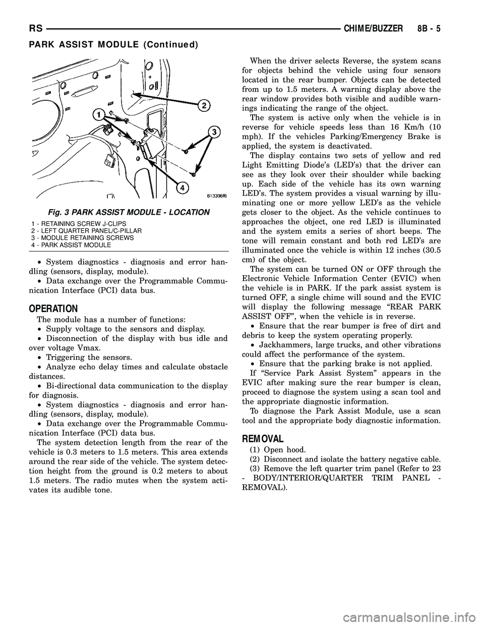
Fig. 3 PARK ASSIST MODULE - LOCATION
1 - RETAINING SCREW J-CLIPS
2 - LEFT QUARTER PANEL/C-PILLAR
3 - MODULE RETAINING SCREWS
4 - PARK ASSIST MODULE
RSCHIME/BUZZER8B-5
PARK ASSIST MODULE (Continued)
Page 298 of 2339
By comparing the two inputs, the PCM can deter-
mine transaxle gear ratio. This is important to the
CVI calculation because the PCM determines CVIs
by monitoring how long it takes for a gear change to
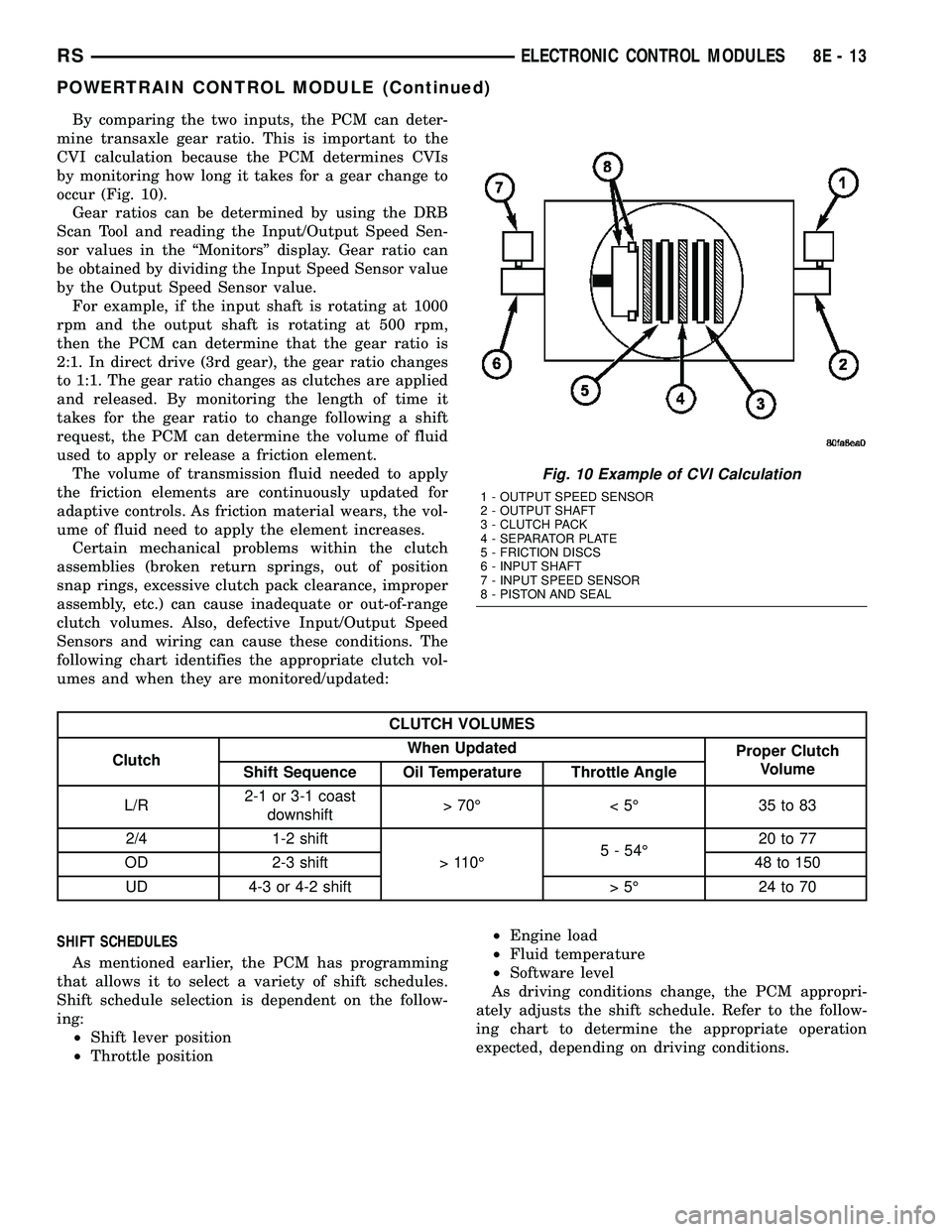
occur (Fig. 10).
Gear ratios can be determined by using the DRB
Scan Tool and reading the Input/Output Speed Sen-
sor values in the ªMonitorsº display. Gear ratio can
be obtained by dividing the Input Speed Sensor value
by the Output Speed Sensor value.
For example, if the input shaft is rotating at 1000
rpm and the output shaft is rotating at 500 rpm,
then the PCM can determine that the gear ratio is
2:1. In direct drive (3rd gear), the gear ratio changes
to 1:1. The gear ratio changes as clutches are applied
and released. By monitoring the length of time it
takes for the gear ratio to change following a shift
request, the PCM can determine the volume of fluid
used to apply or release a friction element.
The volume of transmission fluid needed to apply
the friction elements are continuously updated for
adaptive controls. As friction material wears, the vol-
ume of fluid need to apply the element increases.
Certain mechanical problems within the clutch
assemblies (broken return springs, out of position
snap rings, excessive clutch pack clearance, improper
assembly, etc.) can cause inadequate or out-of-range
clutch volumes. Also, defective Input/Output Speed
Sensors and wiring can cause these conditions. The
following chart identifies the appropriate clutch vol-
umes and when they are monitored/updated:
CLUTCH VOLUMES
ClutchWhen Updated
Proper Clutch
Volume
Shift Sequence Oil Temperature Throttle Angle
L/R2-1 or 3-1 coast
downshift>70É <5É 35to83
2/4 1-2 shift
> 110É5 - 54É20 to 77
OD 2-3 shift 48 to 150
UD 4-3 or 4-2 shift > 5É 24 to 70
SHIFT SCHEDULES
As mentioned earlier, the PCM has programming
that allows it to select a variety of shift schedules.
Shift schedule selection is dependent on the follow-
ing:
┬▓Shift lever position
┬▓Throttle position┬▓Engine load
┬▓Fluid temperature
┬▓Software level
As driving conditions change, the PCM appropri-
ately adjusts the shift schedule. Refer to the follow-
ing chart to determine the appropriate operation
expected, depending on driving conditions.
Fig. 10 Example of CVI Calculation
1 - OUTPUT SPEED SENSOR
2 - OUTPUT SHAFT
3 - CLUTCH PACK
4 - SEPARATOR PLATE
5 - FRICTION DISCS
6 - INPUT SHAFT
7 - INPUT SPEED SENSOR
8 - PISTON AND SEAL
RSELECTRONIC CONTROL MODULES8E-13
POWERTRAIN CONTROL MODULE (Continued)
Page 314 of 2339
battery for a low electrolyte condition and before
returning the vehicle to service. (Refer to 8 - ELEC-
TRICAL/CHARGING - DIAGNOSIS AND TESTING)
for additional information.
The battery Group Size number, the Cold Cranking
Amperage (CCA) rating, and the Reserve Capacity
(RC) rating or Ampere-Hours (AH) rating can be
found on the original equipment battery label. Be
certain that a replacement battery has the correct
Group Size number, as well as CCA, and RC or AH
ratings that equal or exceed the original equipment
specification for the vehicle being serviced. (Refer to
8 - ELECTRICAL/BATTERY SYSTEM - SPECIFICA-
TIONS) for the proper factory-installed battery spec-
ifications.
OPERATION
The battery is designed to store electrical energy in
a chemical form. When an electrical load is applied to
the terminals of the battery, an electrochemical reac-
tion occurs. This reaction causes the battery to dis-
charge electrical current from its terminals. As the
battery discharges, a gradual chemical change takes
place within each cell. The sulfuric acid in the elec-
trolyte combines with the plate materials, causing
both plates to slowly change to lead sulfate. At the
same time, oxygen from the positive plate material
combines with hydrogen from the sulfuric acid, caus-
ing the electrolyte to become mainly water. The
chemical changes within the battery are caused by
the movement of excess or free electrons between the
positive and negative plate groups. This movement of
electrons produces a flow of electrical current
through the load device attached to the battery ter-
minals.
As the plate materials become more similar chem-
ically, and the electrolyte becomes less acid, the volt-
age potential of each cell is reduced. However, by
charging the battery with a voltage higher than that
of the battery itself, the battery discharging process
is reversed. Charging the battery gradually changes
the sulfated lead plates back into sponge lead and
lead dioxide, and the water back into sulfuric acid.
This action restores the difference in the electron
charges deposited on the plates, and the voltage
potential of the battery cells. For a battery to remain
useful, it must be able to produce high-amperage cur-
rent over an extended period. A battery must also be
able to accept a charge, so that its voltage potential
may be restored.
The battery is vented to release excess hydrogen
gas that is created when the battery is being charged
or discharged. However, even with these vents,
hydrogen gas can collect in or around the battery. If
hydrogen gas is exposed to flame or sparks, it may
ignite. If the electrolyte level is low, the battery mayarc internally and explode. If the battery is equipped
with removable cell caps, add distilled water when-
ever the electrolyte level is below the top of the
plates. If the battery cell caps cannot be removed, the
battery must be replaced if the electrolyte level
becomes low.
DIAGNOSIS AND TESTING
BATTERY
The battery must be completely charged and the
terminals should be properly cleaned and inspected
before diagnostic procedures are performed. (Refer to
8 - ELECTRICAL/BATTERY SYSTEM - CLEANING)
for the proper cleaning procedures, and (Refer to 8 -
ELECTRICAL/BATTERY SYSTEM - INSPECTION)
for the proper battery inspection procedures. (Refer
to 8 - ELECTRICAL/BATTERY SYSTEM/BATTERY -
STANDARD PROCEDURE) for the proper battery
charging procedures.
MICRO 420 BATTERY TESTER
The Micro 420 automotive battery tester is
designed to help the dealership technicians diagnose
the cause of a defective battery. Follow the instruc-
tion manual supplied with the tester or (Refer to 8 -
ELECTRICAL/BATTERY SYSTEM/BATTERY -
STANDARD PROCEDURE - USING THE MICRO
420 BATTERY TESTER) to properly diagnose a vehi-
cle
WARNING: IF THE BATTERY SHOWS SIGNS OF
FREEZING, LEAKING OR LOOSE POSTS, DO NOT
TEST, ASSIST-BOOST, OR CHARGE. THE BATTERY
MAY ARC INTERNALLY AND EXPLODE. PERSONAL
INJURY AND/OR VEHICLE DAMAGE MAY RESULT.
WARNING: EXPLOSIVE HYDROGEN GAS FORMS IN
AND AROUND THE BATTERY. DO NOT SMOKE,
USE FLAME, OR CREATE SPARKS NEAR THE BAT-
TERY. PERSONAL INJURY AND/OR VEHICLE DAM-
AGE MAY RESULT.
WARNING: THE BATTERY CONTAINS SULFURIC
ACID, WHICH IS POISONOUS AND CAUSTIC. AVOID
CONTACT WITH THE SKIN, EYES, OR CLOTHING.
IN THE EVENT OF CONTACT, FLUSH WITH WATER
AND CALL A PHYSICIAN IMMEDIATELY. KEEP OUT
OF THE REACH OF CHILDREN.
A battery that will not accept a charge is inopera-
tive, and must be replaced. Further testing is not
required. A fully-charged battery must be tested to
determine its cranking capacity. A battery that is ful-
RSBATTERY SYSTEM8F-9
BATTERY (Continued)
Page 413 of 2339
SELF-DIAGNOSTIC TEST
A self-diagnostic test is used to determine that the
electronics module is operating properly, and that all
the PCI data bus messages are being received for ini-
tial operation. Initiate the self-diagnostic test as fol-
lows:
(1) With the ignition switch in the Off position, on
Electronic Vehicle Information Center (EVIC) and
Compass Mini-Trip Computer (CMTC) equipped vehi-
cles simultaneously depress and hold theSTEPand
theRESETbuttons. On Compass Temperature Mod-
ule (CT) equipped vehicles depress theC/Tand the
US/Mpush buttons.
(2) Turn the ignition switch to the On position.
(3) Following completion of these tests, the elec-
tronics module will display one of the following mes-
sages:
a.Pass Self Test (EVIC only), PASS (CT,
CMTC)- The electronics module is working properly.
b.Failed Self Test (EVIC only), FAIL (CT,
CMTC)- The electronics module has an internal fail-
ure. The electronics module is faulty and must be
replaced.
NOTE: If the compass functions, but accuracy is
suspect, it may be necessary to perform a variation
adjustment. This procedure allows the compass
unit to accommodate variations in the earth's mag-
netic field strength, based on geographic location.
(Refer to 8 - ELECTRICAL/OVERHEAD CONSOLE -
STANDARD PROCEDURE - COMPASS VARIATION
ADJUSTMENT).
NOTE: If the compass reading display is blank and
only ªCALº appears in the display, demagnetizing
may be necessary to remove excessive residual
magnetic fields from the vehicle. (Refer to 8 - ELEC-
TRICAL/OVERHEAD CONSOLE - STANDARD PRO-
CEDURE - COMPASS DEMAGNETIZING).
STANDARD PROCEDURE
COMPASS CALIBRATION
CAUTION: Do not place any external magnets, such
as magnetic roof mount antennas, in the vicinity of
the compass. Do not use magnetic tools when ser-
vicing the overhead console.The electronic compass unit features a self-cali-
brating design, which simplifies the calibration pro-
cedure. This feature automatically updates the
compass calibration while the vehicle is being driven.
This allows the compass unit to compensate for small
changes in the residual magnetism the vehicle may
acquire during normal use. If the compass readings
appear to be erratic or out of calibration, perform the
following calibration procedure. Also, new service
replacement Electronic Modules (EVIC, CMTC, CT)
must have their compass calibrated using this proce-
dure. Do not attempt to calibrate the compass near
large metal objects such as other vehicles, large
buildings, or bridges; or, near overhead or under-
ground power lines.
NOTE: Whenever the compass is calibrated manu-
ally, the variance number must also be reset. (Refer
to 8 - ELECTRICAL/OVERHEAD CONSOLE - STAN-
DARD PROCEDURE - COMPASS VARIATION
ADJUSTMENT).
Calibrate the compass manually as follows:
(1) Turn the ignition switch to the On position. If
the compass/thermometer data is not currently being
displayed, momentarily depress and release the C/T
push button to reach the compass/thermometer dis-
play.
(2) On Electronic Vehicle Information Center
(EVIC) and Compass Mini-Trip Computer (CMTC)
equipped vehicles depress the Reset push button and
hold the button until ªCALº appears in the display.
This takes about ten seconds, and appears about five
seconds after ªVAR = XXº is displayed. On Compass
Temperature Module (CT) equipped vehicles depress
the C/T push button and US/M push button down
until ªCALº appears in the display. This takes about
ten seconds, and appears about five seconds after
ªVAR = XXº is displayed.
(3) Release the push button(s).
(4) Drive the vehicle on a level surface, away from
large metal objects and power lines, through three or
more complete circles at between five and eight kilo-
meters-per-hour (three and five miles-per-hour) for a
minimum of 48 seconds. The ªCALº message will dis-
appear from the display to indicate that the compass
is now calibrated.
NOTE: If the ªCALº message remains in the display,
either there is excessive magnetism near the com-
pass, or the unit is faulty. Repeat the calibration
procedure one more time.
8M - 4 OVERHEAD CONSOLERS
OVERHEAD CONSOLE (Continued)
Page 414 of 2339
NOTE: If the wrong direction is still indicated in the
compass display, the area selected for calibration
may be too close to a strong magnetic field. Repeat
the calibration procedure in another location.
COMPASS DEMAGNETIZING
A degaussing tool (Special Tool 6029) is used to
demagnetize, or degauss, the overhead console for-
ward mounting screw and the roof panel above the
overhead console. Equivalent units must be rated as
continuous duty for 110/115 volts and 60 Hz. They
must also have a field strength of over 350 gauss at 7
millimeters (0.25 inch) beyond the tip of the probe.
To demagnetize the roof panel and the overhead
console forward mounting screw, proceed as follows:
(1) Be certain that the ignition switch is in the Off
position, before you begin the demagnetizing proce-
dure.
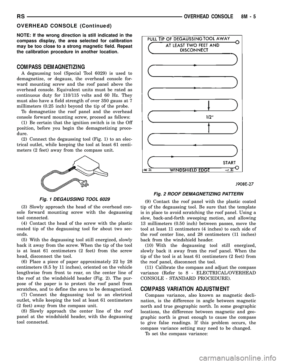
(2) Connect the degaussing tool (Fig. 1) to an elec-
trical outlet, while keeping the tool at least 61 centi-
meters (2 feet) away from the compass unit.
(3) Slowly approach the head of the overhead con-
sole forward mounting screw with the degaussing
tool connected.
(4) Contact the head of the screw with the plastic
coated tip of the degaussing tool for about two sec-
onds.
(5) With the degaussing tool still energized, slowly
back it away from the screw. When the tip of the tool
is at least 61 centimeters (2 feet) from the screw
head, disconnect the tool.
(6) Place a piece of paper approximately 22 by 28
centimeters (8.5 by 11 inches), oriented on the vehicle
lengthwise from front to rear, on the center line of
the roof at the windshield header (Fig. 2). The pur-
pose of the paper is to protect the roof panel from
scratches, and to define the area to be demagnetized.
(7) Connect the degaussing tool to an electrical
outlet, while keeping the tool at least 61 centimeters
(2 feet) away from the compass unit.
(8) Slowly approach the center line of the roof
panel at the windshield header, with the degaussing
tool connected.(9) Contact the roof panel with the plastic coated
tip of the degaussing tool. Be sure that the template
is in place to avoid scratching the roof panel. Using a
slow, back-and-forth sweeping motion, and allowing
13 millimeters (0.50 inch) between passes, move the
tool at least 11 centimeters (4 inches) to each side of
the roof center line, and 28 centimeters (11 inches)
back from the windshield header.
(10) With the degaussing tool still energized,
slowly back it away from the roof panel. When the
tip of the tool is at least 61 centimeters (2 feet) from
the roof panel, disconnect the tool.
(11) Calibrate the compass and adjust the compass
variance (Refer to 8 - ELECTRICAL/OVERHEAD
CONSOLE - STANDARD PROCEDURE).
COMPASS VARIATION ADJUSTMENT
Compass variance, also known as magnetic decli-
nation, is the difference in angle between magnetic
north and true geographic north. In some geographic
locations, the difference between magnetic and geo-
graphic north is great enough to cause the compass
to give false readings. If this problem occurs, the
compass variance setting may need to be changed.
To set the compass variance:
Fig. 1 DEGAUSSING TOOL 6029
Fig. 2 ROOF DEMAGNETIZING PATTERN
RSOVERHEAD CONSOLE8M-5
OVERHEAD CONSOLE (Continued)
Page 418 of 2339
┬▓RETRAIN TIRE SENSORS?- This program-
mable feature only applies to vehicles equipped with
the optional Tire Pressure Monitoring System. The
options include Yes and No. The default is No. When
Yes is selected, and the menu button is depressed the
EVIC will enter the training mode, starting with the
left front tire.
┬▓USE FACTORY SETTINGS?- The options
include Yes and No. The default is Yes. When yes is
selected all the programmable features will return to
there defaults and the rest of the programmable fea-
tures will not be displayed. If No is selected the rest
of the programmable features will be displayed at
there current chosen values. This feature will auto-
matically return to the Yes default under two condi-
tions. First, if no programmable features are changed
from there defaults. Second, if all the programmable
features equal there defaults.
┬▓AUTO DOOR LOCKS?- The options include
Yes and No. The default is Yes. When Yes is selected,
all doors and the liftgate lock automatically when
vehicle speed reaches 25 kilometers-per-hour (15
miles-per-hour). If YES is selected, a second program-
mable feature appears,AUTO UNLOCK ON EXIT?
- The options again include Yes and No. The default
is No. When Yes is selected, following each Auto Door
Lock event all doors and the liftgate will automati-
cally unlock when the driver door is opened, if the
vehicle is stopped and the transmission gear selector
is in Park or Neutral. The Auto Door Unlock event
will only occur once following each Auto Door Lock
event.
┬▓REMOTE UNLOCK- The options include
Driver Door 1st and All Doors. The default is Driver
Door 1st. When Diver Door 1st is selected, only the
driver door unlocks when the Unlock button of the
Remote Keyless Entry (RKE) transmitter is
depressed once. The Unlock button of the RKE trans-
mitter must be depressed twice to unlock all doors.
When All Doors is selected, all doors unlock when the
Unlock button of the RKE transmitter is depressed
once.
┬▓REMOTE LINKED TO MEMORY?- This pro-
grammable feature only applies to vehicles equipped
with the optional memory / heated system. The
options include Yes and No. The default is No. When
Yes is selected, the memory system will recall the
Driver 1 or Driver 2 memory settings assigned to the
RKE transmitter being used to unlock the vehicle.
When No is selected, the memory system will only
recall memory settings when the Driver 1 or Driver 2
push buttons of the memory switch on the driver side
front door trim panel are depressed.
┬▓SOUND HORN ON LOCK?- The options
include Yes and No. The default is No. When Yes is
selected, a short horn chirp will provide an audibleconfirmation when the RKE receiver recognizes a
valid Lock signal from an RKE transmitter. When No
is selected, no horn chirp will occur with the RKE
Lock event. This feature may be selected indepen-
dent of theFLASH LIGHTS WITH LOCKS?pro-
grammable feature.
┬▓FLASH LIGHTS WITH LOCKS?- The options
include Yes and No. The default is Yes. When Yes is
selected, a single flash of the hazard warning lamps
will provide an optical confirmation when the RKE
receiver recognizes a valid Lock signal from an RKE
transmitter, and two flashes of the same lamps will
occur when the RKE receiver recognizes a valid
Unlock signal from an RKE transmitter. When No is
selected, no lamp flash will occur with the RKE Lock
or Unlock event. This feature may be selected inde-
pendent of theSOUND HORN ON LOCK?pro-
grammable feature.
┬▓HEADLAMP DELAY =- The options include
Off, 30 Sec, 60 Sec, and 90 Sec. The default is 90 Sec.
When a time interval is selected, the headlamps will
remain on for that length of time when the head-
lamps are turned off after the ignition is turned off,
or if the Auto mode is selected on vehicles with the
Auto Headlamps option. When Off is selected, the
headlamp delay feature is disabled.
┬▓HEADLAMPS ON WITH WIPERS?- This pro-
grammable feature only applies to vehicles equipped
with the optional Auto Headlamps. The options
include Yes and No. The default is No. When Yes is
selected, the headlamps will turn on automatically
when the windshield wipers are turned on. The head-
lamps will turn off when the wipers are turned off,
as long as the headlamp switch is in the Auto or Off
positions. When No is selected, the headlamps will
only turn on if manually selected or if the Auto mode
is selected and the outside ambient light levels dic-
tate that they should be on.
┬▓POWER ACCESSORY DELAY?- The options
include Yes and No. The default is Yes. When No is
selected, the accessory powered components will turn
off automatically when the ignition key is turned off.
When Yes is selected, the accessory powered compo-
nents will remain on for 45 seconds when the igni-
tion key is turned off.
REMOVAL
(1) Disconnect and isolate the battery negative
cable.
(2) Remove overhead console. (Refer to 8 - ELEC-
TRICAL/OVERHEAD CONSOLE - REMOVAL).
(3) Remove the ten screws holding the Electronic
Vehicle Information Center (EVIC) module in the
overhead console.
(4) Remove EVIC module from console assembly.
RSOVERHEAD CONSOLE8M-9
ELECTRONIC VEHICLE INFO CENTER (Continued)
Page 419 of 2339

NOTE: If the EVIC module is being replaced, the tire
pressure monitoring system (if equipped) must be
retrained. (Refer to 22 - TIRES/WHEELS/TIRE PRES-
SURE MONITORING/SENSOR - STANDARD PROCE-
DURE)
INSTALLATION
(1) Position the Electronic Vehicle Information
Center (EVIC) module in the overhead console.
(2) Install the ten screws holding the EVIC module
in the overhead console.
(3) Install the overhead console (Refer to 8 -
ELECTRICAL/OVERHEAD CONSOLE - INSTALLA-
TION).
(4) Connect the battery negative cable.
NOTE: If the EVIC module is being replaced, the tire
pressure monitoring system (if equipped) must be
retrained. (Refer to 22 - TIRES/WHEELS/TIRE PRES-
SURE MONITORING/SENSOR - STANDARD PROCE-
DURE).
NOTE: If a new EVIC module has been installed, the
compass will have to be calibrated and the variance
set. (Refer to 8 - ELECTRICAL/OVERHEAD CON-
SOLE - STANDARD PROCEDURE - COMPASS CAL-
IBRATION).
COMPASS/MINI-TRIP
COMPUTER
DESCRIPTION
The Compass Mini-Trip Computer (CMTC) module
is located in the overhead console. The CMTC con-
sists of a electronic control module with a vacuum
fluorescent display (VFD) and function switches. The
CMTC consists of a electronic module that displays
compass, trip computer, and temperature features.
Actuating the STEP push button will cause the
CMTC to change mode of operation when the ignition
is ON. Example:
┬▓Average miles per gallon (ECO)
┬▓Distance to empty (DTE)
┬▓Instant miles per gallon (ECO)
┬▓Trip odometer (ODO)
┬▓Elapsed time (ET)
┬▓Blank
Actuating the C/T push button will cause the
CMTC to change to the Compass/Temperature dis-
play.
OPERATION
The Compass Mini-Trip Computer (CMTC) module
in the overhead console has buttons used to select
various functions. The CMTC selector buttons will
not operate until the ignition is in the RUN position.
When the ignition switch is first turned to the
RUN position the CMTC display;
┬▓Blanks momentarily
┬▓All segments of the VFD will light for one sec-
ond
┬▓Blanks momentarily
┬▓Returns to the last mode setting selected before
the ignition was last switched OFF.
DIAGNOSIS AND TESTING
COMPASS MINI-TRIP COMPUTER
Any diagnosis of the compass mini-trip com-
puter should begin with the use of the DRB IIIt
diagnostic tool. For information on the use of
the DRB IIIt, refer to the appropriate Diagnos-
tic Procedures information.
Compass Mini-Trip Computer (CMTC) data is
obtained from the Body Control Module (BCM) on
the Programmable Communications Interface (PCI)
Data Bus circuit. The CMTC will display dashes (- -)
for any of the screens it did not receive the bus mes-
sages. The label corresponding to the missing infor-
mation will be lit. If no CMTC data is displayed,
check the PCI Data Bus circuit communications and
the BCM. If the dimming level is improper check the
PCI Data Bus circuit.
REMOVAL
(1) Disconnect and isolate the battery negative
cable.
(2) Remove overhead console(Refer to 8 - ELEC-
TRICAL/OVERHEAD CONSOLE - REMOVAL).
(3) Remove the screws holding Compass Mini-Trip
Computer (CMTC) module in the overhead console.
(4) Remove CMTC module from the console assem-
bly.
INSTALLATION
(1) Position the compass mini-trip computer
(CMTC) module in the overhead console.
(2) Install the ten screws holding the CMTC mod-
ule in the overhead console.
(3) Install the overhead console (Refer to 8 -
ELECTRICAL/OVERHEAD CONSOLE - INSTALLA-
TION).
(4) Connect the battery negative cable.
8M - 10 OVERHEAD CONSOLERS
ELECTRONIC VEHICLE INFO CENTER (Continued)