set clock CHRYSLER VOYAGER 2005 Service Manual
[x] Cancel search | Manufacturer: CHRYSLER, Model Year: 2005, Model line: VOYAGER, Model: CHRYSLER VOYAGER 2005Pages: 2339, PDF Size: 59.69 MB
Page 154 of 2339
INSTALLATION
(1) Install adjustable pedals assembly under
instrument panel.
(2) Attach throttle cable to accelerator pedal using
cable retainer.
(3) Install two upper mounting bolts attaching
pedals assembly to steering column support bracket
on dash panel.Do not fully tighten at this time.
(4) Install four nuts attaching pedals assembly and
power brake booster to dash panel (Fig. 61).
(5) Tighten four booster mounting nuts and two
upper mounting bolts to 28 N´m (21 ft. lbs.) torque.
(6) Route pedal adjuster cable up and over right
side of pedals assembly and steering column bracket,
then down through hole in steering column bracket
as shown (Fig. 60). Attach end of cable to gear box.
(7) Place adjuster cable through loop on right side
of steering column bracket as shown (Fig. 60).
(8) Install booster input rod onto brake pedal pin
and install a NEW retaining clip.
(9) Connect wiring connector connecting vehicle
wiring harness to pedal wiring harness (Fig. 58).
(10) Connect routing clips retaining vehicle wiring
harness to pedal wiring harness (Fig. 58).
(11) Install brake lamp switch bracket on pedals
assembly. Tighten mounting nuts to 6 N´m (50 in.
lbs.) torque.
(12) Install dash seal silencer shell over steering
column intermediate shaft and fasten in place (Fig.
57).
(13) Install steering column onto lower mounting
studs with nuts started, then install column onto
upper mounting studs and install two upper mount-
ing nuts. Tighten upper, then lower mounting nuts to
12 N´m (105 in. lbs.) torque.
(14) Install column shaft coupling onto intermedi-
ate shaft and install pinch bolt. Make sure rounded
side of intermediate shaft is matched to the curva-
ture of the coupling. Tighten pinch bolt to 28 N´m
(250 in. lbs.) torque.
(15) Remove retainer holding steering wheel in
place on steering column.
(16) Attach shift cable to bracket on column.
(17) Connect shift cable end to shift lever mecha-
nism pin (Fig. 55).
(18) If equipped, connect PRNDL cable to end of
shift lever mechanism pin and column bracket (Fig.
55).(19) Connect column wiring harness connectors (as
equipped) to SKIM, BTSI solenoid, ignition switch,
multi-function switch, and clockspring.
(20) Install lower and upper steering column
shrouds. (Refer to 19 - STEERING/COLUMN/
LOWER SHROUD - INSTALLATION)
CAUTION: Do not reuse the original brake lamp
switch. The switch can only be adjusted once. That
is during initial installation of the switch. If the
switch is not adjusted properly or has been
removed for some service, a new switch must be
installed and adjusted.
(21) Install and adjust NEW brake lamp switch.
(Refer to 8 - ELECTRICAL/LAMPS/LIGHTING -
EXTERIOR/BRAKE LAMP SWITCH - INSTALLA-
TION)
(22) Install instrument panel lower left reinforce-
ment (Fig. 54).
(23) Attach hood release to lower left reinforce-
ment.
(24) Install knee blocker reinforcement plate (Fig.
53).
(25) Connect parking brake release link to release
handle.
(26) Install data link diagnostic connector to
mounting hole in reinforcement plate.
(27) Install lower steering column cover/knee
blocker (Fig. 53).
(28) Install throttle cable onto throttle body lever.
(Refer to 14 - FUEL SYSTEM/FUEL INJECTION/
THROTTLE CONTROL CABLE - INSTALLATION)
NOTE: When reconnecting the battery on a vehicle
that has had the airbag module removed, the fol-
lowing procedure should be used.
(29) Reconnect ground cable to negative post of
battery following special Diagnosis And Testing pro-
cedure. (Refer to 8 - ELECTRICAL/RESTRAINTS -
DIAGNOSIS AND TESTING)
(30) Test operation of adjustable pedals and all
functions that are steering column operated. If appli-
cable, reset radio and clock.
(31) Road test the vehicle to ensure proper opera-
tion of steering and brake systems.
RSBRAKES - BASE5-43
PEDALS - ADJUSTABLE (Continued)
Page 273 of 2339
OPERATION
The radio receiver operates on ignition switched
battery current that is available only when the igni-
tion switch is in the On or Accessory/Accessory Delay
positions. The electronic digital clock function of the
radio operates on fused battery current supplied
through the IOD fuse, regardless of the ignition
switch position.
For complete circuit diagrams, refer to the appro-
priate wiring information.
DIAGNOSIS AND TESTING
RADIO
WARNING: ON VEHICLES EQUIPPED WITH AIR-
BAGS, REFER TO ELECTRICAL, RESTRAINTS
BEFORE ATTEMPTING ANY STEERING WHEEL,
STEERING COLUMN, OR INSTRUMENT PANEL
COMPONENT DIAGNOSIS OR SERVICE. FAILURE
TO TAKE THE PROPER PRECAUTIONS COULD
RESULT IN ACCIDENTAL AIRBAG DEPLOYMENT
AND POSSIBLE PERSONAL INJURY.
Any diagnosis of the Audio system should
begin with the use of the DRB IIItdiagnostic
tool. For information on the use of the DRB
IIIt, refer to the appropriate Diagnostic Service
Manual.
Refer to the appropriate wiring information.
If the vehicle is equipped with remote radio
switches located on the back of the steering wheel
spokes, and the problem being diagnosed is related to
one of the symptoms listed below, be certain to check
the remote radio switches and circuits as described
in this group, prior to attempting radio diagnosis or
repair.
²Stations changing with no remote radio switch
input
²Radio memory presets not working properly
²Volume changes with no remote radio switch
input
²Remote radio switch buttons taking on other
functions
²CD player skipping tracks
²Remote radio switch inoperative.
CAUTION: The speaker output of the radio is a
ªfloating groundº system. Do not allow any speaker
lead to short to ground, as damage to the radio
may result.
(1) Check the fuse(s) in the junction block and the
Integrated Power Module (IPM). If OK, go to Step 2.
If not OK, repair the shorted circuit or component as
required and replace the faulty fuse(s).(2) Check for battery voltage at the fuse in the
(IPM). If OK, go to Step 3. If not OK, repair the open
circuit to the battery as required.
(3) Turn the ignition switch to the ON position.
Check for battery voltage at the fuse in the junction
block. If OK, go to Step 4. If not OK, repair the open
circuit to the ignition switch as required.
(4) Turn the ignition switch to the OFF position.
Remove the radio, but do not unplug the wire har-
ness connectors. Check for continuity between the
radio chassis and a good ground. There should be
continuity. If OK, go to Step 5. If not OK, repair the
open radio chassis ground circuit as required.
(5) Connect the battery negative cable. Turn the
ignition switch to the ON position. Check for battery
voltage at the fused ignition switch output circuit
cavity of the radio wire harness connector. If OK, go
to Step 6. If not OK, repair the open circuit as
required.
(6) Turn the ignition switch to the OFF position.
Check for battery voltage at the fused B(+) circuit
cavity of the radio wire harness connector. If OK,
replace the faulty radio. If not OK, repair the open
circuit to the Ignition-Off Draw (IOD) fuse as
required.
REMOVAL
(1) Disconnect and isolate the battery negative
cable.
(2) Remove cup holder.
(3) Remove trim panel above cupholder by pulling
straight out.
(4) Remove center instrument panel trim panel.
(5) Remove screws holding radio to instrument
panel.
(6) Pull radio rearward to gain access to the back
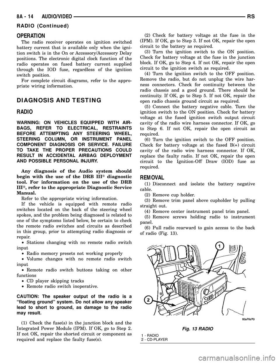
of radio (Fig. 13).
Fig. 13 RADIO
1 - RADIO
2 - CD-PLAYER
8A - 14 AUDIO/VIDEORS
RADIO (Continued)
Page 275 of 2339
REMOTE SWITCHES
DESCRIPTION
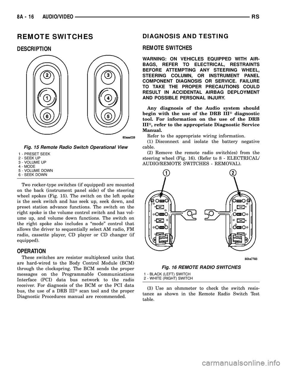
Two rocker-type switches (if equipped) are mounted
on the back (instrument panel side) of the steering
wheel spokes (Fig. 15). The switch on the left spoke
is the seek switch and has seek up, seek down, and
preset station advance functions. The switch on the
right spoke is the volume control switch and has vol-
ume up, and volume down functions. The switch on
the right spoke also includes a ªmodeº control that
allows the driver to sequentially select AM radio, FM
radio, cassette player, CD player or CD changer (if
equipped).
OPERATION
These switches are resistor multiplexed units that
are hard-wired to the Body Control Module (BCM)
through the clockspring. The BCM sends the proper
messages on the Programmable Communications
Interface (PCI) data bus network to the radio
receiver. For diagnosis of the BCM or the PCI data
bus, the use of a DRB IIItscan tool and the proper
Diagnostic Procedures manual are recommended.
DIAGNOSIS AND TESTING
REMOTE SWITCHES
WARNING: ON VEHICLES EQUIPPED WITH AIR-
BAGS, REFER TO ELECTRICAL, RESTRAINTS
BEFORE ATTEMPTING ANY STEERING WHEEL,
STEERING COLUMN, OR INSTRUMENT PANEL
COMPONENT DIAGNOSIS OR SERVICE. FAILURE
TO TAKE THE PROPER PRECAUTIONS COULD
RESULT IN ACCIDENTAL AIRBAG DEPLOYMENT
AND POSSIBLE PERSONAL INJURY.
Any diagnosis of the Audio system should
begin with the use of the DRB IIItdiagnostic
tool. For information on the use of the DRB
IIIt, refer to the appropriate Diagnostic Service
Manual.
Refer to the appropriate wiring information.
(1) Disconnect and isolate the battery negative
cable.
(2) Remove the remote radio switch(es) from the
steering wheel (Fig. 16). (Refer to 8 - ELECTRICAL/
AUDIO/REMOTE SWITCHES - REMOVAL).
(3) Use an ohmmeter to check the switch resis-
tance as shown in the Remote Radio Switch Test
table.
Fig. 15 Remote Radio Switch Operational View
1 - PRESET SEEK
2 - SEEK UP
3 - VOLUME UP
4 - MODE
5 - VOLUME DOWN
6 - SEEK DOWN
Fig. 16 REMOTE RADIO SWITCHES
1 - BLACK (LEFT) SWITCH
2 - WHITE (RIGHT) SWITCH
8A - 16 AUDIO/VIDEORS
Page 517 of 2339
WARNING: Never replace both the Occupant
Restraint Controller (ORC) and the Occupant Clas-
sification Module (OCM) at the same time. If both
require replacement, replace one, then perform the
Airbag System test (Refer to 8 - ELECTRICAL/RE-
STRAINTS - DIAGNOSIS AND TESTING - AIRBAG
SYSTEM) before replacing the other. Both the ORC
and the OCM store Occupant Classification System
(OCS) calibration data, which they transfer to one
another when one of them is replaced. If both are
replaced at the same time, an irreversible fault will
be set in both modules and the OCS may malfunc-
tion and result in personal injury or death.
(1) Install the ORC into vehicle (Fig. 39).
(2) Connect the wire connector to the ORC (Fig.
39).
(3) Install three bolts holding ORC to floor bracket
(Fig. 39). Torque bolts to 7.3 - 9.6 N´m (65 to 85 in.
lbs.)
(4) Install the storage bin onto the instrument
panel (Refer to 23 - BODY/INSTRUMENT PANEL/
STORAGE BIN - INSTALLATION).
WARNING: Do not connect the battery negative
cable (Refer to 8 - ELECTRICAL/RESTRAINTS -
DIAGNOSIS AND TESTING - AIRBAG SYSTEM). Per-
sonal injury or death may result if the system test
is not performed first.
(5) Verify vehicle and system operation.
(6) Close hood.
PASSENGER AIRBAG
DESCRIPTION
WARNING: Never disassemble the passenger air-
bag. The passenger airbag has no serviceable
parts. If tampered with internally, the airbag could
deploy and result in personal injury or death.
The Passenger Airbag is located beneath the
instrument panel and pad assembly. The airbag is
mounted to the back side of the instrument panel
reinforcement.
The instrument panel top pad is the most visible
part of the passenger airbag system. Located under
the instrument panel top pad are the airbag door, the
passenger airbag cushion and the airbag cushion
supporting components.
The passenger airbag includes a magnesium hous-
ing within which the cushion and inflator are
mounted and sealed.
Following a passenger airbag deployment, the pas-
senger airbag and the instrument panel must bereplaced. The passenger airbag cannot be repaired,
and must be replaced if deployed or damaged in any
way.
OPERATION
The passenger airbag is equipped with two infla-
tors, each with three levels of pressure output. The
inflators seal the hole in the airbag cushion so it can
discharge the gas it produces directly into the cush-
ion when supplied with the proper electrical signal.
Following an airbag deployment, the airbag cushion
quickly deflates by venting this gas through the
cushion material towards the instrument panel.
The passenger airbag is secured with screws to the
instrument panel beneath the instrument panel top
pad and above the glove box opening. The instrument
panel top pad above the glove box opening conceals
the airbag door and a predetermined hinge line
beneath its decorative cover. Upon airbag deploy-
ment, the top pad will bend at the hinge line and the
door will fold back out of the way onto the top of the
instrument panel.
When the front airbag system is deployed, the fol-
lowingMUSTbe replaced:
²Complete Steering Column Assembly.
²Lower Steering Column Coupler.
²Steering Wheel.
²Clock Spring.
²Driver Airbag.
²Passenger Airbag.
²Upper Instrument Panel with Pad.
CARE OF UNDEPLOYED AIRBAGS
Airbags must be stored in their original special
container until used for service. At no time should a
source of electricity be permitted near the inflator on
the back of an airbag. When carrying or handling an
undeployed airbag, the trim side of the airbag should
be pointing away from the body to minimize possibil-
ity of injury if accidental deployment occurs. Do not
place undeployed airbag face down on a solid surface,
the airbag will propel into the air if accidental
deployment occurs.
REMOVAL
DEPLOYED AIRBAG
(1) Open hood.
(2) Disconnect and isolate the battery negative
cable.
(3)
8O - 30 RESTRAINTSRS
OCCUPANT RESTRAINT CONTROLLER (Continued)
Page 536 of 2339
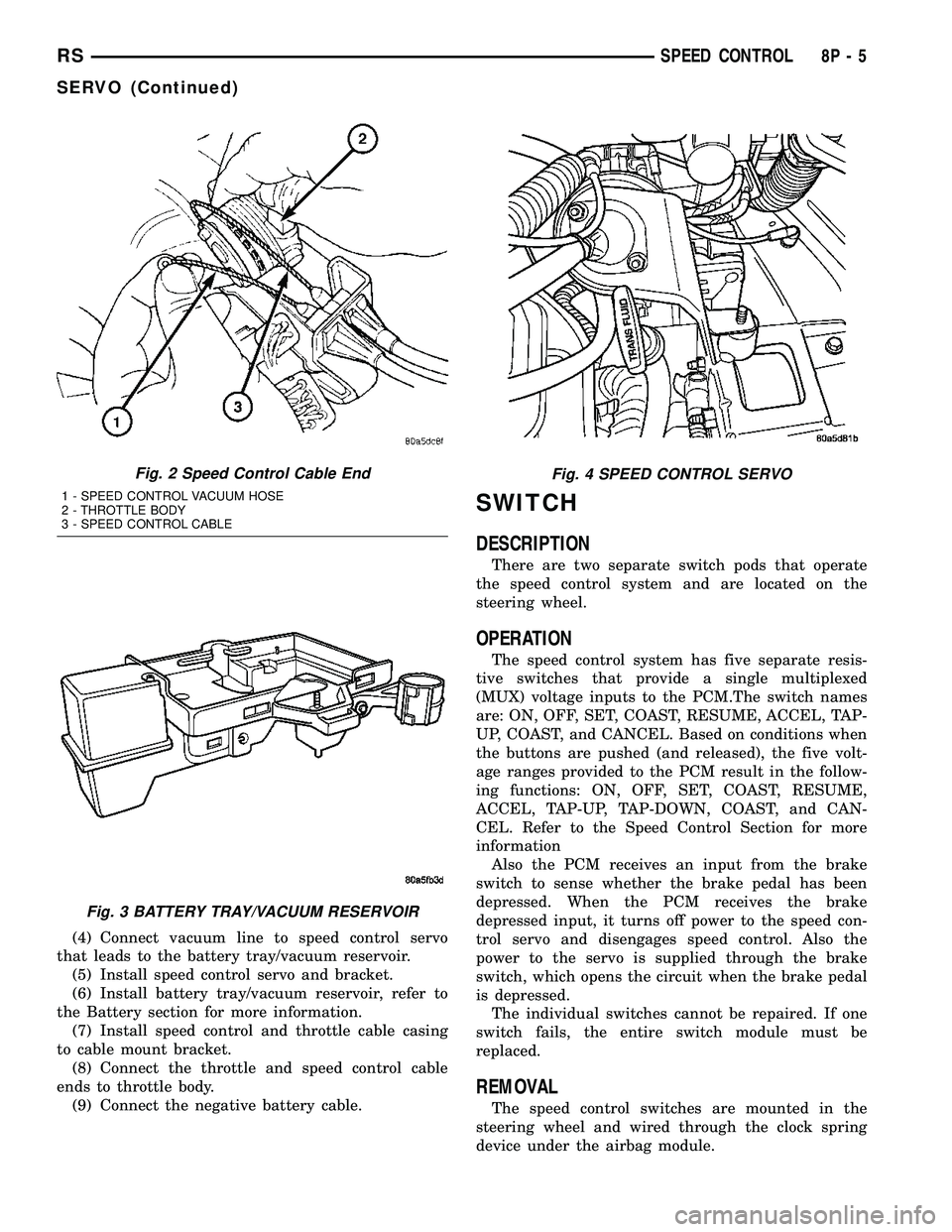
(4) Connect vacuum line to speed control servo
that leads to the battery tray/vacuum reservoir.
(5) Install speed control servo and bracket.
(6) Install battery tray/vacuum reservoir, refer to
the Battery section for more information.
(7) Install speed control and throttle cable casing
to cable mount bracket.
(8) Connect the throttle and speed control cable
ends to throttle body.
(9) Connect the negative battery cable.
SWITCH
DESCRIPTION
There are two separate switch pods that operate
the speed control system and are located on the
steering wheel.
OPERATION
The speed control system has five separate resis-
tive switches that provide a single multiplexed
(MUX) voltage inputs to the PCM.The switch names
are: ON, OFF, SET, COAST, RESUME, ACCEL, TAP-
UP, COAST, and CANCEL. Based on conditions when
the buttons are pushed (and released), the five volt-
age ranges provided to the PCM result in the follow-
ing functions: ON, OFF, SET, COAST, RESUME,
ACCEL, TAP-UP, TAP-DOWN, COAST, and CAN-
CEL. Refer to the Speed Control Section for more
information
Also the PCM receives an input from the brake
switch to sense whether the brake pedal has been
depressed. When the PCM receives the brake
depressed input, it turns off power to the speed con-
trol servo and disengages speed control. Also the
power to the servo is supplied through the brake
switch, which opens the circuit when the brake pedal
is depressed.
The individual switches cannot be repaired. If one
switch fails, the entire switch module must be
replaced.
REMOVAL
The speed control switches are mounted in the
steering wheel and wired through the clock spring
device under the airbag module.
Fig. 2 Speed Control Cable End
1 - SPEED CONTROL VACUUM HOSE
2 - THROTTLE BODY
3 - SPEED CONTROL CABLE
Fig. 3 BATTERY TRAY/VACUUM RESERVOIR
Fig. 4 SPEED CONTROL SERVO
RSSPEED CONTROL8P-5
SERVO (Continued)
Page 816 of 2339
8W-45 BODY CONTROL MODULE
Component Page
A/C-Heater Control............... 8W-45-16, 19
Auto Temp Control............... 8W-45-16, 19
Body Control Module . . . 8W-45-2, 3, 4, 5, 6, 7, 8, 9,
10, 11, 12, 13, 15, 16, 17, 18, 19, 20
Clockspring........................ 8W-45-17
Controller Antilock Brake............. 8W-45-13
Driver Door Courtesy Lamp........... 8W-45-15
Driver Door Lock Switch........... 8W-45-12, 15
Driver Heated Seat Module........... 8W-45-11
Floor Console Lamp................. 8W-45-13
Front Control Module................. 8W-45-3
Front Reading Lamps/Switch....... 8W-45-13, 15
Fuel Pump Module.................. 8W-45-15
Fuse 14............................ 8W-45-3
Fuse 19............................ 8W-45-2
Fuse 24............................ 8W-45-2
G301............................ 8W-45-2, 8
Headlamp Switch............. 8W-45-11, 16, 20
Hood Ajar Switch................... 8W-45-12
Ignition Switch...................... 8W-45-3
Instrument Cluster.......... 8W-45-2, 16, 18, 19
Instrument Panel Switch
Bank.................. 8W-45-10, 11, 17, 19
Integrated Power Module..... 8W-45-2, 3, 5, 6, 13
Left B-Pillar Switch.................. 8W-45-9
Left Cylinder Lock Switch............ 8W-45-10
Left Front Door Ajar Switch............ 8W-45-9
Left Front Door Lock Motor/Ajar
Switch........................ 8W-45-7, 9
Left Liftgate Flood Lamp............. 8W-45-12
Left Mid Reading Lamp............ 8W-45-9, 14
Left Power Mirror................... 8W-45-20
Left Rear Lamp Assembly........... 8W-45-5, 6
Left Rear Reading Lamp........... 8W-45-9, 14
Left Remote Radio Switch............ 8W-45-17
Left Repeater Lamp................. 8W-45-20
Left Sliding Door Control Module..... 8W-45-8, 10
Left Sliding Door Lock Motor........... 8W-45-7
Left Sliding Door Lock Motor/Ajar
Switch........................ 8W-45-7, 8
Left Visor/Vanity Lamp.............. 8W-45-13Component Page
License Lamp....................... 8W-45-8
Liftgate Ajar Switch................. 8W-45-12
Liftgate Cinch/Release Motor.......... 8W-45-12
Memory Set Switch.................. 8W-45-4
Message Center.................... 8W-45-18
Multi-Function Switch............... 8W-45-16
Overhead Console................. 8W-45-4, 11
Passenger Door Courtesy Lamp........ 8W-45-15
Passenger Door Lock Switch........ 8W-45-12, 15
Passenger Folding Mirror Relay........ 8W-45-20
Passenger Heated Seat Module........ 8W-45-11
Power Folding Mirror Switch.......... 8W-45-20
Power Liftgate Module............. 8W-45-8, 12
Radio............................ 8W-45-17
Rear Auto Temp Control Switch..... 8W-45-10, 19
Rear Blower Rear Control Switch....... 8W-45-10
Rear Dome Lamp.................... 8W-45-9
Rear View Mirror................... 8W-45-11
Rear Wiper Motor.................... 8W-45-8
Right B-Pillar Switch................. 8W-45-9
Right Cylinder Lock Switch........... 8W-45-10
Right Front Door Ajar Switch........... 8W-45-9
Right Front Door Lock Motor/Ajar
Switch........................ 8W-45-7, 9
Right Liftgate Flood Lamp............ 8W-45-12
Right Mid Reading Lamp........... 8W-45-9, 14
Right Power Mirror................. 8W-45-20
Right Rear Lamp Assembly.......... 8W-45-5, 6
Right Rear Reading Lamp.......... 8W-45-9, 14
Right Remote Radio Switch........... 8W-45-17
Right Repeater Lamp................ 8W-45-20
Right Sliding Door Control Module.... 8W-45-8, 10
Right Sliding Door Lock Motor.......... 8W-45-7
Right Sliding Door Lock Motor/Ajar
Switch........................ 8W-45-7, 8
Right Visor/Vanity Lamp............. 8W-45-13
Sentry Key Remote Entry Module....... 8W-45-3
Thatcham Alarm Module............. 8W-45-10
Traction Control Switch.............. 8W-45-17
Trailer Tow Connector................ 8W-45-5
RS8W-45 BODY CONTROL MODULE8W-45-1
Page 1244 of 2339
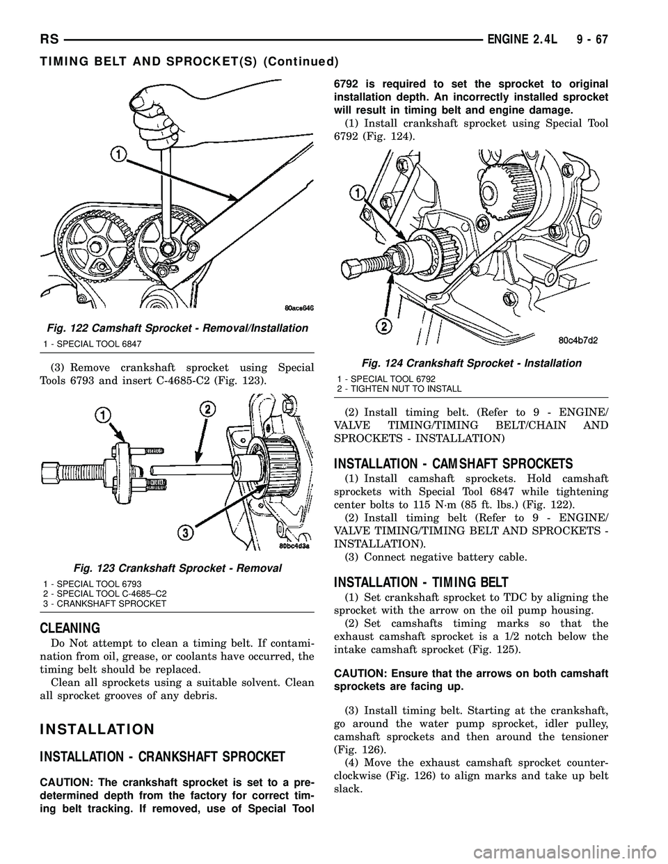
(3) Remove crankshaft sprocket using Special
Tools 6793 and insert C-4685-C2 (Fig. 123).
CLEANING
Do Not attempt to clean a timing belt. If contami-
nation from oil, grease, or coolants have occurred, the
timing belt should be replaced.
Clean all sprockets using a suitable solvent. Clean
all sprocket grooves of any debris.
INSTALLATION
INSTALLATION - CRANKSHAFT SPROCKET
CAUTION: The crankshaft sprocket is set to a pre-
determined depth from the factory for correct tim-
ing belt tracking. If removed, use of Special Tool6792 is required to set the sprocket to original
installation depth. An incorrectly installed sprocket
will result in timing belt and engine damage.
(1) Install crankshaft sprocket using Special Tool
6792 (Fig. 124).
(2) Install timing belt. (Refer to 9 - ENGINE/
VALVE TIMING/TIMING BELT/CHAIN AND
SPROCKETS - INSTALLATION)
INSTALLATION - CAMSHAFT SPROCKETS
(1) Install camshaft sprockets. Hold camshaft
sprockets with Special Tool 6847 while tightening
center bolts to 115 N´m (85 ft. lbs.) (Fig. 122).
(2) Install timing belt (Refer to 9 - ENGINE/
VALVE TIMING/TIMING BELT AND SPROCKETS -
INSTALLATION).
(3) Connect negative battery cable.
INSTALLATION - TIMING BELT
(1) Set crankshaft sprocket to TDC by aligning the
sprocket with the arrow on the oil pump housing.
(2) Set camshafts timing marks so that the
exhaust camshaft sprocket is a 1/2 notch below the
intake camshaft sprocket (Fig. 125).
CAUTION: Ensure that the arrows on both camshaft
sprockets are facing up.
(3) Install timing belt. Starting at the crankshaft,
go around the water pump sprocket, idler pulley,
camshaft sprockets and then around the tensioner
(Fig. 126).
(4) Move the exhaust camshaft sprocket counter-
clockwise (Fig. 126) to align marks and take up belt
slack.
Fig. 122 Camshaft Sprocket - Removal/Installation
1 - SPECIAL TOOL 6847
Fig. 123 Crankshaft Sprocket - Removal
1 - SPECIAL TOOL 6793
2 - SPECIAL TOOL C-4685±C2
3 - CRANKSHAFT SPROCKET
Fig. 124 Crankshaft Sprocket - Installation
1 - SPECIAL TOOL 6792
2 - TIGHTEN NUT TO INSTALL
RSENGINE 2.4L9-67
TIMING BELT AND SPROCKET(S) (Continued)
Page 1245 of 2339
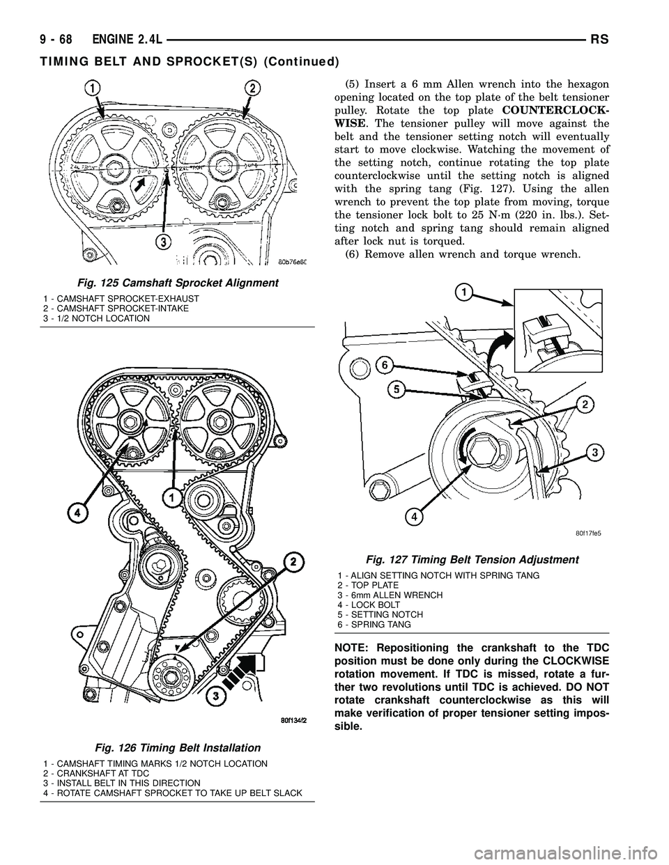
(5) Inserta6mmAllen wrench into the hexagon
opening located on the top plate of the belt tensioner
pulley. Rotate the top plateCOUNTERCLOCK-
WISE. The tensioner pulley will move against the
belt and the tensioner setting notch will eventually
start to move clockwise. Watching the movement of
the setting notch, continue rotating the top plate
counterclockwise until the setting notch is aligned
with the spring tang (Fig. 127). Using the allen
wrench to prevent the top plate from moving, torque
the tensioner lock bolt to 25 N´m (220 in. lbs.). Set-
ting notch and spring tang should remain aligned
after lock nut is torqued.
(6) Remove allen wrench and torque wrench.
NOTE: Repositioning the crankshaft to the TDC
position must be done only during the CLOCKWISE
rotation movement. If TDC is missed, rotate a fur-
ther two revolutions until TDC is achieved. DO NOT
rotate crankshaft counterclockwise as this will
make verification of proper tensioner setting impos-
sible.
Fig. 125 Camshaft Sprocket Alignment
1 - CAMSHAFT SPROCKET-EXHAUST
2 - CAMSHAFT SPROCKET-INTAKE
3 - 1/2 NOTCH LOCATION
Fig. 126 Timing Belt Installation
1 - CAMSHAFT TIMING MARKS 1/2 NOTCH LOCATION
2 - CRANKSHAFT AT TDC
3 - INSTALL BELT IN THIS DIRECTION
4 - ROTATE CAMSHAFT SPROCKET TO TAKE UP BELT SLACK
Fig. 127 Timing Belt Tension Adjustment
1 - ALIGN SETTING NOTCH WITH SPRING TANG
2 - TOP PLATE
3 - 6mm ALLEN WRENCH
4 - LOCK BOLT
5 - SETTING NOTCH
6 - SPRING TANG
9 - 68 ENGINE 2.4LRS
TIMING BELT AND SPROCKET(S) (Continued)
Page 1286 of 2339
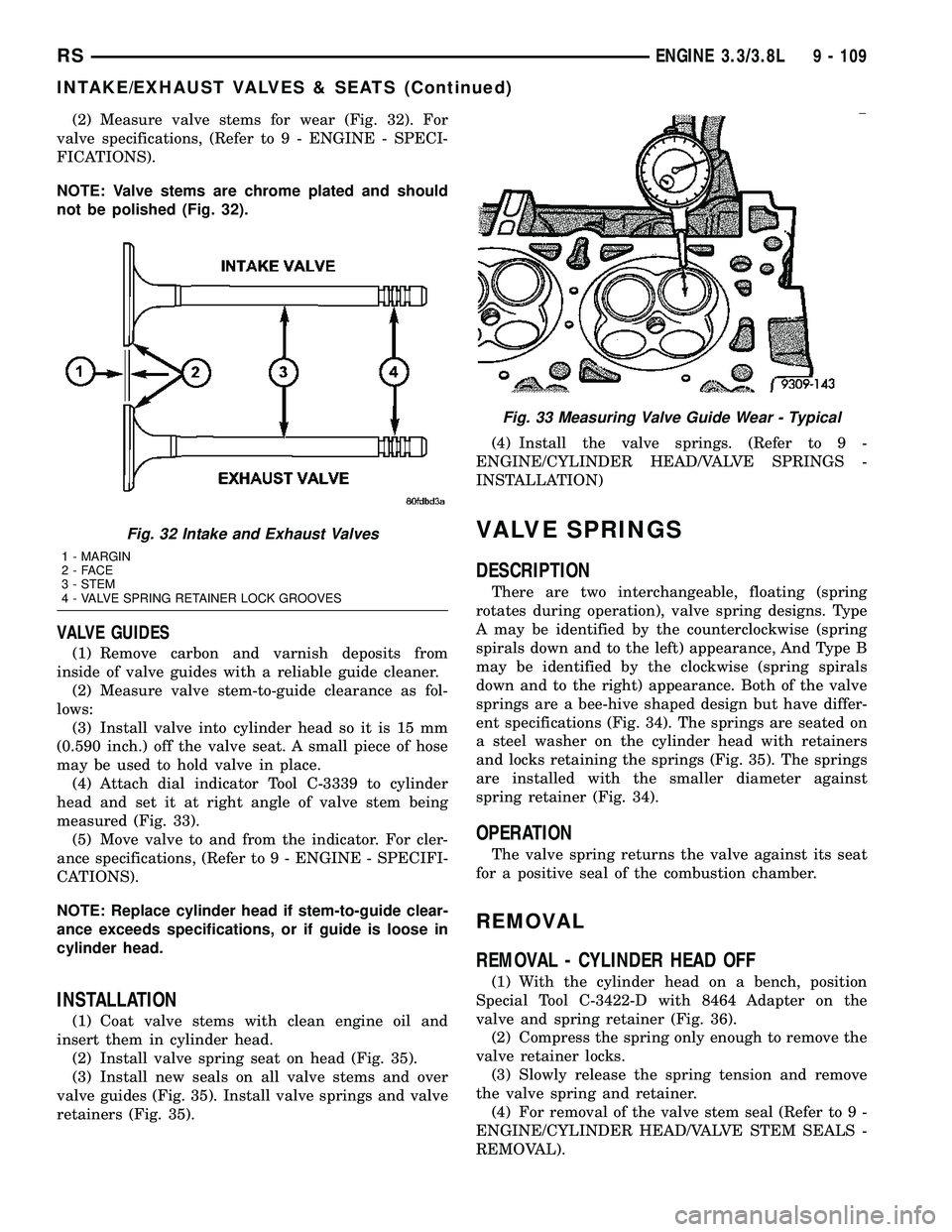
(2) Measure valve stems for wear (Fig. 32). For
valve specifications, (Refer to 9 - ENGINE - SPECI-
FICATIONS).
NOTE: Valve stems are chrome plated and should
not be polished (Fig. 32).
VALVE GUIDES
(1) Remove carbon and varnish deposits from
inside of valve guides with a reliable guide cleaner.
(2) Measure valve stem-to-guide clearance as fol-
lows:
(3) Install valve into cylinder head so it is 15 mm
(0.590 inch.) off the valve seat. A small piece of hose
may be used to hold valve in place.
(4) Attach dial indicator Tool C-3339 to cylinder
head and set it at right angle of valve stem being
measured (Fig. 33).
(5) Move valve to and from the indicator. For cler-
ance specifications, (Refer to 9 - ENGINE - SPECIFI-
CATIONS).
NOTE: Replace cylinder head if stem-to-guide clear-
ance exceeds specifications, or if guide is loose in
cylinder head.
INSTALLATION
(1) Coat valve stems with clean engine oil and
insert them in cylinder head.
(2) Install valve spring seat on head (Fig. 35).
(3) Install new seals on all valve stems and over
valve guides (Fig. 35). Install valve springs and valve
retainers (Fig. 35).(4) Install the valve springs. (Refer to 9 -
ENGINE/CYLINDER HEAD/VALVE SPRINGS -
INSTALLATION)
VALVE SPRINGS
DESCRIPTION
There are two interchangeable, floating (spring
rotates during operation), valve spring designs. Type
A may be identified by the counterclockwise (spring
spirals down and to the left) appearance, And Type B
may be identified by the clockwise (spring spirals
down and to the right) appearance. Both of the valve
springs are a bee-hive shaped design but have differ-
ent specifications (Fig. 34). The springs are seated on
a steel washer on the cylinder head with retainers
and locks retaining the springs (Fig. 35). The springs
are installed with the smaller diameter against
spring retainer (Fig. 34).
OPERATION
The valve spring returns the valve against its seat
for a positive seal of the combustion chamber.
REMOVAL
REMOVAL - CYLINDER HEAD OFF
(1) With the cylinder head on a bench, position
Special Tool C-3422-D with 8464 Adapter on the
valve and spring retainer (Fig. 36).
(2) Compress the spring only enough to remove the
valve retainer locks.
(3) Slowly release the spring tension and remove
the valve spring and retainer.
(4) For removal of the valve stem seal (Refer to 9 -
ENGINE/CYLINDER HEAD/VALVE STEM SEALS -
REMOVAL).
Fig. 32 Intake and Exhaust Valves
1 - MARGIN
2-FACE
3 - STEM
4 - VALVE SPRING RETAINER LOCK GROOVES
Fig. 33 Measuring Valve Guide Wear - Typical
RSENGINE 3.3/3.8L9 - 109
INTAKE/EXHAUST VALVES & SEATS (Continued)
Page 1288 of 2339
REMOVAL - CYLINDER HEAD ON
(1) Disconnect negative cable from battery.
(2) Remove spark plug wires and all spark plugs.
(3) Remove cylinder head cover(s). (Refer to 9 -
ENGINE/CYLINDER HEAD/CYLINDER HEAD
COVER(S) - REMOVAL)
(4) Remove rocker arms and shaft. (Refer to 9 -
ENGINE/CYLINDER HEAD/ROCKER ARMS -
REMOVAL)
(5) Rotate engine until the piston in the cylinder
bore requiring spring removal is at TDC.
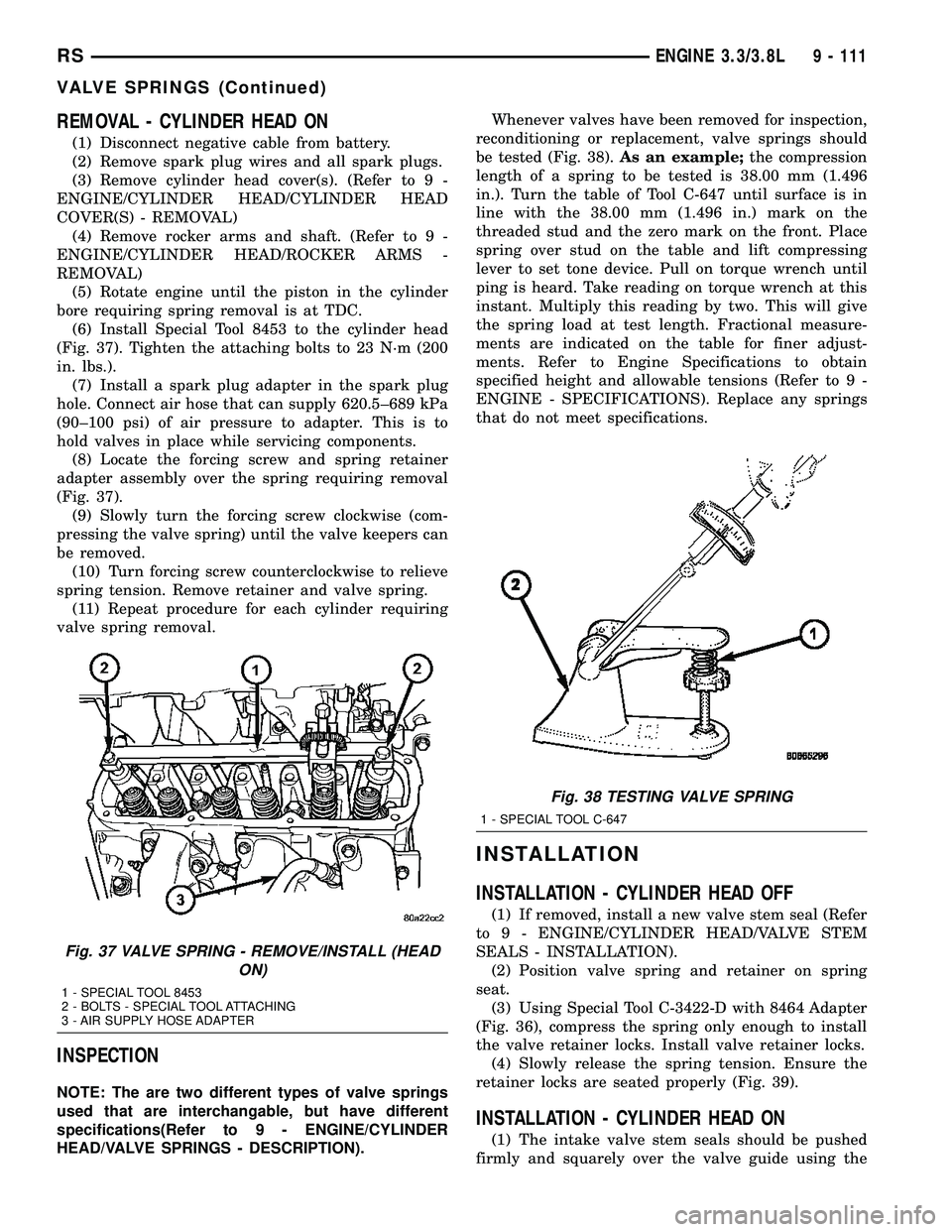
(6) Install Special Tool 8453 to the cylinder head
(Fig. 37). Tighten the attaching bolts to 23 N´m (200
in. lbs.).
(7) Install a spark plug adapter in the spark plug
hole. Connect air hose that can supply 620.5±689 kPa
(90±100 psi) of air pressure to adapter. This is to
hold valves in place while servicing components.
(8) Locate the forcing screw and spring retainer
adapter assembly over the spring requiring removal
(Fig. 37).
(9) Slowly turn the forcing screw clockwise (com-
pressing the valve spring) until the valve keepers can
be removed.
(10) Turn forcing screw counterclockwise to relieve
spring tension. Remove retainer and valve spring.
(11) Repeat procedure for each cylinder requiring
valve spring removal.
INSPECTION
NOTE: The are two different types of valve springs
used that are interchangable, but have different
specifications(Refer to 9 - ENGINE/CYLINDER
HEAD/VALVE SPRINGS - DESCRIPTION).Whenever valves have been removed for inspection,
reconditioning or replacement, valve springs should
be tested (Fig. 38).As an example;the compression
length of a spring to be tested is 38.00 mm (1.496
in.). Turn the table of Tool C-647 until surface is in
line with the 38.00 mm (1.496 in.) mark on the
threaded stud and the zero mark on the front. Place
spring over stud on the table and lift compressing
lever to set tone device. Pull on torque wrench until
ping is heard. Take reading on torque wrench at this
instant. Multiply this reading by two. This will give
the spring load at test length. Fractional measure-
ments are indicated on the table for finer adjust-
ments. Refer to Engine Specifications to obtain
specified height and allowable tensions (Refer to 9 -
ENGINE - SPECIFICATIONS). Replace any springs
that do not meet specifications.
INSTALLATION
INSTALLATION - CYLINDER HEAD OFF
(1) If removed, install a new valve stem seal (Refer
to 9 - ENGINE/CYLINDER HEAD/VALVE STEM
SEALS - INSTALLATION).
(2) Position valve spring and retainer on spring
seat.
(3) Using Special Tool C-3422-D with 8464 Adapter
(Fig. 36), compress the spring only enough to install
the valve retainer locks. Install valve retainer locks.
(4) Slowly release the spring tension. Ensure the
retainer locks are seated properly (Fig. 39).
INSTALLATION - CYLINDER HEAD ON
(1) The intake valve stem seals should be pushed
firmly and squarely over the valve guide using the
Fig. 37 VALVE SPRING - REMOVE/INSTALL (HEAD
ON)
1 - SPECIAL TOOL 8453
2 - BOLTS - SPECIAL TOOL ATTACHING
3 - AIR SUPPLY HOSE ADAPTER
Fig. 38 TESTING VALVE SPRING
1 - SPECIAL TOOL C-647
RSENGINE 3.3/3.8L9 - 111
VALVE SPRINGS (Continued)