radiator cap CHRYSLER VOYAGER 2005 User Guide
[x] Cancel search | Manufacturer: CHRYSLER, Model Year: 2005, Model line: VOYAGER, Model: CHRYSLER VOYAGER 2005Pages: 2339, PDF Size: 59.69 MB
Page 246 of 2339
INSTALLATION
(1)Be sure the air seal is in position before
radiator is installed.Slide radiator down into posi-
tion. Seat the radiator with the rubber isolators into
the mounting holes provided, with a 10 lbs. force.
(2) Position air conditioning condenser onto the
radiator lower mounts and ingage upper mounting
tabs. (Fig. 15).
(3) Install the radiator upper and lower hoses (Fig.
13) or (Fig. 14).
(4) Connect the coolant reserve/recovery hose.
(5) Connect the vapor purge solenoid to the mount-
ing bracket.
(6) Install the radiator fans. (Refer to 7 - COOL-
ING/ENGINE/RADIATOR FAN - INSTALLATION)
(7) Install the radiator upper crossmember sup-
port. (Refer to 23 - BODY/EXTERIOR/GRILLE
OPENING REINFORCEMENT - INSTALLATION)
(8) Fill the cooling system. (Refer to 7 - COOLING
- STANDARD PROCEDURE)
(9) Connect negative cable to battery.
RADIATOR DRAINCOCK
REMOVAL
NOTE: It is not necessary to remove draincock dur-
ing a routine coolant drain.
(1) Drain the cooling system. (Refer to 7 - COOL-
ING - STANDARD PROCEDURE)
(2) Using a screwdriver, open the draincock by
turning it counterclockwise until it stops.
(3) Pull the draincock from the radiator tank.
INSTALLATION
(1) Align draincock stem to radiator tank opening.
(2) Push draincock into the radiator tank opening.
CAUTION: Do not overtighten. The head of the
draincock may break off.
(3) Using a screwdriver, tighten the draincock by
turning clockwise until it stops.
(4) Fill the cooling system. (Refer to 7 - COOLING
- STANDARD PROCEDURE)
RADIATOR PRESSURE CAP
DESCRIPTION
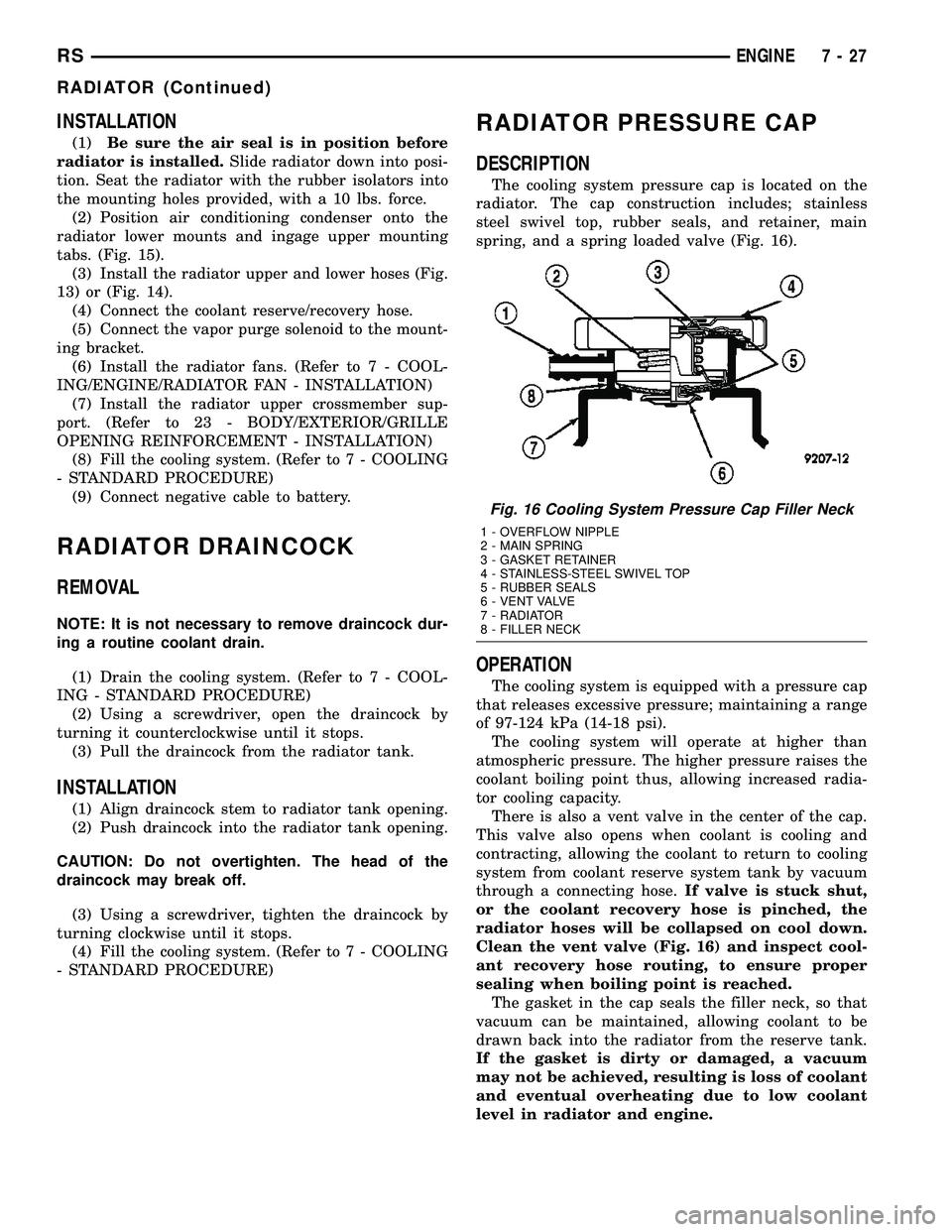
The cooling system pressure cap is located on the
radiator. The cap construction includes; stainless
steel swivel top, rubber seals, and retainer, main
spring, and a spring loaded valve (Fig. 16).
OPERATION
The cooling system is equipped with a pressure cap
that releases excessive pressure; maintaining a range
of 97-124 kPa (14-18 psi).
The cooling system will operate at higher than
atmospheric pressure. The higher pressure raises the
coolant boiling point thus, allowing increased radia-
tor cooling capacity.
There is also a vent valve in the center of the cap.
This valve also opens when coolant is cooling and
contracting, allowing the coolant to return to cooling
system from coolant reserve system tank by vacuum
through a connecting hose.If valve is stuck shut,
or the coolant recovery hose is pinched, the
radiator hoses will be collapsed on cool down.
Clean the vent valve (Fig. 16) and inspect cool-
ant recovery hose routing, to ensure proper
sealing when boiling point is reached.
The gasket in the cap seals the filler neck, so that
vacuum can be maintained, allowing coolant to be
drawn back into the radiator from the reserve tank.
If the gasket is dirty or damaged, a vacuum
may not be achieved, resulting is loss of coolant
and eventual overheating due to low coolant
level in radiator and engine.
Fig. 16 Cooling System Pressure Cap Filler Neck
1 - OVERFLOW NIPPLE
2 - MAIN SPRING
3 - GASKET RETAINER
4 - STAINLESS-STEEL SWIVEL TOP
5 - RUBBER SEALS
6 - VENT VALVE
7 - RADIATOR
8 - FILLER NECK
RSENGINE7-27
RADIATOR (Continued)
Page 247 of 2339
DIAGNOSIS AND TESTING
DIAGNOSIS AND TESTING - COOLING SYSTEM
PRESSURE CAP TESTING
Dip the pressure cap in water. Clean any deposits
off the vent valve or its seat and apply cap to end of
the Pressure Cap Test Adaptor that is included with
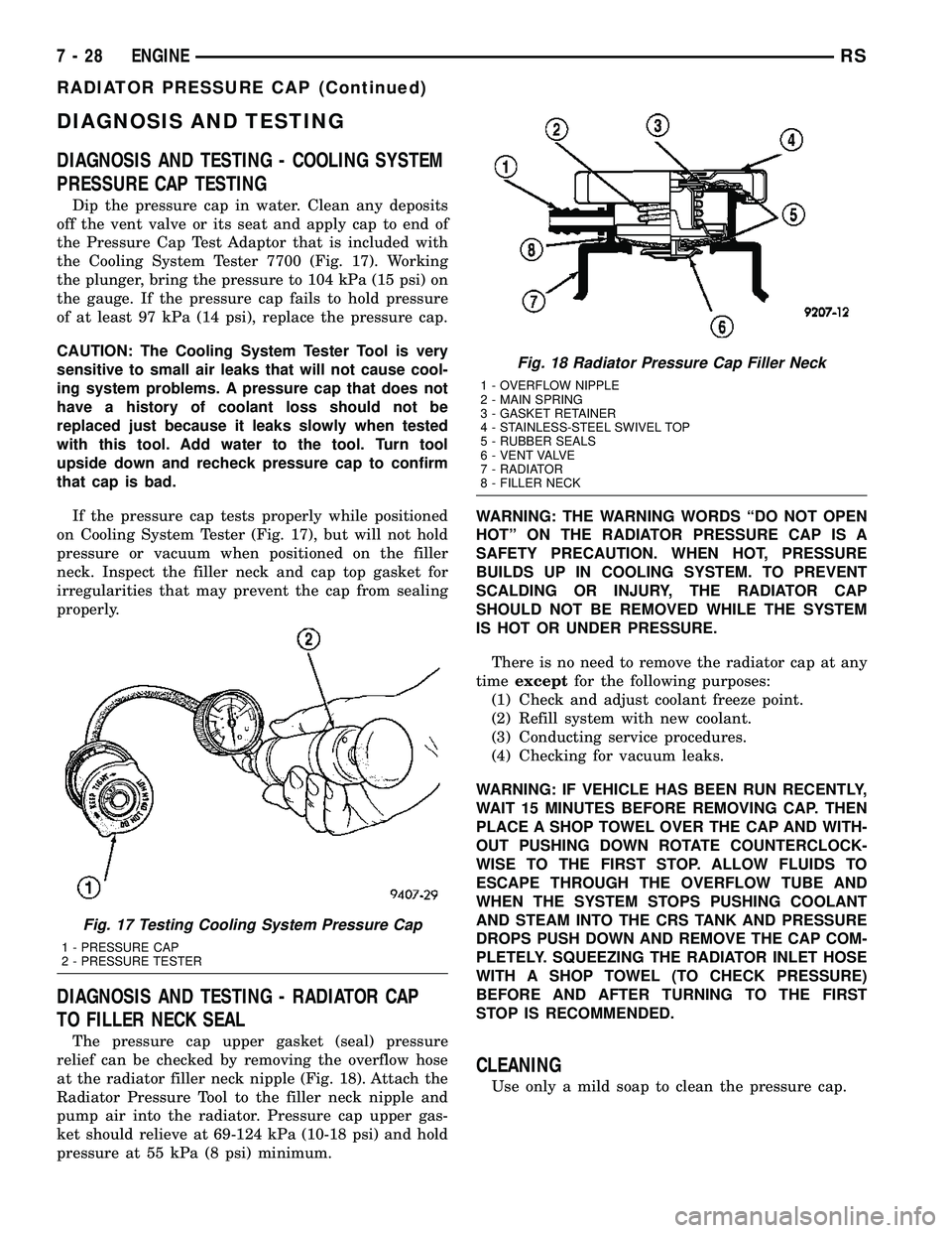
the Cooling System Tester 7700 (Fig. 17). Working
the plunger, bring the pressure to 104 kPa (15 psi) on
the gauge. If the pressure cap fails to hold pressure
of at least 97 kPa (14 psi), replace the pressure cap.
CAUTION: The Cooling System Tester Tool is very
sensitive to small air leaks that will not cause cool-
ing system problems. A pressure cap that does not
have a history of coolant loss should not be
replaced just because it leaks slowly when tested
with this tool. Add water to the tool. Turn tool
upside down and recheck pressure cap to confirm
that cap is bad.
If the pressure cap tests properly while positioned
on Cooling System Tester (Fig. 17), but will not hold
pressure or vacuum when positioned on the filler
neck. Inspect the filler neck and cap top gasket for
irregularities that may prevent the cap from sealing
properly.
DIAGNOSIS AND TESTING - RADIATOR CAP
TO FILLER NECK SEAL
The pressure cap upper gasket (seal) pressure
relief can be checked by removing the overflow hose
at the radiator filler neck nipple (Fig. 18). Attach the
Radiator Pressure Tool to the filler neck nipple and
pump air into the radiator. Pressure cap upper gas-
ket should relieve at 69-124 kPa (10-18 psi) and hold
pressure at 55 kPa (8 psi) minimum.WARNING: THE WARNING WORDS ªDO NOT OPEN
HOTº ON THE RADIATOR PRESSURE CAP IS A
SAFETY PRECAUTION. WHEN HOT, PRESSURE
BUILDS UP IN COOLING SYSTEM. TO PREVENT
SCALDING OR INJURY, THE RADIATOR CAP
SHOULD NOT BE REMOVED WHILE THE SYSTEM
IS HOT OR UNDER PRESSURE.
There is no need to remove the radiator cap at any
timeexceptfor the following purposes:
(1) Check and adjust coolant freeze point.
(2) Refill system with new coolant.
(3) Conducting service procedures.
(4) Checking for vacuum leaks.
WARNING: IF VEHICLE HAS BEEN RUN RECENTLY,
WAIT 15 MINUTES BEFORE REMOVING CAP. THEN
PLACE A SHOP TOWEL OVER THE CAP AND WITH-
OUT PUSHING DOWN ROTATE COUNTERCLOCK-
WISE TO THE FIRST STOP. ALLOW FLUIDS TO
ESCAPE THROUGH THE OVERFLOW TUBE AND
WHEN THE SYSTEM STOPS PUSHING COOLANT
AND STEAM INTO THE CRS TANK AND PRESSURE
DROPS PUSH DOWN AND REMOVE THE CAP COM-
PLETELY. SQUEEZING THE RADIATOR INLET HOSE
WITH A SHOP TOWEL (TO CHECK PRESSURE)
BEFORE AND AFTER TURNING TO THE FIRST
STOP IS RECOMMENDED.
CLEANING
Use only a mild soap to clean the pressure cap.
Fig. 17 Testing Cooling System Pressure Cap
1 - PRESSURE CAP
2 - PRESSURE TESTER
Fig. 18 Radiator Pressure Cap Filler Neck
1 - OVERFLOW NIPPLE
2 - MAIN SPRING
3 - GASKET RETAINER
4 - STAINLESS-STEEL SWIVEL TOP
5 - RUBBER SEALS
6 - VENT VALVE
7 - RADIATOR
8 - FILLER NECK
7 - 28 ENGINERS
RADIATOR PRESSURE CAP (Continued)
Page 248 of 2339
INSPECTION
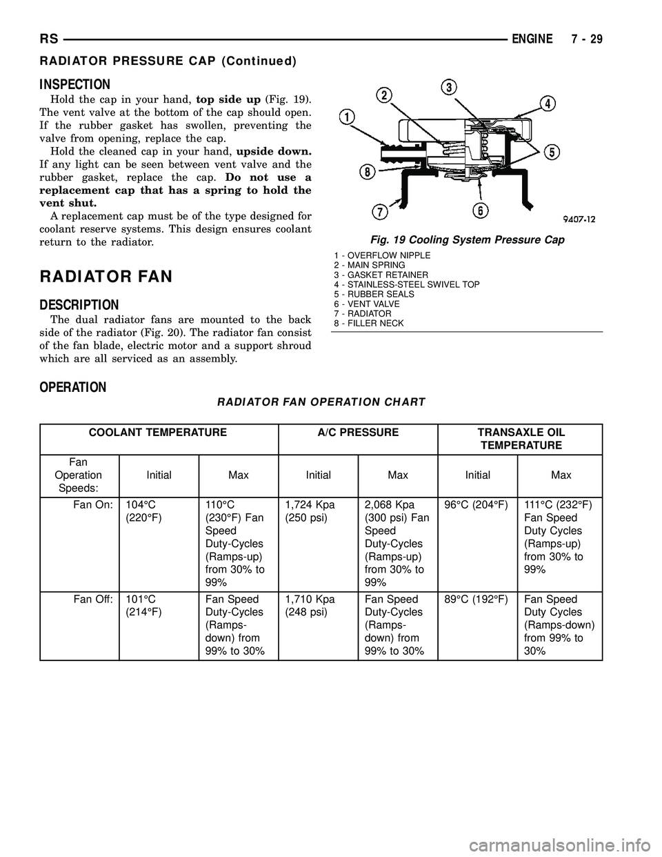
Hold the cap in your hand,top side up(Fig. 19).
The vent valve at the bottom of the cap should open.
If the rubber gasket has swollen, preventing the
valve from opening, replace the cap.
Hold the cleaned cap in your hand,upside down.
If any light can be seen between vent valve and the
rubber gasket, replace the cap.Do not use a
replacement cap that has a spring to hold the
vent shut.
A replacement cap must be of the type designed for
coolant reserve systems. This design ensures coolant
return to the radiator.
RADIATOR FAN
DESCRIPTION
The dual radiator fans are mounted to the back
side of the radiator (Fig. 20). The radiator fan consist
of the fan blade, electric motor and a support shroud
which are all serviced as an assembly.
OPERATION
RADIATOR FAN OPERATION CHART
COOLANT TEMPERATURE A/C PRESSURE TRANSAXLE OIL
TEMPERATURE
Fan
Operation
Speeds:Initial Max Initial Max Initial Max
Fan On: 104ÉC
(220ÉF)110ÉC
(230ÉF) Fan
Speed
Duty-Cycles
(Ramps-up)
from 30% to
99%1,724 Kpa
(250 psi)2,068 Kpa
(300 psi) Fan
Speed
Duty-Cycles
(Ramps-up)
from 30% to
99%96ÉC (204ÉF) 111ÉC (232ÉF)
Fan Speed
Duty Cycles
(Ramps-up)
from 30% to
99%
Fan Off: 101ÉC
(214ÉF)Fan Speed
Duty-Cycles
(Ramps-
down) from
99% to 30%1,710 Kpa
(248 psi)Fan Speed
Duty-Cycles
(Ramps-
down) from
99% to 30%89ÉC (192ÉF) Fan Speed
Duty Cycles
(Ramps-down)
from 99% to
30%
Fig. 19 Cooling System Pressure Cap
1 - OVERFLOW NIPPLE
2 - MAIN SPRING
3 - GASKET RETAINER
4 - STAINLESS-STEEL SWIVEL TOP
5 - RUBBER SEALS
6 - VENT VALVE
7 - RADIATOR
8 - FILLER NECK
RSENGINE7-29
RADIATOR PRESSURE CAP (Continued)
Page 258 of 2339
TRANSMISSION OIL COOLER
DESCRIPTION
The automatic transmission cooler is located in the
front of the radiator and behind the front fascia and
is conbined with the A/C condensor. The transmission
cooler is a heat exchanger that allows heat in the
transmission flud to be transferred to the air passing
over the cooler fins.
The Transmission oil cooler/A/C condenser assem-
blly is equipped with quick connect fitting for the
transmission oil cooler lines, a tapping block, for the
receiver/drier, and mounting provisions for the power
steering cooler.
The transmission oil cooler/AC condenser is ser-
viced as an assembly. For removal on vehicles
equipped with 2.4L/3.3L/3.8L engines, (Refer to 24 -
HEATING & AIR CONDITIONING/PLUMBING/A/C
CONDENSER - REMOVAL), vehicles equipped with2.5L/2.8L engines (Refer to 24 - HEATING & AIR
CONDITIONING/PLUMBING/A/C CONDENSER -
REMOVAL). For installation on vehicles equipped
with 2.4L/3.3L/3.8L engines (Refer to 24 - HEATING
& AIR CONDITIONING/PLUMBING/A/C CON-
DENSER - INSTALLATION), and vehicles equipped
with 2.5L/2.8L engines (Refer to 24 - HEATING &
AIR CONDITIONING/PLUMBING/A/C CON-
DENSER - INSTALLATION).
INSPECTION
Inspect all hoses, tubes, clamps and connections for
leaks, cracks, or damage. Replace as necessary. Use
only approved transmission oil cooler hoses that are
molded to fit the space available.
Inspect external coolers for leaks, loose mounts, or
damage. Replace as necessary.
TRANSMISSION OIL COOLER
LINES
REMOVAL
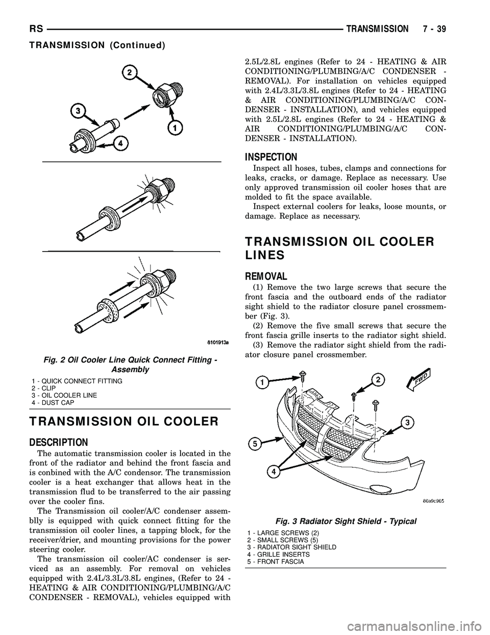
(1) Remove the two large screws that secure the
front fascia and the outboard ends of the radiator
sight shield to the radiator closure panel crossmem-
ber (Fig. 3).
(2) Remove the five small screws that secure the
front fascia grille inserts to the radiator sight shield.
(3) Remove the radiator sight shield from the radi-
ator closure panel crossmember.
Fig. 2 Oil Cooler Line Quick Connect Fitting -
Assembly
1 - QUICK CONNECT FITTING
2 - CLIP
3 - OIL COOLER LINE
4 - DUST CAP
Fig. 3 Radiator Sight Shield - Typical
1 - LARGE SCREWS (2)
2 - SMALL SCREWS (5)
3 - RADIATOR SIGHT SHIELD
4 - GRILLE INSERTS
5 - FRONT FASCIA
RSTRANSMISSION7-39
TRANSMISSION (Continued)
Page 507 of 2339

(3) Hoist vehicle.
(4) Disconnect electrical connector (Fig. 24).
(5) Remove the two screws attaching front impact
sensor to outer rails (Fig. 24).
(6) Remove sensor from vehicle.
SIDE IMPACT SENSORS
B-PILLAR MOUNTED
The right and left front row side impact sensors,
are mounted identically, on opposite sides of the vehi-
cle, in the b-pillar.
(1) Open hood, disconnect and isolate the battery
negative cable.
(2)
WARNING: Wait two minutes for the system reserve
capacitor to discharge before beginning any airbag
component service. Personal injury or death may
result.
(3) Remove the B-pillar lower trim for the side of
the vehicle that you are replacing the side impact
sensor (Refer to 23 - BODY/INTERIOR/B-PILLAR
LOWER TRIM - REMOVAL).
(4) Disconnect the electrical connector from the
impact sensor (Fig. 25).
(5) Remove the four retaining screws to the impact
sensor bracket (Fig. 25).
(6) Remove impact sensor from vehicle (Fig. 26).
SLIDING DOOR OPENING MOUNTED
The right and left second row side impact sensors,
are mounted identically, on opposite sides of the vehi-cle, in the sliding door opening lower rear where the
lower roller arm mounts in the lower door track.
(1) Open hood, disconnect and isolate the battery
negative cable.
(2)
Fig. 24 FRONT IMPACT SENSOR REMOVE/INSTALL
1 - FRONT IMPACT SENSOR WIRE HARNESS RETAINER
2 - FRONT IMPACT SENSOR RETAINING SCREW
3 - FRONT IMPACT SENSOR WIRE HARNESS
4 - FRONT IMPACT SENSOR
5 - LOWER RADIATOR SUPPORT
Fig. 25 FRONT ROW SIDE IMPACT SENSOR AND
BRACKET
1 - B-PILLAR
2 - FRONT ROW SIDE IMPACT SENSOR ELECTRICAL
CONNECTOR
3 - FRONT ROW SIDE IMPACT SENSOR AND MOUNTING
BRACKET
4 - FRONT ROW SIDE IMPACT SENSOR RETAINING SCREW
Fig. 26 FRONT ROW SIDE IMPACT SENSOR/
BRACKET
1 - FRONT ROW SIDE IMPACT SENSOR
2 - SENSOR TO BRACKET ATTACHMENT
3 - FRONT ROW SIDE IMPACT SENSOR MOUNTING BRACKET
8O - 20 RESTRAINTSRS
IMPACT SENSOR (Continued)
Page 516 of 2339

restraint system protection in case there is a loss of
battery current supply to the ORC during an impact.
Two sensors are contained within the ORC, an
electronic impact sensor and a safing sensor. The
ORC also monitors inputs from eight remote impact
sensors. Two front impact sensors are located on each
outboard side of the lower radiator support, and
three side impact sensors are located on each side of
the vehicle at the B-pillar, in the lower sliding door
opening in front of the C-pillar, and over the rear
wheel well between the C and D-pillars. The elec-
tronic impact sensors are accelerometers that sense
the rate of vehicle deceleration, which provides veri-
fication of the direction and severity of an impact.
The safing sensor is an electronic accelerometer
sensor within the ORC that provides an additional
logic input to the ORC microprocessor. The safing
sensor is used to verify the need for a supplemental
restraint deployment by detecting impact energy of a
lesser magnitude than that of the primary electronic
impact sensors, and must exceed a safing threshold
in order for the airbags to deploy. Vehicles equipped
with curtain airbags, there is a second safing sensor
within the ORC to provide confirmation to the ORC
microprocessor of side impact forces. This second saf-
ing sensor is a bi-directional unit that detects impact
forces from either side of the vehicle.
Pre-programmed decision algorithms in the ORC
microprocessor determine when the deceleration rate
as signaled by the impact sensors and the safing sen-
sors indicate an impact that is severe enough to
require supplemental restraint system protection
and, based upon the severity of the monitored
impact, determines the level of front airbag deploy-
ment force required for each front seating position.
When the programmed conditions are met, the ORC
sends the proper electrical signals to deploy the dual
multistage front airbags at the programmed force
levels, the front seat belt tensioners and, if the vehi-
cle is so equipped, either curtain airbag. For vehicles
equipped with the OCS, the passenger front airbag
and seat belt tensioner will be deployed by the ORC
only if enabled by the OCM messages (PAD indicator
OFF) at the time of the impact.
To diagnose and test the ORC and all airbag sys-
tem components, use a scan tool and the appropriate
diagnostic information.
REMOVAL
WARNING: Never replace both the Occupant
Restraint Controller (ORC) and the Occupant Clas-
sification Module (OCM) at the same time. If both
require replacement, replace one, then perform the
Airbag System test (Refer to 8 - ELECTRICAL/RE-
STRAINTS - DIAGNOSIS AND TESTING - AIRBAGSYSTEM) before replacing the other. Both the ORC
and the OCM store Occupant Classification System
(OCS) calibration data, which they transfer to one
another when one of them is replaced. If both are
replaced at the same time, an irreversible fault will
be set in both modules and the OCS may malfunc-
tion and result in personal injury or death.
(1) Disconnect and isolate the battery negative
cable.
(2)
WARNING: Wait two minutes for the airbag system
reserve capacitor to discharge before beginning
any airbag system or component service. Failure to
do so may result in accidental airbag deployment,
personal injury or death.
(3) Remove storage bin from instrument panel
(Refer to 23 - BODY/INSTRUMENT PANEL/STOR-
AGE BIN - REMOVAL).
(4) Remove three bolts holding ORC to floor
bracket (Fig. 39).
(5) Disconnect the wire connectors from the ORC
(Fig. 39).
(6) Remove the ORC from vehicle.
INSTALLATION
WARNING: Do not install ORC if mounting location
is deformed or damaged. This will cause the ORC
to be improperly located and could result in occu-
pant personal injury or death.
WARNING: Use correct screws when installing the
ORC.
Fig. 39 ORC - REMOVE/INSTALL
1 - ORC ELECTRICAL CONNECTORS
2 - ORC
3 - ORC MOUNTING SCREWS
RSRESTRAINTS8O-29
OCCUPANT RESTRAINT CONTROLLER (Continued)
Page 1189 of 2339
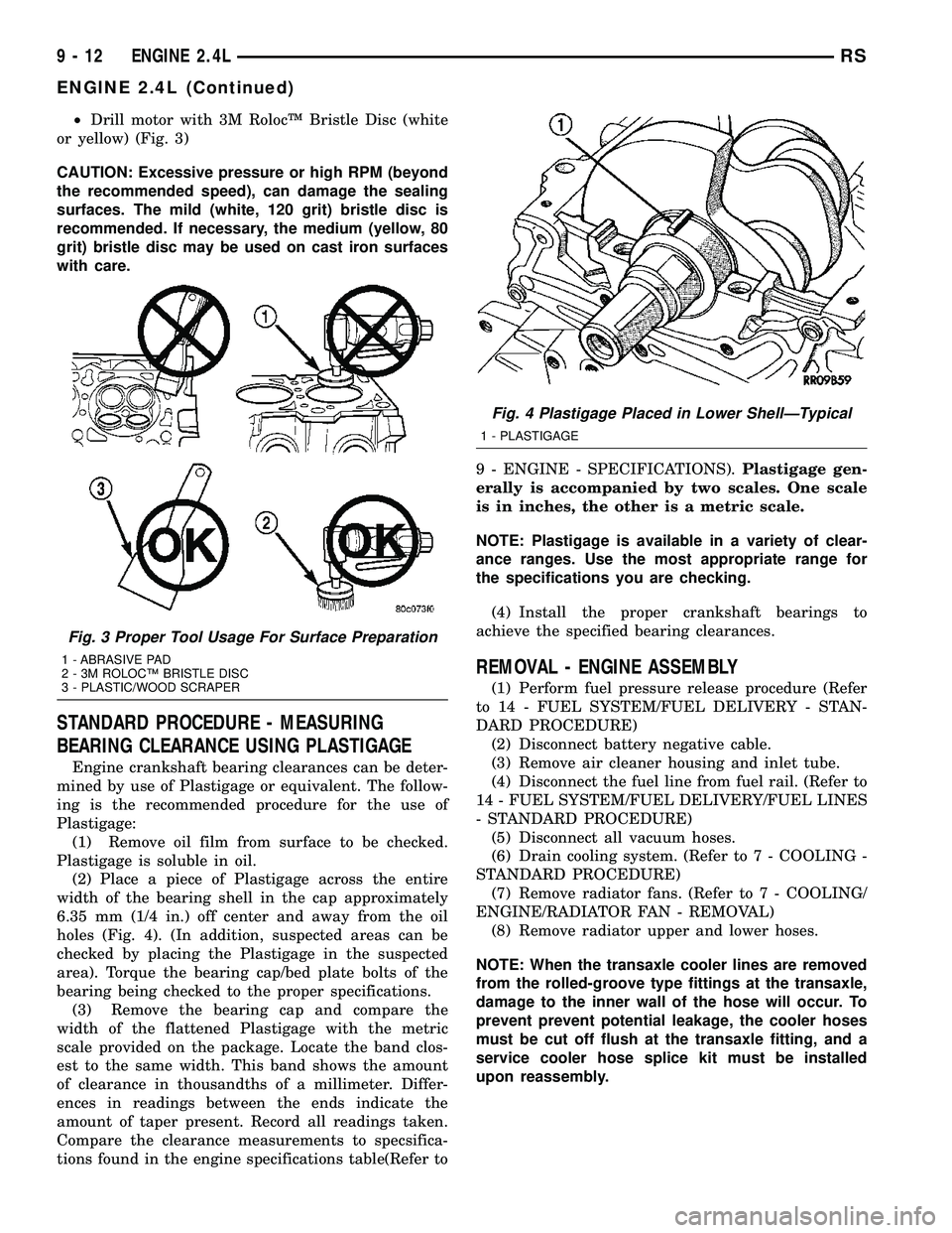
²Drill motor with 3M RolocŸ Bristle Disc (white
or yellow) (Fig. 3)
CAUTION: Excessive pressure or high RPM (beyond
the recommended speed), can damage the sealing
surfaces. The mild (white, 120 grit) bristle disc is
recommended. If necessary, the medium (yellow, 80
grit) bristle disc may be used on cast iron surfaces
with care.
STANDARD PROCEDURE - MEASURING
BEARING CLEARANCE USING PLASTIGAGE
Engine crankshaft bearing clearances can be deter-
mined by use of Plastigage or equivalent. The follow-
ing is the recommended procedure for the use of
Plastigage:
(1) Remove oil film from surface to be checked.
Plastigage is soluble in oil.
(2) Place a piece of Plastigage across the entire
width of the bearing shell in the cap approximately
6.35 mm (1/4 in.) off center and away from the oil
holes (Fig. 4). (In addition, suspected areas can be
checked by placing the Plastigage in the suspected
area). Torque the bearing cap/bed plate bolts of the
bearing being checked to the proper specifications.
(3) Remove the bearing cap and compare the
width of the flattened Plastigage with the metric
scale provided on the package. Locate the band clos-
est to the same width. This band shows the amount
of clearance in thousandths of a millimeter. Differ-
ences in readings between the ends indicate the
amount of taper present. Record all readings taken.
Compare the clearance measurements to specsifica-
tions found in the engine specifications table(Refer to9 - ENGINE - SPECIFICATIONS).Plastigage gen-
erally is accompanied by two scales. One scale
is in inches, the other is a metric scale.
NOTE: Plastigage is available in a variety of clear-
ance ranges. Use the most appropriate range for
the specifications you are checking.
(4) Install the proper crankshaft bearings to
achieve the specified bearing clearances.
REMOVAL - ENGINE ASSEMBLY
(1) Perform fuel pressure release procedure (Refer
to 14 - FUEL SYSTEM/FUEL DELIVERY - STAN-
DARD PROCEDURE)
(2) Disconnect battery negative cable.
(3) Remove air cleaner housing and inlet tube.
(4) Disconnect the fuel line from fuel rail. (Refer to
14 - FUEL SYSTEM/FUEL DELIVERY/FUEL LINES
- STANDARD PROCEDURE)
(5) Disconnect all vacuum hoses.
(6) Drain cooling system. (Refer to 7 - COOLING -
STANDARD PROCEDURE)
(7) Remove radiator fans. (Refer to 7 - COOLING/
ENGINE/RADIATOR FAN - REMOVAL)
(8) Remove radiator upper and lower hoses.
NOTE: When the transaxle cooler lines are removed
from the rolled-groove type fittings at the transaxle,
damage to the inner wall of the hose will occur. To
prevent prevent potential leakage, the cooler hoses
must be cut off flush at the transaxle fitting, and a
service cooler hose splice kit must be installed
upon reassembly.
Fig. 3 Proper Tool Usage For Surface Preparation
1 - ABRASIVE PAD
2 - 3M ROLOCŸ BRISTLE DISC
3 - PLASTIC/WOOD SCRAPER
Fig. 4 Plastigage Placed in Lower ShellÐTypical
1 - PLASTIGAGE
9 - 12 ENGINE 2.4LRS
ENGINE 2.4L (Continued)
Page 1202 of 2339
AIR CLEANER HOUSING
REMOVAL
(1) Disconnect the negative battery cable.
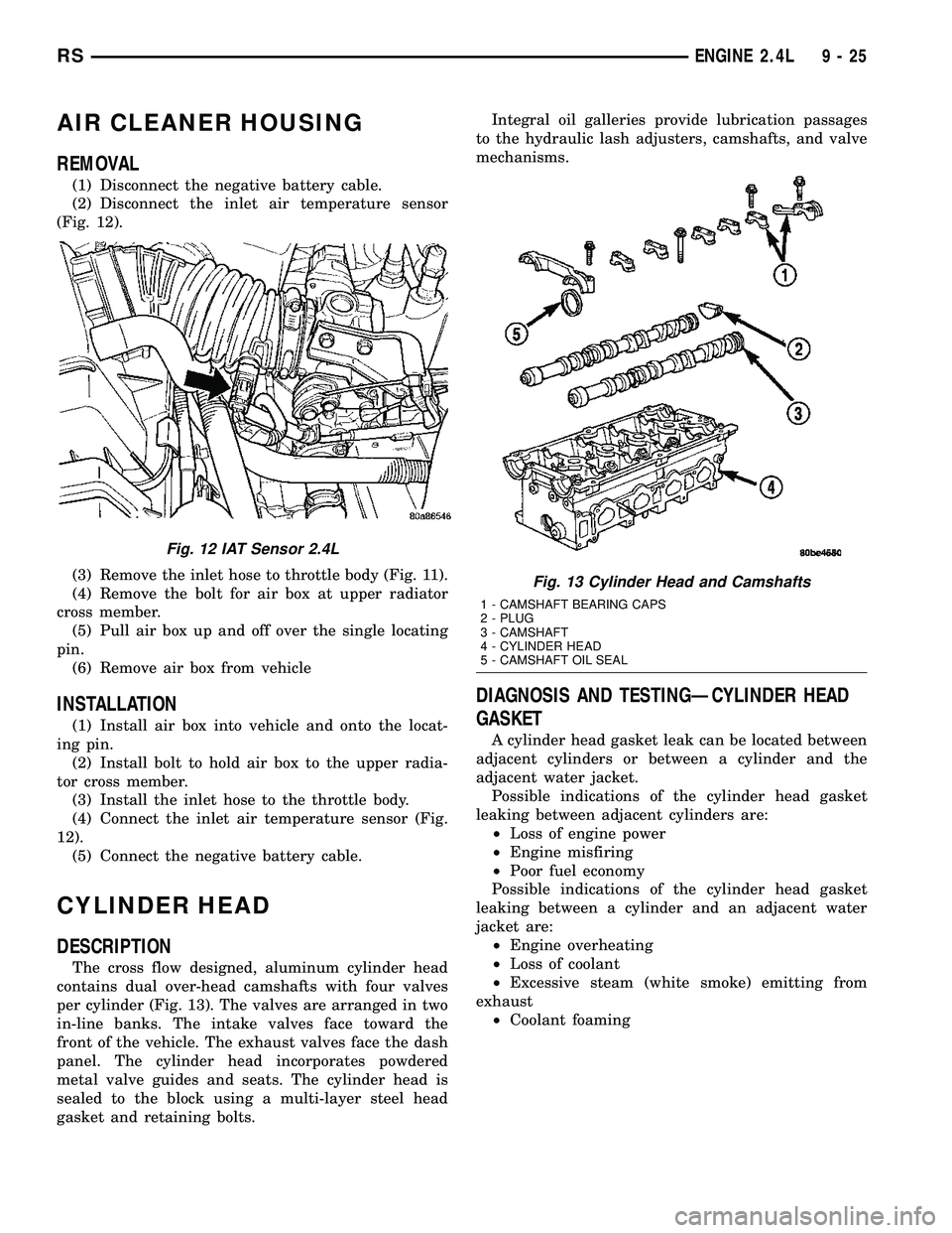
(2) Disconnect the inlet air temperature sensor
(Fig. 12).
(3) Remove the inlet hose to throttle body (Fig. 11).
(4) Remove the bolt for air box at upper radiator
cross member.
(5) Pull air box up and off over the single locating
pin.
(6) Remove air box from vehicle
INSTALLATION
(1) Install air box into vehicle and onto the locat-
ing pin.
(2) Install bolt to hold air box to the upper radia-
tor cross member.
(3) Install the inlet hose to the throttle body.
(4) Connect the inlet air temperature sensor (Fig.
12).
(5) Connect the negative battery cable.
CYLINDER HEAD
DESCRIPTION
The cross flow designed, aluminum cylinder head
contains dual over-head camshafts with four valves
per cylinder (Fig. 13). The valves are arranged in two
in-line banks. The intake valves face toward the
front of the vehicle. The exhaust valves face the dash
panel. The cylinder head incorporates powdered
metal valve guides and seats. The cylinder head is
sealed to the block using a multi-layer steel head
gasket and retaining bolts.Integral oil galleries provide lubrication passages
to the hydraulic lash adjusters, camshafts, and valve
mechanisms.
DIAGNOSIS AND TESTINGÐCYLINDER HEAD
GASKET
A cylinder head gasket leak can be located between
adjacent cylinders or between a cylinder and the
adjacent water jacket.
Possible indications of the cylinder head gasket
leaking between adjacent cylinders are:
²Loss of engine power
²Engine misfiring
²Poor fuel economy
Possible indications of the cylinder head gasket
leaking between a cylinder and an adjacent water
jacket are:
²Engine overheating
²Loss of coolant
²Excessive steam (white smoke) emitting from
exhaust
²Coolant foaming
Fig. 12 IAT Sensor 2.4L
Fig. 13 Cylinder Head and Camshafts
1 - CAMSHAFT BEARING CAPS
2 - PLUG
3 - CAMSHAFT
4 - CYLINDER HEAD
5 - CAMSHAFT OIL SEAL
RSENGINE 2.4L9-25
Page 1203 of 2339
CYLINDER-TO-CYLINDER LEAKAGE TEST
To determine if an engine cylinder head gasket is
leaking between adjacent cylinders, follow the proce-
dures in Cylinder Compression Pressure Test (Refer
to 9 - ENGINE - DIAGNOSIS AND TESTING). An
engine cylinder head gasket leaking between adja-
cent cylinders will result in approximately a 50±70%
reduction in compression pressure.
CYLINDER-TO-WATER JACKET LEAKAGE TEST
WARNING: USE EXTREME CAUTION WHEN THE
ENGINE IS OPERATING WITH COOLANT PRES-
SURE CAP REMOVED.
VISUAL TEST METHOD
With the engine cool, remove the coolant pressure
cap. Start the engine and allow it to warm up until
thermostat opens.
If a large combustion/compression pressure leak
exists, bubbles will be visible in the coolant.
COOLING SYSTEM TESTER METHOD
WARNING: WITH COOLING SYSTEM TESTER IN
PLACE, PRESSURE WILL BUILD UP FAST. EXCES-
SIVE PRESSURE BUILT UP, BY CONTINUOUS
ENGINE OPERATION, MUST BE RELEASED TO A
SAFE PRESSURE POINT. NEVER PERMIT PRES-
SURE TO EXCEED 138 kPa (20 psi).
Install Cooling System Tester 7700 or equivalent to
pressure cap neck. Start the engine and observe the
tester's pressure gauge. If gauge pulsates with every
power stroke of a cylinder a combustion pressure
leak is evident.
CHEMICAL TEST METHOD
Combustion leaks into the cooling system can also
be checked by using Bloc-Chek Kit C-3685-A or
equivalent. Perform test following the procedures
supplied with the tool kit.
REMOVAL - CYLINDER HEAD
(1) Perform fuel system pressure release procedure
before attempting any repairs.(Refer to 14 -
FUEL SYSTEM/FUEL DELIVERY - SPECIFICA-
TIONS)
(2) Disconnect battery negative cable.
(3) Drain cooling system. (Refer to 7 - COOLING -
STANDARD PROCEDURE)
(4) Remove air filter housing and inlet tube.
(5) Remove upper intake manifold. (Refer to 9 -
ENGINE/MANIFOLDS/INTAKE MANIFOLD -
REMOVAL)(6) Remove heater tube support bracket from cyl-
inder head.
(7) Disconnect radiator upper and heater supply
hoses from intake manifold water outlet connections.
(8) Remove accessory drive belts. (Refer to 7 -
COOLING/ACCESSORY DRIVE/DRIVE BELTS -
REMOVAL)
(9) Raise vehicle and remove exhaust pipe from
manifold.
(10) Remove power steering pump reservoir and
line support bracket from lower intake manifold and
set aside. Do not disconnect lines.
(11) Remove ignition coil and wires from engine.
(12) Disconnect cam sensor and fuel injector wir-
ing connectors.
(13) Remove timing belt and camshaft sprockets.
(Refer to 9 - ENGINE/VALVE TIMING/TIMING
BELT/CHAIN AND SPROCKETS - REMOVAL)
(14) Remove timing belt idler pulley and rear tim-
ing belt cover. (Refer to 9 - ENGINE/VALVE TIM-
ING/TIMING BELT / CHAIN COVER(S) -
REMOVAL)
(15) Remove cylinder head cover. (Refer to 9 -
ENGINE/CYLINDER HEAD/CYLINDER HEAD
COVER(S) - REMOVAL)
(16) Remove camshafts (Refer to 9 - ENGINE/
CYLINDER HEAD/CAMSHAFT(S) - REMOVAL).
NOTE: Identify rocker arm position to ensure cor-
rect re-installation in original position, if reused.
(17) Remove rocker arms. (Refer to 9 - ENGINE/
CYLINDER HEAD/ROCKER ARMS - REMOVAL)
(18) Remove cylinder head bolts in REVERSE
sequence of tightening (Fig. 19).
(19) Remove cylinder head from engine block.
(20) Inspect and clean cylinder head. (Refer to 9 -
ENGINE/CYLINDER HEAD - INSPECTION) (Refer
to 9 - ENGINE/CYLINDER HEAD - CLEANING)
CLEANING
To ensure engine gasket sealing, proper surface
preparation must be performed, especially with the
use of aluminum engine components and multi-layer
steel cylinder head gaskets.
NOTE: Multi-Layer Steel (MLS) head gaskets require
a scratch free sealing surface.
Remove all gasket material from cylinder head and
block (Refer to 9 - ENGINE - STANDARD PROCE-
DURE). Be careful not to gouge or scratch the alumi-
num head sealing surface.
Clean all engine oil passages.
9 - 26 ENGINE 2.4LRS
CYLINDER HEAD (Continued)
Page 1265 of 2339
(3) Place a shop towel around the spark plugs
when removing them from the engine. This will catch
any fluid that may possibly be in the cylinder under
pressure.
(4) With all spark plugs removed, rotate engine
crankshaft using a breaker bar and socket.
(5) Identify the fluid in the cylinder(s) (i.e., cool-
ant, fuel, oil or other).
(6) Make sure all fluid has been removed from the
cylinders. Inspect engine for damage (i.e., connecting
rods, pistons, valves, etc.)
(7) Repair engine or components as necessary to
prevent this problem from re-occurring.
CAUTION: Squirt approximately one teaspoon of oil
into the cylinders, rotate engine to lubricate the cyl-
inder walls to prevent damage on restart.
(8) Install new spark plugs.
(9) Drain engine oil and remove oil filter.
(10) Install a new oil filter.
(11) Fill engine with specified amount of approved
oil.
(12) Connect negative battery cable.
(13) Start engine and check for any leaks.
STANDARD PROCEDURE - REPAIR OF
DAMAGED OR WORN THREADS
Damaged or worn threads (excluding spark plug
and camshaft bearing cap attaching threads) can be
repaired. Essentially, this repair consists of drilling
out worn or damaged threads, tapping the hole with
a special Heli-Coil Tap, (or equivalent) and installing
an insert into the tapped hole. This brings the hole
back to its original thread size.
CAUTION: Be sure that the tapped holes maintain
the original center line.
Heli-Coil tools and inserts are readily available
from automotive parts jobbers.
STANDARD PROCEDURE - ENGINE CORE AND
OIL GALLERY PLUGS
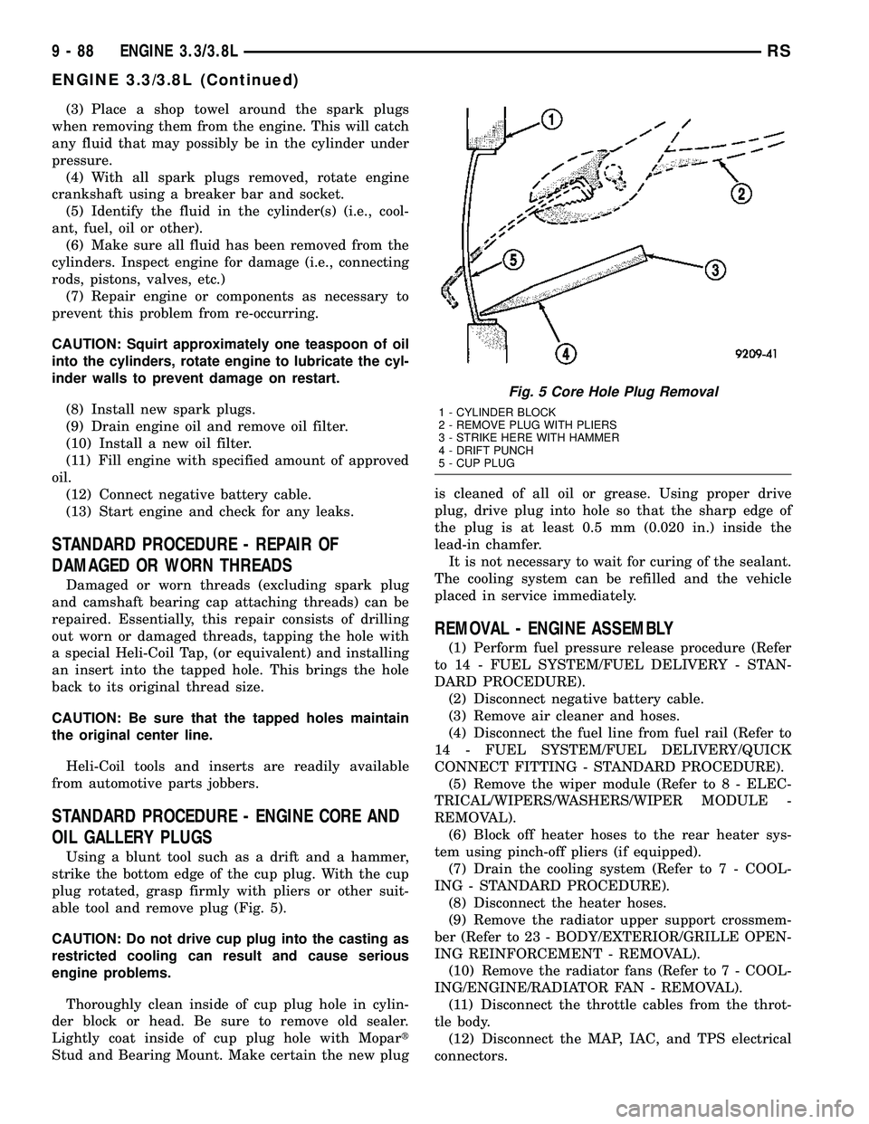
Using a blunt tool such as a drift and a hammer,
strike the bottom edge of the cup plug. With the cup
plug rotated, grasp firmly with pliers or other suit-
able tool and remove plug (Fig. 5).
CAUTION: Do not drive cup plug into the casting as
restricted cooling can result and cause serious
engine problems.
Thoroughly clean inside of cup plug hole in cylin-
der block or head. Be sure to remove old sealer.
Lightly coat inside of cup plug hole with Mopart
Stud and Bearing Mount. Make certain the new plugis cleaned of all oil or grease. Using proper drive
plug, drive plug into hole so that the sharp edge of
the plug is at least 0.5 mm (0.020 in.) inside the
lead-in chamfer.
It is not necessary to wait for curing of the sealant.
The cooling system can be refilled and the vehicle
placed in service immediately.
REMOVAL - ENGINE ASSEMBLY
(1) Perform fuel pressure release procedure (Refer
to 14 - FUEL SYSTEM/FUEL DELIVERY - STAN-
DARD PROCEDURE).
(2) Disconnect negative battery cable.
(3) Remove air cleaner and hoses.
(4) Disconnect the fuel line from fuel rail (Refer to
14 - FUEL SYSTEM/FUEL DELIVERY/QUICK
CONNECT FITTING - STANDARD PROCEDURE).
(5) Remove the wiper module (Refer to 8 - ELEC-
TRICAL/WIPERS/WASHERS/WIPER MODULE -
REMOVAL).
(6) Block off heater hoses to the rear heater sys-
tem using pinch-off pliers (if equipped).
(7) Drain the cooling system (Refer to 7 - COOL-
ING - STANDARD PROCEDURE).
(8) Disconnect the heater hoses.
(9) Remove the radiator upper support crossmem-
ber (Refer to 23 - BODY/EXTERIOR/GRILLE OPEN-
ING REINFORCEMENT - REMOVAL).
(10) Remove the radiator fans (Refer to 7 - COOL-
ING/ENGINE/RADIATOR FAN - REMOVAL).
(11) Disconnect the throttle cables from the throt-
tle body.
(12) Disconnect the MAP, IAC, and TPS electrical
connectors.
Fig. 5 Core Hole Plug Removal
1 - CYLINDER BLOCK
2 - REMOVE PLUG WITH PLIERS
3 - STRIKE HERE WITH HAMMER
4 - DRIFT PUNCH
5 - CUP PLUG
9 - 88 ENGINE 3.3/3.8LRS
ENGINE 3.3/3.8L (Continued)