radiator cap CHRYSLER VOYAGER 2005 Owner's Manual
[x] Cancel search | Manufacturer: CHRYSLER, Model Year: 2005, Model line: VOYAGER, Model: CHRYSLER VOYAGER 2005Pages: 2339, PDF Size: 59.69 MB
Page 1279 of 2339
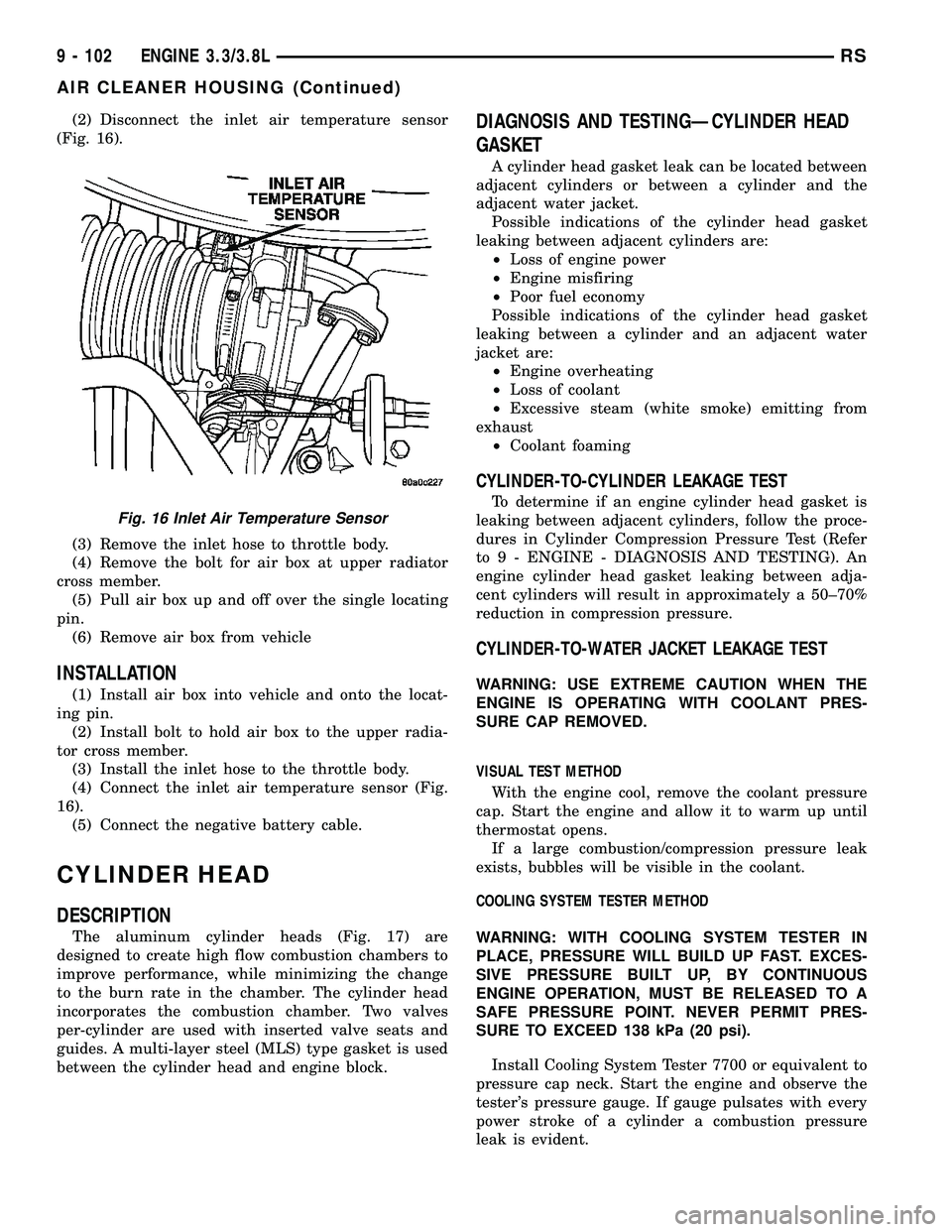
(2) Disconnect the inlet air temperature sensor
(Fig. 16).
(3) Remove the inlet hose to throttle body.
(4) Remove the bolt for air box at upper radiator
cross member.
(5) Pull air box up and off over the single locating
pin.
(6) Remove air box from vehicle
INSTALLATION
(1) Install air box into vehicle and onto the locat-
ing pin.
(2) Install bolt to hold air box to the upper radia-
tor cross member.
(3) Install the inlet hose to the throttle body.
(4) Connect the inlet air temperature sensor (Fig.
16).
(5) Connect the negative battery cable.
CYLINDER HEAD
DESCRIPTION
The aluminum cylinder heads (Fig. 17) are
designed to create high flow combustion chambers to
improve performance, while minimizing the change
to the burn rate in the chamber. The cylinder head
incorporates the combustion chamber. Two valves
per-cylinder are used with inserted valve seats and
guides. A multi-layer steel (MLS) type gasket is used
between the cylinder head and engine block.
DIAGNOSIS AND TESTINGÐCYLINDER HEAD
GASKET
A cylinder head gasket leak can be located between
adjacent cylinders or between a cylinder and the
adjacent water jacket.
Possible indications of the cylinder head gasket
leaking between adjacent cylinders are:
²Loss of engine power
²Engine misfiring
²Poor fuel economy
Possible indications of the cylinder head gasket
leaking between a cylinder and an adjacent water
jacket are:
²Engine overheating
²Loss of coolant
²Excessive steam (white smoke) emitting from
exhaust
²Coolant foaming
CYLINDER-TO-CYLINDER LEAKAGE TEST
To determine if an engine cylinder head gasket is
leaking between adjacent cylinders, follow the proce-
dures in Cylinder Compression Pressure Test (Refer
to 9 - ENGINE - DIAGNOSIS AND TESTING). An
engine cylinder head gasket leaking between adja-
cent cylinders will result in approximately a 50±70%
reduction in compression pressure.
CYLINDER-TO-WATER JACKET LEAKAGE TEST
WARNING: USE EXTREME CAUTION WHEN THE
ENGINE IS OPERATING WITH COOLANT PRES-
SURE CAP REMOVED.
VISUAL TEST METHOD
With the engine cool, remove the coolant pressure
cap. Start the engine and allow it to warm up until
thermostat opens.
If a large combustion/compression pressure leak
exists, bubbles will be visible in the coolant.
COOLING SYSTEM TESTER METHOD
WARNING: WITH COOLING SYSTEM TESTER IN
PLACE, PRESSURE WILL BUILD UP FAST. EXCES-
SIVE PRESSURE BUILT UP, BY CONTINUOUS
ENGINE OPERATION, MUST BE RELEASED TO A
SAFE PRESSURE POINT. NEVER PERMIT PRES-
SURE TO EXCEED 138 kPa (20 psi).
Install Cooling System Tester 7700 or equivalent to
pressure cap neck. Start the engine and observe the
tester's pressure gauge. If gauge pulsates with every
power stroke of a cylinder a combustion pressure
leak is evident.
Fig. 16 Inlet Air Temperature Sensor
9 - 102 ENGINE 3.3/3.8LRS
AIR CLEANER HOUSING (Continued)
Page 1317 of 2339
(11) Start engine and inspect for leaks.
(12) Stop engine and inspect oil level.
NOTE: Care should be exercised when disposing
used engine oil after it has been drained from a
vehicle engine. Refer to the WARNING listed above.
STANDARD PROCEDURE - ENGINE OIL LEVEL
CHECK
The best time to check engine oil level is after it
has sat overnight, or if the engine has been running,
allow the engine to be shut off for at least 5 minutes
before checking oil level.
Checking the oil while the vehicle is on level
ground will improve the accuracy of the oil level
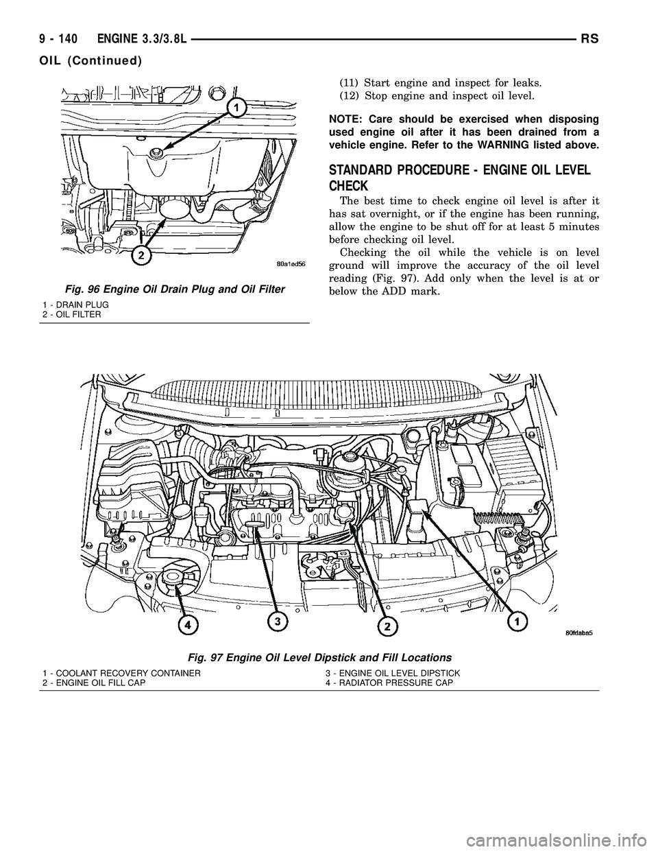
reading (Fig. 97). Add only when the level is at or
below the ADD mark.
Fig. 97 Engine Oil Level Dipstick and Fill Locations
1 - COOLANT RECOVERY CONTAINER 3 - ENGINE OIL LEVEL DIPSTICK
2 - ENGINE OIL FILL CAP 4 - RADIATOR PRESSURE CAP
Fig. 96 Engine Oil Drain Plug and Oil Filter
1 - DRAIN PLUG
2 - OIL FILTER
9 - 140 ENGINE 3.3/3.8LRS
OIL (Continued)
Page 1333 of 2339

(4) Apply force in the reverse direction to the fol-
lowing torque:
²41 N´m (30 ft. lb.) with cylinder heads installed
²20 N´m (15 ft. lb.) with cylinder heads removed
(5) Measure amount of sprocket/chain movement.
(6) Install a new timing chain and sprockets if
movement exceeds 3.175 mm (1/8 in.).
TIMING CHAIN COVER
REMOVAL
(1) Disconnect negative cable from battery.
(2) Drain cooling system. (Refer to 7 - COOLING -
STANDARD PROCEDURE)
(3) Raise vehicle on hoist.
(4) Drain engine oil.
(5) Remove right wheel and inner splash shield.
(6) Remove oil pan. (Refer to 9 - ENGINE/LUBRI-
CATION/OIL PAN - REMOVAL)
(7) Remove oil pick-up tube (Fig. 134).
(8) Remove accessory drive belt. (Refer to 7 -
COOLING/ACCESSORY DRIVE/DRIVE BELTS -
REMOVAL)
(9) Remove A/C compressor and set aside.
(10) Remove crankshaft vibration damper. (Refer
to 9 - ENGINE/ENGINE BLOCK/VIBRATION
DAMPER - REMOVAL)
(11) Remove radiator lower hose.
(12) Remove heater hose from timing chain cover
housing (Fig. 135) or water pump inlet tube (if
engine oil cooler equipped) (Fig. 136).
(13) Remove the right side engine mount. (Refer to
9 - ENGINE/ENGINE MOUNTING/RIGHT MOUNT
- REMOVAL)
(14) Remove idler pulley from engine bracket (Fig.
137).
(15) Remove the engine mount bracket (Fig. 137).(16) Remove camshaft position sensor from timing
chain cover (Fig. 137).
Fig. 133 Measuring Timing Chain Wear
1 - TORQUE WRENCH
Fig. 134 OIL PICKUP TUBE
1 - BOLT
2 - OIL PICK-UP TUBE
3 - O-RING
Fig. 135 HEATER RETURN HOSE (Without Engine
Oil Cooler)
1 - CAP AND CLAMP (OIL COOLER EQUIPPED ONLY)
2 - HOSE ASSEMBLY - HEATER RETURN
3 - BOLT - HEATER TUBE ATTACHING
4 - BOLT - HEATER TUBE ATTACHING
9 - 156 ENGINE 3.3/3.8LRS
VALVE TIMING (Continued)
Page 2152 of 2339
HEATING & AIR CONDITIONING
TABLE OF CONTENTS
page page
HEATING & AIR CONDITIONING
DESCRIPTION
ENGINE COOLING SYSTEM
REQUIREMENTS.......................1
HEATER AND AIR CONDITIONER..........1
MANUAL SINGLE ZONE.................2
MANUAL DUAL ZONE...................2
MANUAL THREE ZONE..................2
AUTOMATIC TEMPERATURE CONTROL....3
OPERATION
HEATER AND AIR CONDITIONER..........4
MANUAL SINGLE ZONE.................4
MANUAL DUAL ZONE...................5
MANUAL THREE ZONE..................5AUTOMATIC TEMPERATURE CONTROL....5
DIAGNOSIS AND TESTING
A/C COOL DOWN TEST.................6
A/C PERFORMANCE TEST...............7
HEATER PERFORMANCE TEST..........10
SPECIFICATIONS
A/C SYSTEM.........................11
CONTROLS - FRONT.....................13
CONTROLS - REAR......................33
DISTRIBUTION - FRONT...................42
DISTRIBUTION - REAR....................56
PLUMBING - FRONT.....................64
PLUMBING - REAR......................98
CABIN HEATER........................113
HEATING & AIR
CONDITIONING
DESCRIPTION
ENGINE COOLING SYSTEM REQUIREMENTS
To maintain the performance level of the heating,
ventilation and air conditioning (HVAC) system, the
engine cooling system must be properly maintained.
The use of a bug screen is not recommended. Any
obstructions in front of the radiator or condenser will
reduce the performance of the air conditioning and
engine cooling systems.
The engine cooling system includes the radiator,
thermostat, radiator hoses and the engine coolant
pump. Refer to Cooling for more information before
opening or attempting any service to the engine cool-
ing system.
HEATER AND AIR CONDITIONER
A manually controlled single zone type heating-air
conditioning system, manually controlled dual zone
type heating-air conditioning system, manually con-
trolled three zone type heating-air conditioning sys-
tem or an automatic controlled three zone type
heating-air conditioning system is available on this
model.
All vehicles are equipped with a common heater,
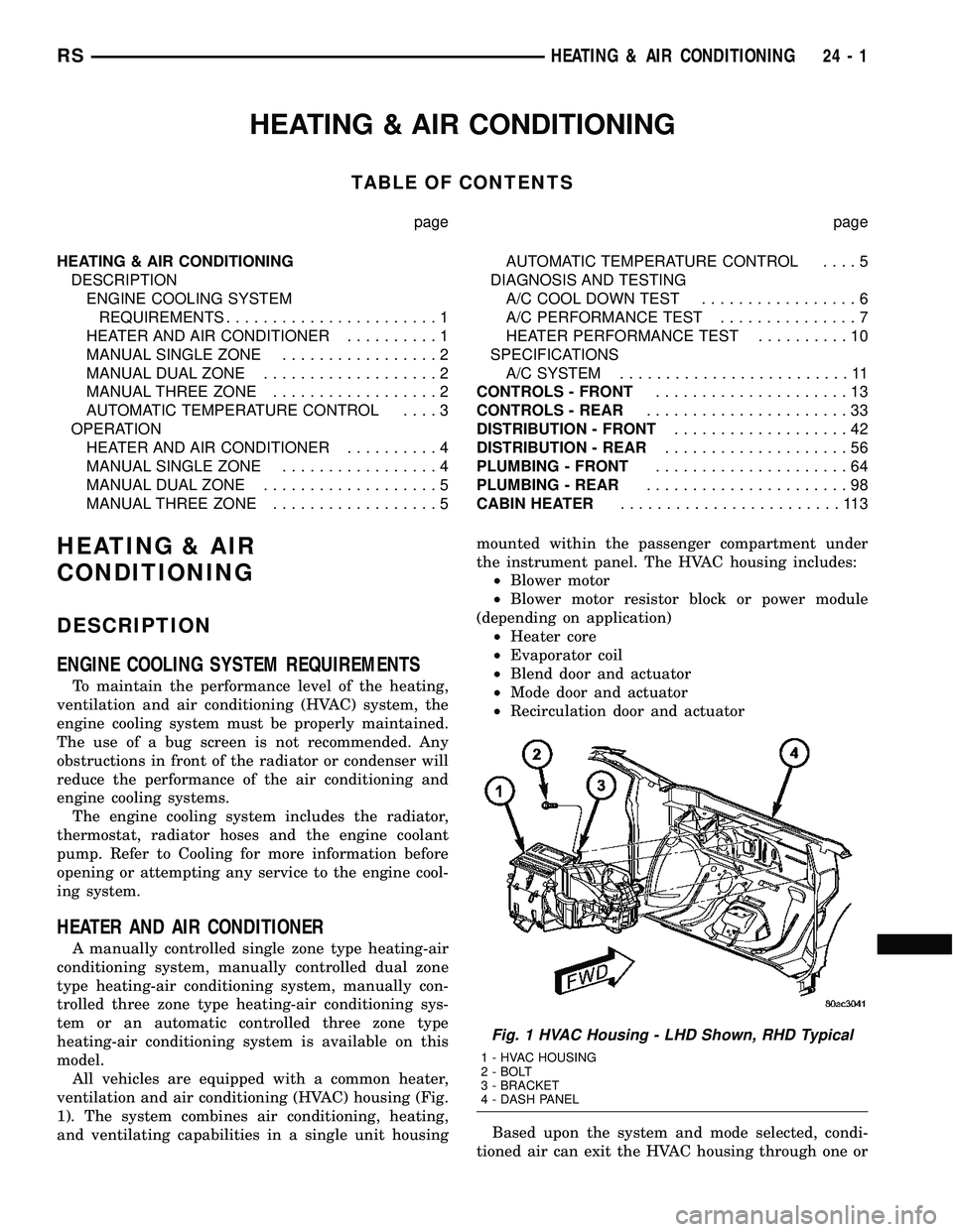
ventilation and air conditioning (HVAC) housing (Fig.
1). The system combines air conditioning, heating,
and ventilating capabilities in a single unit housingmounted within the passenger compartment under
the instrument panel. The HVAC housing includes:
²Blower motor
²Blower motor resistor block or power module
(depending on application)
²Heater core
²Evaporator coil
²Blend door and actuator
²Mode door and actuator
²Recirculation door and actuator
Based upon the system and mode selected, condi-
tioned air can exit the HVAC housing through one or
Fig. 1 HVAC Housing - LHD Shown, RHD Typical
1 - HVAC HOUSING
2 - BOLT
3 - BRACKET
4 - DASH PANEL
RSHEATING & AIR CONDITIONING24-1
Page 2161 of 2339
Condition Possible Causes Correction
The low side pressure is too
low, and the high side
pressure is too high.1. Restricted refrigerant flow
through the refrigerant lines.1. See Liquid Line, Suction Line and Discharge
Line in this group. Inspect the refrigerant lines for
kinks, tight bends or improper routing. Correct
the routing or replace the refrigerant line, if
required.
2. Restricted refrigerant flow
through the A/C expansion
valve.2. See A/C Expansion Valve in this group.
Replace the valve, if required.
3. Restricted refrigerant flow
through the A/C condenser.3. See A/C Condenser in this group. Replace the
restricted condenser, if required.
HEATER PERFORMANCE TEST
WARNING: REVIEW SAFETY PRECAUTIONS AND
WARNINGS IN THIS GROUP BEFORE PERFORMING
THIS PROCEDURE (Refer to 24 - HEATING & AIR
CONDITIONING/PLUMBING - WARNING).
Check the coolant level, drive belt tension, radiator
air flow and fan operation. Start engine and allow to
warm up to normal operating temperature.
WARNING: DO NOT REMOVE RADIATOR CAP
WHEN ENGINE IS HOT, PERSONAL INJURY CAN
RESULT.
If vehicle has been run recently, wait 15 minutes
before removing the radiator cap. Place a rag overthe cap and turn it to the first safety stop. Allow
pressure to escape through the overflow tube. When
the system pressure stabilizes, remove the cap com-
pletely.
MAXIMUM HEATER OUTPUT: TEST AND ACTION
Engine coolant is provided to the heater system by
two heater hoses. With the engine idling at normal
operating temperature, set the temperature control
to maximum heat, the mode control to the floor posi-
tion, and the blower in the highest speed position.
Using a test thermometer, check the temperature of
the air being discharged from the floor outlets. Com-
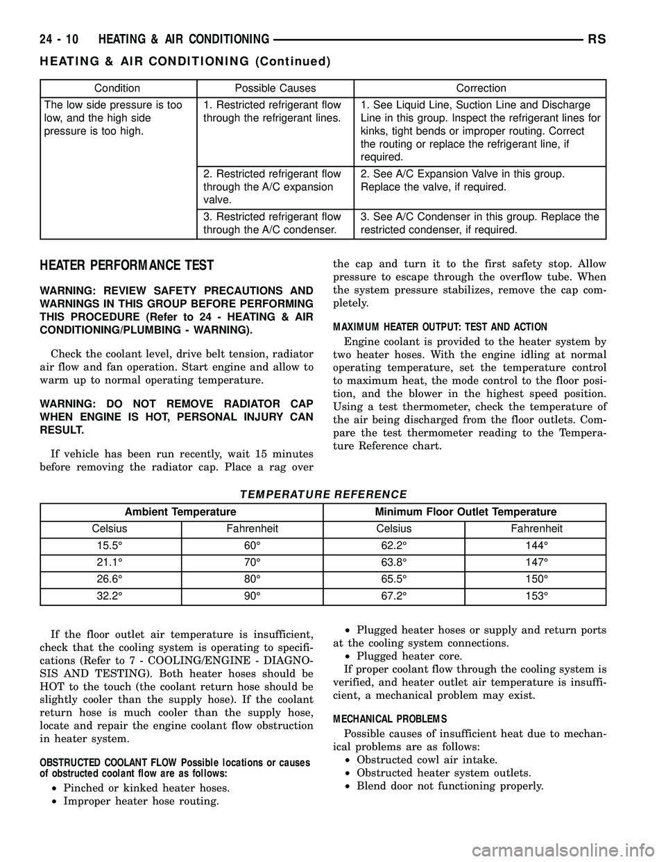
pare the test thermometer reading to the Tempera-
ture Reference chart.
TEMPERATURE REFERENCE
Ambient Temperature Minimum Floor Outlet Temperature
Celsius Fahrenheit Celsius Fahrenheit
15.5É 60É 62.2É 144É
21.1É 70É 63.8É 147É
26.6É 80É 65.5É 150É
32.2É 90É 67.2É 153É
If the floor outlet air temperature is insufficient,
check that the cooling system is operating to specifi-
cations (Refer to 7 - COOLING/ENGINE - DIAGNO-
SIS AND TESTING). Both heater hoses should be
HOT to the touch (the coolant return hose should be
slightly cooler than the supply hose). If the coolant
return hose is much cooler than the supply hose,
locate and repair the engine coolant flow obstruction
in heater system.
OBSTRUCTED COOLANT FLOW Possible locations or causes
of obstructed coolant flow are as follows:
²Pinched or kinked heater hoses.
²Improper heater hose routing.²Plugged heater hoses or supply and return ports
at the cooling system connections.
²Plugged heater core.
If proper coolant flow through the cooling system is
verified, and heater outlet air temperature is insuffi-
cient, a mechanical problem may exist.
MECHANICAL PROBLEMS
Possible causes of insufficient heat due to mechan-
ical problems are as follows:
²Obstructed cowl air intake.
²Obstructed heater system outlets.
²Blend door not functioning properly.
24 - 10 HEATING & AIR CONDITIONINGRS
HEATING & AIR CONDITIONING (Continued)
Page 2171 of 2339
REMOVAL
WARNING: ON VEHICLES EQUIPPED WITH AIR-
BAGS, DISABLE THE AIRBAG SYSTEM BEFORE
ATTEMPTING ANY STEERING WHEEL, STEERING
COLUMN, OR INSTRUMENT PANEL COMPONENT
DIAGNOSIS OR SERVICE. DISCONNECT AND ISO-
LATE THE BATTERY NEGATIVE (GROUND) CABLE,
THEN WAIT TWO MINUTES FOR THE AIRBAG SYS-
TEM CAPACITOR TO DISCHARGE BEFORE PER-
FORMING FURTHER DIAGNOSIS OR SERVICE. THIS
IS THE ONLY SURE WAY TO DISABLE THE AIRBAG
SYSTEM. FAILURE TO TAKE THE PROPER PRE-
CAUTIONS COULD RESULT IN ACCIDENTAL AIR-
BAG DEPLOYMENT AND POSSIBLE PERSONAL
INJURY.
(1) Disconnect and isolate the battery negative
cable.
(2) Remove the center bezel from the instrument
panel (Refer to 23 - BODY/INSTRUMENT PANEL/
INSTRUMENT PANEL CENTER BEZEL -
REMOVAL).
(3) Place the instrument panel center bezel unit
face down on a suitable work surface. Take the
proper precautions to protect the center bezel from
cosmetic damage.
(4) If the vehicle is equipped with the optional
Automatic Temperature Control (ATC) system, dis-
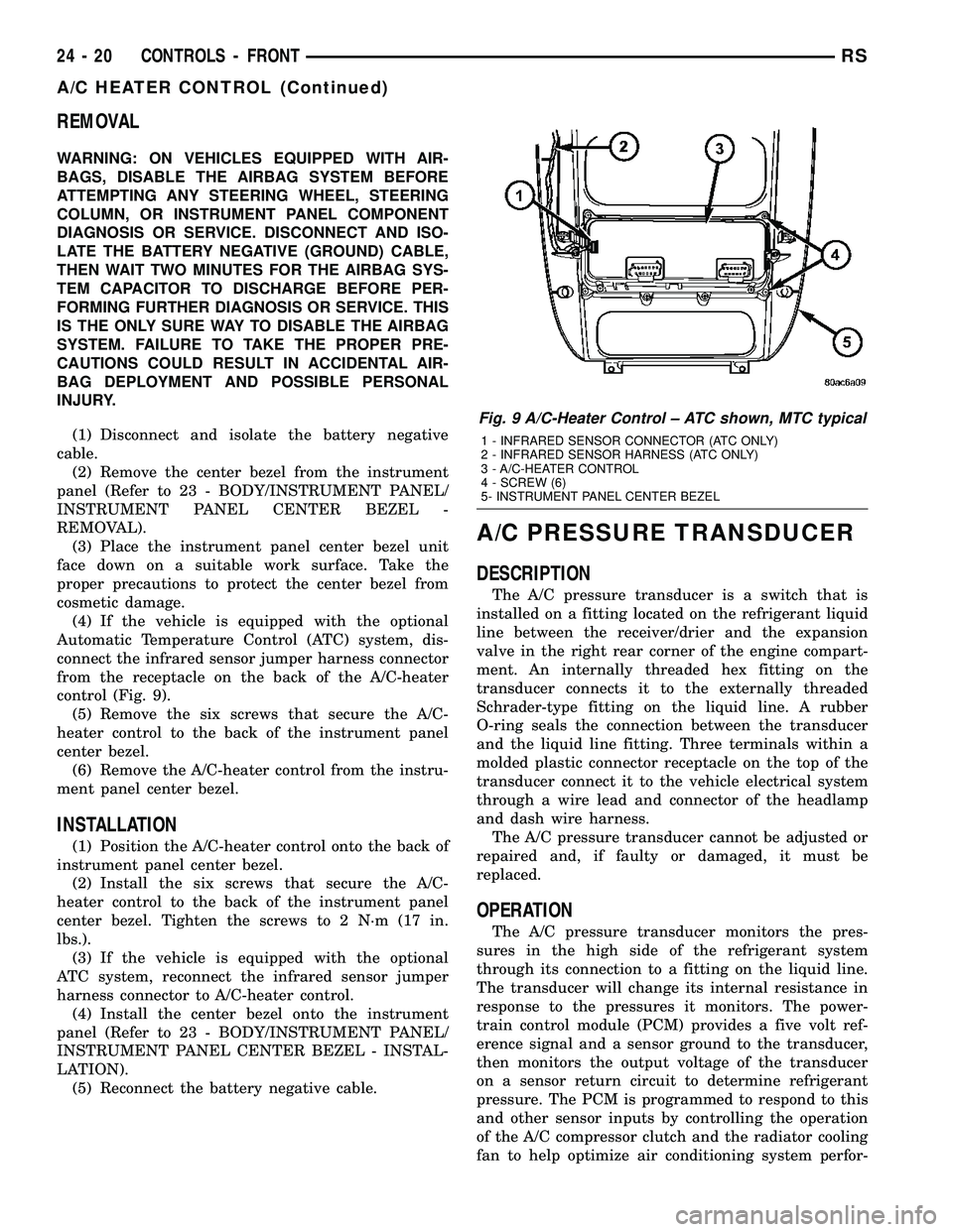
connect the infrared sensor jumper harness connector
from the receptacle on the back of the A/C-heater
control (Fig. 9).
(5) Remove the six screws that secure the A/C-
heater control to the back of the instrument panel
center bezel.
(6) Remove the A/C-heater control from the instru-
ment panel center bezel.
INSTALLATION
(1) Position the A/C-heater control onto the back of
instrument panel center bezel.
(2) Install the six screws that secure the A/C-
heater control to the back of the instrument panel
center bezel. Tighten the screws to 2 N´m (17 in.
lbs.).
(3) If the vehicle is equipped with the optional
ATC system, reconnect the infrared sensor jumper
harness connector to A/C-heater control.
(4) Install the center bezel onto the instrument
panel (Refer to 23 - BODY/INSTRUMENT PANEL/
INSTRUMENT PANEL CENTER BEZEL - INSTAL-
LATION).
(5) Reconnect the battery negative cable.
A/C PRESSURE TRANSDUCER
DESCRIPTION
The A/C pressure transducer is a switch that is
installed on a fitting located on the refrigerant liquid
line between the receiver/drier and the expansion
valve in the right rear corner of the engine compart-
ment. An internally threaded hex fitting on the
transducer connects it to the externally threaded
Schrader-type fitting on the liquid line. A rubber
O-ring seals the connection between the transducer
and the liquid line fitting. Three terminals within a
molded plastic connector receptacle on the top of the
transducer connect it to the vehicle electrical system
through a wire lead and connector of the headlamp
and dash wire harness.
The A/C pressure transducer cannot be adjusted or
repaired and, if faulty or damaged, it must be
replaced.
OPERATION
The A/C pressure transducer monitors the pres-
sures in the high side of the refrigerant system
through its connection to a fitting on the liquid line.
The transducer will change its internal resistance in
response to the pressures it monitors. The power-
train control module (PCM) provides a five volt ref-
erence signal and a sensor ground to the transducer,
then monitors the output voltage of the transducer
on a sensor return circuit to determine refrigerant
pressure. The PCM is programmed to respond to this
and other sensor inputs by controlling the operation
of the A/C compressor clutch and the radiator cooling
fan to help optimize air conditioning system perfor-
Fig. 9 A/C-Heater Control ± ATC shown, MTC typical
1 - INFRARED SENSOR CONNECTOR (ATC ONLY)
2 - INFRARED SENSOR HARNESS (ATC ONLY)
3 - A/C-HEATER CONTROL
4 - SCREW (6)
5- INSTRUMENT PANEL CENTER BEZEL
24 - 20 CONTROLS - FRONTRS
A/C HEATER CONTROL (Continued)
Page 2216 of 2339
PLUMBING - FRONT
DESCRIPTION
CAUTION: The system must be completely empty
before opening any fitting or connection in the
refrigeration system. Open fittings with caution
even after the system has been emptied. If any
pressure is noticed as a fitting is loosened,
retighten fitting and evacuate the system again.
The use of correct wrenches when making connec-
tions is very important. Improper wrenches or
improper use of wrenches can damage the fittings.
The internal parts of the A/C system will remain sta-
ble as long as moisture-free refrigerant and refrig-
erant oil is used. Abnormal amounts of dirt,
moisture or air can upset the chemical stability.
This may cause operational troubles or even seri-
ous damage if present in more than very small
quantities. Before disconnecting a refrigerant line
or hose, clean the outside of the fittings thoroughly
to prevent contamination from entering the refriger-
ant system.
When opening a refrigeration system, have every-
thing you will need to repair the system ready to
minimize the amount of time the system is opened.
Cap or plug all refrigerant line fittings as soon as
they are opened. This will help prevent the entrance
of dirt and moisture. All new lines and components
should be capped or sealed until they are ready to
be used. Before connecting a refrigerant line or
hose, clean the outside of the fittings thoroughly to
prevent contamination from entering the refrigerant
system.
All tools, including the refrigerant dispensing mani-
fold, manifold gauge set and test hoses should be
kept clean and dry.
The A/C refrigerant lines and hoses are used to
carry the refrigerant between the various A/C system
components. The refrigerant lines and hoses for the
R-134a system on this vehicle consist of a barrier-
hose design with a nylon tube sandwiched between
rubber layers. The nylon tube helps to contain the
R-134a refrigerant, which has a smaller molecular
structure than R-12 refrigerant. The ends of the
refrigerant lines are made from lightweight alumi-
num or steel, and commonly use braze-less fittings.Any kinks or sharp bends in the refrigerant lines
and hoses will reduce the capacity of the entire A/C
system and can reduce the flow of refrigerant in the
system. The radius of all bends in the flexible hose
refrigerant lines should be at least ten times the
diameter of the hose and the refrigerant lines should
be routed so they are at least 80 millimeters (3
inches) away from the exhaust manifold(s) and
exhaust pipe(s).
OPERATION
High pressures are produced in the refrigerant sys-
tem when the A/C compressor is operating. Extreme
care must be exercised to make sure that each of the
refrigerant system connections is pressure-tight and
leak free. It is a good practice to inspect all flexible
hose refrigerant lines at least once a year to make
sure they are in good condition and properly routed.
The refrigerant lines and hoses are coupled to
other A/C system components with block-type fit-
tings. An O-ring seal, or a flat steel gasket with an
integral O-ring (dual plane seal), is used to mate the
refrigerant line fittings with A/C system components
to ensure the integrity of the refrigerant system.
The refrigerant lines and hoses cannot be repaired
and, if faulty or damaged, they must be replaced.
WARNING
ENGINE COOLING SYSTEM
WARNING: THE ENGINE COOLING SYSTEM IS
DESIGNED TO DEVELOP INTERNAL PRESSURES
OF 97 TO 123 KILOPASCALS (14 TO 18 POUNDS
PER SQUARE INCH). DO NOT REMOVE OR
LOOSEN THE COOLANT PRESSURE CAP, CYLIN-
DER BLOCK DRAIN PLUGS, RADIATOR DRAIN,
RADIATOR HOSES, HEATER HOSES, OR HOSE
CLAMPS WHILE THE ENGINE COOLING SYSTEM IS
HOT AND UNDER PRESSURE. FAILURE TO
OBSERVE THIS WARNING CAN RESULT IN SERI-
OUS BURNS FROM THE HEATED ENGINE COOL-
ANT. ALLOW THE VEHICLE TO COOL FOR A
MINIMUM OF 15 MINUTES BEFORE OPENING THE
COOLING SYSTEM FOR SERVICE.
RSPLUMBING - FRONT24-65
Page 2253 of 2339

(5) Install the rear evaporator line extension onto
the expansion valve (Refer to 24 - HEATING & AIR
CONDITIONING/PLUMBING - REAR/EVAPORA-
TOR - INSTALLATION - EVAPORATOR LINE
EXTENSION).
(6) Install the foam insulator wrap over the rear
expansion valve.
(7) Install the rear HVAC housing (Refer to 24 -
HEATING & AIR CONDITIONING/DISTRIBUTION/
HVAC HOUSING - INSTALLATION).
(8) Run the HVAC Cooldown Test to verify proper
operation.
HEATER CORE
DESCRIPTION
The rear heater core is located near the front of
the rear HVAC housing, behind the right rear wheel
house. It is a heat exchanger made of rows of tubes
and fins. One end of the core is fitted with a molded
plastic tank that includes integral heater core inlet
and outlet nipples. The rear heater core can be ser-
viced without removing the rear HVAC housing from
the vehicle.
OPERATION
Engine coolant is circulated through underbody
heater hoses to the rear heater core at all times. As
the coolant flows through the rear heater core, heat
removed from the engine is transferred to the heater
core fins and tubes. Air directed through the heater
core picks up the heat from the heater core fins. The
rear blend door allows control of the rear heater out-
put air temperature by controlling how much of the
air flowing through the rear HVAC housing is
directed through the heater core.
The rear heater core cannot be repaired and, if
faulty or damaged, it must be replaced.
STANDARD PROCEDURE
REAR HEATER CORE FILLING
In its final installed position, the rear heater core
is positioned higher than the radiator fill cap. There-
fore, when the cooling system is drained and refilled,
gravity will not refill the heater core with coolant to
the proper level. This may result in two problems:1.
Insufficient coolant level in the engine cooling sys-
tem, which may result in engine overheating.2.Air
entrapped within the rear heater core, which may
result in insufficient rear heater performance. There
are two methods that may be employed to prevent
these problems:1.Pre-filling of the rear heater core.
2.Thermal cycling of the engine cooling system. Fol-lowing are descriptions of both prevention methods,
as well as a method to verify rear heater perfor-
mance.
WARNING: REFER TO THE APPLICABLE WARN-
INGS AND CAUTIONS FOR THIS SYSTEM BEFORE
PERFORMING THE FOLLOWING OPERATION (Refer
to 24 - HEATING & AIR CONDITIONING/PLUMBING
FRONT - WARNING - HEATER PLUMBING).
PRE-FILLING
If the rear heater core or the rear HVAC housing
have been removed from the vehicle for service, the
rear heater core may be pre-filled with the proper
engine coolant mixture prior to reconnecting the
heater hoses to the heater core hose fittings.
(1) The heater core should be installed in the rear
HVAC housing, and the rear HVAC housing should
be installed in the vehicle.
(2) Take the proper precautions to protect the car-
peting below the rear heater core from spilled engine
coolant and have absorbent toweling readily avail-
able to mop up any spills.
(3) Insert the small end of an appropriate funnel
into the upper hose fitting of the heater core (Fig. 4).
(4) Carefully pour the proper pre-mixed engine
coolant solution into the rear heater core through a
funnel until coolant begins to appear at the lower
hose fitting of the heater core.
(5) Use absorbent toweling to clean up any engine
coolant spills from the preceding operation.
(6) Reconnect the heater hoses to the rear heater
core (Refer to 24 - HEATING & AIR CONDITION-
ING/PLUMBING - REAR/HEATER HOSE - INSTAL-
LATION).
Fig. 4 Pre-Filling Heater Core - Typical
1 - REAR HEATER CORE
24 - 102 PLUMBING - REARRS
A/C EXPANSION VALVE (Continued)
Page 2307 of 2339
CABLE END CLEANING ANDLUBRICATION - STANDARD
PROCEDURE ......................... 5-65
CABLE RESISTANCE, SPECIFICATIONS - SPARK PLUG ......................... 8I-2
CABLES - ADJUSTMENT, PARKING BRAKE .............................. 5-65
CABLES - DESCRIPTION, BATTERY .......8F-16
CABLES - OPERATION, BATTERY ........8F-17
CABLES, DIAGNOSIS AND TESTING - BATTERY ........................... 8F-17
CALIBRATION, STANDARD PROCEDURE - A/C-HEATER CONTROL ................24-19
CALIBRATION, STANDARD PROCEDURE - COMPASS ........................... 8M-4
CALIPER - CLEANING ..............5-25,5-29
CALIPER - INSPECTION ............5-25,5-29
CALIPER - INSTALLATION, REAR DISC BRAKE .............................. 5-30
CALIPER - REMOVAL, REAR DISC BRAKE .............................. 5-28
CALIPER ADAPTER - INSTALLATION, FRONT DISC BRAKE ................... 5-31
CALIPER ADAPTER - REMOVAL, FRONT DISC BRAKE ......................... 5-31
CALIPER (CONTINENTAL TEVES BRAKES) - INSTALLATION, FRONT
DISC BRAKE ......................... 5-27
CALIPER (CONTINENTAL TEVES BRAKES) - REMOVAL, FRONT DISC
BRAKE .............................. 5-24
CALIPER GUIDE PIN BUSHINGS (CONTINENTAL TEVES BRAKES) -
ASSEMBLY ............................ 5-25
CALIPER GUIDE PIN BUSHINGS (CONTINENTAL TEVES BRAKES) -
DISASSEMBLY ........................ 5-24
CALIPER GUIDE PINS (TRW BRAKES) - INSTALLATION, DISC BRAKE ............5-32
CALIPER GUIDE PINS (TRW BRAKES) - REMOVAL, DISC BRAKE ................5-31
CALIPER PISTON AND SEAL - ASSEMBLY ...................... 5-26,5-30
CALIPER PISTON AND SEAL - DISASSEMBLY .................... 5-24,5-28
CALIPER (TRW BRAKES) - INSTALLATION, FRONT DISC BRAKE ......5-27
CALIPER (TRW BRAKES) - REMOVAL, FRONT DISC BRAKE ................... 5-24
CAMSHAFT & BEARINGS (IN BLOCK) - DESCRIPTION ....................... 9-118
CAMSHAFT & BEARINGS (IN BLOCK) - INSPECTION ........................ 9-118
CAMSHAFT & BEARINGS (IN BLOCK) - INSTALLATION ....................... 9-118
CAMSHAFT & BEARINGS (IN BLOCK) - OPERATION ......................... 9-118
CAMSHAFT & BEARINGS (IN BLOCK) - REMOVAL .......................... 9-118
CAMSHAFT END PLAY - STANDARD PROCEDURE, MEASURING ..............9-29
CAMSHAFT OIL SEAL(S) - INSTALLATION . . 9-29
CAMSHAFT OIL SEAL(S) - REMOVAL ......9-28
CAMSHAFT POSITION SENSOR - DESCRIPTION ......................... 8I-4
CAMSHAFT POSITION SENSOR - OPERATION .......................... 8I-4
CAMSHAFT SPROCKET - INSTALLATION, TIMING CHAIN ....................... 9-160
CAMSHAFT SPROCKET - REMOVAL, TIMING CHAIN ....................... 9-159
CAMSHAFT SPROCKETS - INSTALLATION . . 9-67
CAMSHAFT SPROCKETS - REMOVAL ......9-66
CAMSHAFT(S) - CLEANING ..............9-30
CAMSHAFT(S) - DESCRIPTION ...........9-29
CAMSHAFT(S) - INSPECTION ............9-30
CAMSHAFT(S) - INSTALLATION ..........9-31
CAMSHAFT(S) - OPERATION .............9-29
CAMSHAFT(S) - REMOVAL ..............9-30
CANISTER - DESCRIPTION, VAPOR ......25-19
CANISTER - INSTALLATION, REAR EVAP . . 25-21
CANISTER - OPERATION, VAPOR ........25-19
CANISTER - REMOVAL, REAR EVAP ......25-20
CAP - DESCRIPTION, FUEL FILLER .......25-13
CAP - DESCRIPTION, RADIATOR PRESSURE .......................... 7-27
CAP - INSTALLATION, INSTRUMENT PANEL RIGHT END ................... 23-72CAP - OPERATION, FUEL FILLER
........25-13
CAP - OPERATION, RADIATOR PRESSURE .......................... 7-27
CAP - REMOVAL, INSTRUMENT PANEL RIGHT END ......................... 23-72
CAP TESTING - DIAGNOSIS AND TESTING, COOLING SYSTEM
PRESSURE .......................... 7-28
CAP TO FILLER NECK SEAL - DIAGNOSIS AND TESTING, RADIATOR .....7-28
CAPACITIES - SPECIFICATIONS, FLUID ......0-6
CARE, CLEANING - WHEEL AND WHEEL TRIM .............................. 22-19
CARGO - INSTALLATION, AWD, HEAVY DUTY ............................... 2-36
CARGO - INSTALLATION, SPRING ........2-40
CARGO - REMOVAL, AWD, HEAVY DUTY . . . 2-36
CARGO - REMOVAL, SPRING ............2-40
CARPET INSERT - FOLD-IN-FLOOR - INSTALLATION, SECOND ROW FLOOR
TUB ............................... 23-98
CARPET INSERT - FOLD-IN-FLOOR - REMOVAL, SECOND ROW FLOOR TUB ....23-98
CARPET TRIM RING AND COVER - FOLD-IN-FLOOR - INSTALLATION ........23-84
CARPET TRIM RING AND COVER - FOLD-IN-FLOOR - REMOVAL ............23-84
CARPETS - FOLD-IN-FLOOR - INSTALLATION ....................... 23-83
CARPETS - FOLD-IN-FLOOR - REMOVAL . . 23-82
CARPETS AND FLOOR MATS - INSTALLATION ....................... 23-81
CARPETS AND FLOOR MATS - REMOVAL . 23-81
CARPETS INSERT - FOLD-IN-FLOOR - INSTALLATION, REAR FLOOR TUB .......23-96
CARPETS INSERT - FOLD-IN-FLOOR - REMOVAL, REAR FLOOR TUB ...........23-95
CARRIER ASSEMBLY - DESCRIPTION, BALANCE SHAFTS ..................... 9-71
CARRIER ASSEMBLY - INSTALLATION, BALANCE SHAFTS ..................... 9-73
CARRIER ASSEMBLY - OPERATION, BALANCE SHAFTS ..................... 9-71
CARRIER ASSEMBLY - REMOVAL, BALANCE SHAFTS ..................... 9-71
CATALYTIC CONVERTER - DESCRIPTION . . . 11-4
CATALYTIC CONVERTER - INSPECTION ....11-6
CATALYTIC CONVERTER - INSTALLATION . . . 11-6
CATALYTIC CONVERTER - OPERATION .....11-4
CATALYTIC CONVERTER - REMOVAL ......11-5
CAUTION, A/C SYSTEM ................24-66
CAUTION, DESCRIPTION .................5-4
CAUTION, DESCRIPTION ...............19-37
CAUTION, OPERATION .................5-90
CAUTION, SENSOR - TPM ..............22-11
CAUTIONS, WARNING - WARNINGS . 19-10,19-26
CD CHANGER - DESCRIPTION ..........8A-11
CD CHANGER - INSTALLATION ..........8A-11
CD CHANGER - OPERATION ............8A-11
CD CHANGER - REMOVAL .............8A-11
CENTER - DESCRIPTION, ELECTRONIC VEHICLE INFO ....................... 8M-7
CENTER - INSTALLATION, MESSAGE ......8M-1
CENTER - OPERATION, ELECTRONIC VEHICLE INFO ....................... 8M-7
CENTER - REMOVAL, MESSAGE .........8M-1
CENTER BEZEL - INSTALLATION, INSTRUMENT PANEL .................. 23-72
CENTER BEZEL - REMOVAL, INSTRUMENT PANEL .................. 23-71
CENTER BEZEL OUTLETS, INSTALLATION - FRONT ............................ 24-45
CENTER BEZEL OUTLETS, REMOVAL - FRONT ............................. 24-44
CENTER CONSOLE LAMP - INSTALLATION ....................... 8L-21
CENTER CONSOLE LAMP - REMOVAL ....8L-21
CENTER CONSOLE LAMP SWITCH - INSTALLATION ....................... 8L-21
CENTER CONSOLE LAMP SWITCH - REMOVAL .......................... 8L-21
CENTER, DIAGNOSIS AND TESTING - ELECTRONIC VEHICLE INFORMATION .....8M-8
CENTER HIGH MOUNTED STOP LAMP - INSTALLATION ........................ 8L-6
CENTER HIGH MOUNTED STOP LAMP - REMOVAL ........................... 8L-6CENTER HIGH MOUNTED STOP LAMP
UNIT - INSTALLATION .................. 8L-6
CENTER HIGH MOUNTED STOP LAMP UNIT - REMOVAL ..................... 8L-6
CENTER HINGE - INSTALLATION .........23-24
CENTER HINGE - REMOVAL ............23-24
CENTER LAP BELT - FOLD-IN-FLOOR - INSTALLATION, SEAT BELT ............23-157
CENTER LAP BELT - FOLD-IN-FLOOR - REMOVAL, SEAT BELT ................23-157
CENTER PROGRAMMING, STANDARD PROCEDURE - ELECTRONIC VEHICLE
INFORMATION ....................... 8M-8
CENTER STRIKER - INSTALLATION .......23-28
CENTER STRIKER - REMOVAL ..........23-28
CENTERING - STANDARD PROCEDURE, CLOCKSPRING ...................... 8O-11
CHAIN AND CAMSHAFT SPROCKET - INSTALLATION, TIMING ................9-160
CHAIN AND CAMSHAFT SPROCKET - REMOVAL, TIMING ................... 9-159
CHAIN COVER - INSTALLATION, TIMING . . 9-157
CHAIN COVER - REMOVAL, TIMING ......9-156
CHAIN WEAR - STANDARD PROCEDURE, MEASURING TIMING .................. 9-155
CHANGE - STANDARD PROCEDURE, ENGINE OIL AND FILTER ...........9-139,9-54
CHANGER - DESCRIPTION, CD ..........8A-11
CHANGER - INSTALLATION, CD .........8A-11
CHANGER - OPERATION, CD ............8A-11
CHANGER - REMOVAL, CD ..............8A-11
CHANNEL - INSTALLATION, WATER .....23-174
CHANNEL - REMOVAL, WATER .........23-174
CHARGE LEVEL TEST, DIAGNOSIS AND TESTING - SYSTEM ................... 24-67
CHARGE, STANDARD PROCEDURE - REFRIGERANT SYSTEM ...............24-71
CHARGING, STANDARD PROCEDURE - CONVENTIONAL BATTERY ..............8F-11
CHARGING, STANDARD PROCEDURE - SPIRAL PLATE BATTERY ...............8F-10
CHARGING SYSTEM - DESCRIPTION .....8F-21
CHARGING SYSTEM - OPERATION .......8F-21
CHARTS - DIAGNOSIS AND TESTING, STEERING SYSTEM DIAGNOSIS ..........19-3
CHARTS - SPECIFICATIONS, COLOR CODE ............................. 23-100
CHECK - DIAGNOSIS AND TESTING, COOLING SYSTEM FLOW ................7-3
CHECK - DIAGNOSIS AND TESTING, EXHAUST SYSTEM RESTRICTION .........11-2
CHECK - STANDARD PROCEDURE, COOLANT LEVEL .......................7-4
CHECK - STANDARD PROCEDURE, ENGINE OIL LEVEL ................... 9-140
CHECK, STANDARD PROCEDURE - ENGINE OIL LEVEL .................... 9-54
CHECK, STANDARD PROCEDURE - FLUID LEVEL AND CONDITION .........21-230,21-82
CHECK STRAP - INSTALLATION .........23-15
CHECK STRAP - REMOVAL .............23-15
CHECKING - STANDARD PROCEDURE, BRAKE FLUID LEVEL ................... 5-33
CHECKING - STANDARD PROCEDURE, POWER STEERING FLUID LEVEL ........19-44
CHECKING BATTERY ELECTROLYTE LEVEL, STANDARD PROCEDURE .........8F-14
CHECKING ENGINE OIL PRESSURE - DIAGNOSIS AND TESTING ..............9-53
CHECKING POWER STEERING BELT TENSION - STANDARD PROCEDURE .......7-8
CHILD RESTRAINT ANCHOR - DESCRIPTION ........................ 8O-9
CHILD RESTRAINT ANCHOR - OPERATION ......................... 8O-10
CHILD SEAT - INSTALLATION, QUAD ....23-106
CHILD SEAT - REMOVAL, QUAD ........23-106
CHILD SEAT MODULE, BENCH SEAT - REMOVAL ......................... 23-104
CHIME SYSTEM - DIAGNOSIS AND TESTING ............................ 8B-2
CHIME/BUZZER - DESCRIPTION ..........8B-1
CHIME/BUZZER - OPERATION ............8B-1
CHIME/BUZZER - WARNING .............8B-2
CHIME/THERMISTOR - DESCRIPTION .....8N-8
CHIME/THERMISTOR - INSTALLATION .....8N-9
CHIME/THERMISTOR - OPERATION .......8N-8
CHIME/THERMISTOR - REMOVAL ........8N-8
6 INDEXRS
Description Group-Page Description Group-Page Description Group-Page
Page 2312 of 2339

DOOR WEATHERSTRIP - INSTALLATION,SLIDING ........................... 23-168
DOOR WEATHERSTRIP - REMOVAL, FRONT ............................ 23-168
DOOR WEATHERSTRIP - REMOVAL, SLIDING ........................... 23-168
DOSING PUMP - DESCRIPTION, FUEL . . . 24-117
DOSING PUMP - INSTALLATION, FUEL . . . 24-117
DOSING PUMP - OPERATION, FUEL .....24-117
DOSING PUMP - REMOVAL, FUEL ......24-117
DOWNSTREAM 1/2 - 2.4/3.3/3.8L - REMOVAL .......................... 14-38
DOWNSTREAM 2/1, 2.4/3.3/3.8L - INSTALLATION ....................... 14-39
D-PILLAR TRIM PANEL - INSTALLATION, LEFT .............................. 23-94
D-PILLAR TRIM PANEL - INSTALLATION, RIGHT ............................. 23-98
D-PILLAR TRIM PANEL - REMOVAL, LEFT .............................. 23-94
D-PILLAR TRIM PANEL - REMOVAL, RIGHT ............................. 23-97
DRAIN TUBE - INSTALLATION ..........23-172
DRAIN TUBE - REMOVAL .............23-172
DRAINCOCK - INSTALLATION, RADIATOR . . . 7-27
DRAINCOCK - REMOVAL, RADIATOR ......7-27
DRAINING - STANDARD PROCEDURE, COOLING SYSTEM .....................7-4
DRAINING FUEL TANK - STANDARD PROCEDURE ......................... 14-2
DRAW TEST, STANDARD PROCEDURE - IGNITION-OFF ....................... 8F-13
DRB III TSTATE DISPLAY TEST MODE,
OPERATION ......................... 25-10
DRIER - DESCRIPTION, RECEIVER .......24-92
DRIER - INSTALLATION, RECEIVER ......24-93
DRIER - OPERATION, RECEIVER .........24-92
DRIER - REMOVAL, RECEIVER ..........24-92
DRIVE - ASSEMBLY, FINAL .......21-224,21-78
DRIVE - DESCRIPTION, FINAL ....21-219,21-74
DRIVE - DESCRIPTION, FLEX ...........8N-55
DRIVE - DISASSEMBLY, FINAL ....21-220,21-75
DRIVE - INSTALLATION, FLEX ..........8N-56
DRIVE - OPERATION, FINAL ......21-220,21-75
DRIVE - OPERATION, FLEX .............8N-55
DRIVE - REMOVAL, FLEX ..............8N-55
DRIVE BELT - DIAGNOSIS AND TESTING, ACCESSORY ..........................7-7
DRIVE BELT TENSION, SPECIFICATIONS - ACCESSORY ..........................7-5
DRIVE BELTS - 2.4L - ADJUSTMENTS .....7-10
DRIVE BELTS - 2.4L - INSTALLATION .......7-9
DRIVE BELTS - 2.4L - REMOVAL ..........7-9
DRIVE BELTS - 3.3/3.8L - INSTALLATION . . . 7-12
DRIVE BELTS - 3.3/3.8L - REMOVAL ......7-11
DRIVE BELTS - CLEANING ...............7-8
DRIVE BELTS - INSPECTION ..............7-8
DRIVE UNIT - DESCRIPTION, LOWER ....8N-53
DRIVE UNIT - INSTALLATION, LOWER ....8N-54
DRIVE UNIT - OPERATION, LOWER ......8N-53
DRIVE UNIT - REMOVAL, LOWER .......8N-53
DRIVE UNIT TRACK & RACK - DESCRIPTION, LOWER ................8N-57
DRIVE UNIT TRACK & RACK - INSTALLATION, LOWER ...............8N-58
DRIVE UNIT TRACK & RACK - OPERATION, LOWER .................. 8N-57
DRIVE UNIT TRACK & RACK - REMOVAL, LOWER ................... 8N-57
DRIVELINE MODULE FLUIDS - DESCRIPTION, AWD REAR ...............0-6
DRIVER AIRBAG - DESCRIPTION ........8O-16
DRIVER AIRBAG - INSTALLATION .......8O-18
DRIVER AIRBAG - OPERATION ..........8O-16
DRIVER AIRBAG - REMOVAL ...........8O-17
DRIVER HEATED SEAT SWITCH, DIAGNOSIS AND TESTING ..............8G-9
DRIVER SEAT SWITCH, DIAGNOSIS AND TESTING ........................... 8N-34
DRIVING CLUTCHES - DESCRIPTION ....21-219,
21-74
DRIVING CLUTCHES - OPERATION . 21-219,21-74
DROP - STANDARD PROCEDURE, TESTING FOR A VOLTAGE ...........8W-01-10
DRUM - INSTALLATION .................5-32
DRUM - REMOVAL .................... 5-32
DRUM BRAKE - INSTALLATION, SUPPORT PLATE ...................... 5-61DRUM BRAKE - REMOVAL, SUPPORT
PLATE .............................. 5-61
DRUM BRAKE AUTOMATIC ADJUSTER - DIAGNOSIS AND TESTING ..............5-14
DRUM BRAKE SHOE LINING - INSPECTION, REAR .................... 5-22
DRUM BRAKE SHOES - ADJUSTMENT, REAR ............................... 5-23
DRUM BRAKE SHOES - INSTALLATION, REAR ............................... 5-22
DRUM BRAKE SHOES - REMOVAL, REAR . . 5-19
DRUM BRAKES (REAR) - DESCRIPTION ....5-13
DUAL ZONE, DESCRIPTION - MANUAL .....24-2
DUAL ZONE, OPERATION - MANUAL ......24-5
DUCT - INSTALLATION, DEFROSTER .....24-50
DUCT - INSTALLATION, DISTRIBUTION . . . 24-57
DUCT - INSTALLATION, REAR FLOOR HEAT .............................. 24-63
DUCT - REMOVAL, DEFROSTER .........24-49
DUCT - REMOVAL, DISTRIBUTION .......24-57
DUCT - REMOVAL, REAR FLOOR HEAT . . . 24-63
DUCTS - INSTALLATION, FLOOR DISTRIBUTION ....................... 24-50
DUCTS - INSTALLATION, INSTRUMENT PANEL ............................. 24-55
DUCTS - INSTALLATION, INSTRUMENT PANEL DEMISTER .................... 24-54
DUCTS - REMOVAL, FLOOR DISTRIBUTION ....................... 24-50
DUCTS - REMOVAL, INSTRUMENT PANEL .............................. 24-55
DUCTS - REMOVAL, INSTRUMENT PANEL DEMISTER .................... 24-54
DUTY, CARGO - INSTALLATION, AWD, HEAVY.............................. 2-36
DUTY, CARGO - REMOVAL, AWD, HEAVY . . . 2-36
DVD PLAYER - DESCRIPTION ...........8A-12
DVD PLAYER - INSTALLATION ..........8A-12
DVD PLAYER - REMOVAL ..............8A-12
ELECTRIC BACKLIGHT (EBL) SYSTEM, DIAGNOSIS AND TESTING ..............8G-2
ELECTROLYTE LEVEL, STANDARD PROCEDURE - CHECKING BATTERY ......8F-14
ELECTRONIC VARIABLE BRAKE PROPORTIONING - DESCRIPTION ........5-88
ELECTRONIC VARIABLE BRAKE PROPORTIONING - OPERATION ..........5-89
ELECTRONIC VEHICLE INFO CENTER - DESCRIPTION ........................ 8M-7
ELECTRONIC VEHICLE INFO CENTER - OPERATION ......................... 8M-7
ELECTRONIC VEHICLE INFORMATION CENTER, DIAGNOSIS AND TESTING ......8M-8
ELECTRONIC VEHICLE INFORMATION CENTER PROGRAMMING, STANDARD
PROCEDURE ......................... 8M-8
ELECTROSTATIC DISCHARGE (ESD) SENSITIVE DEVICES - STANDARD
PROCEDURE ......................8W -01-8
ELEMENT - INSTALLATION, AIR CLEANER ....................... 9-101,9-24
ELEMENT - REMOVAL, AIR CLEANER . 9-101,9-24
ELEMENTS - DESCRIPTION, HEATED SEAT .............................. 8G-11
ELEMENTS - OPERATION, HEATED SEAT . . 8G-11
ELEMENTS, DIAGNOSIS AND TESTING - HEATED SEAT ....................... 8G-11
EMISSION CONTROL INFORMATION LABEL, DESCRIPTION - VEHICLE .........25-1
END CAP - INSTALLATION, INSTRUMENT PANEL RIGHT ....................... 23-72
END CAP - REMOVAL, INSTRUMENT PANEL RIGHT ....................... 23-72
END CLEANING AND LUBRICATION - STANDARD PROCEDURE, CABLE .........5-65
END PLAY - STANDARD PROCEDURE, CRANKSHAFT ........................ 9-37
END PLAY - STANDARD PROCEDURE, MEASURING CAMSHAFT ................9-29
END PLAY - STANDARD PROCEDURE, MEASURING CRANKSHAFT .............9-128
ENGAGE ACTUATOR - DESCRIPTION ......8N-9
ENGAGE ACTUATOR - INSTALLATION .....8N-10
ENGAGE ACTUATOR - OPERATION ........8N-9
ENGAGE ACTUATOR - REMOVAL .........8N-9
ENGINE - A/C COMPRESSOR MOUNTING BRACKET, 2.4L ................. 24-74,24-75
ENGINE - CLEANING ................... 7-18ENGINE - DESCRIPTION, 2.4L/3.3L/3.8L . . . 19-52
ENGINE - DESCRIPTION, FUEL
REQUIREMENTS - DIESEL ...............0-6
ENGINE - INSPECTION .................7-18
ENGINE - INSTALLATION, 2.4L .....19-47,19-50,
19-51,19-53
ENGINE - INSTALLATION, 3.3L/3.8L . 19-48,19-50, 19-52,19-53
ENGINE - REMOVAL, 2.4L . . . 19-46,19-49,19-51, 19-52
ENGINE - REMOVAL, 3.3L/3.8L ....19-46,19-49,
19-51,19-52
ENGINE - SPECIFICATIONS, 2.4L .........9-16
ENGINE 2.4L - DESCRIPTION .............9-3
ENGINE 3.3/3.8L - DESCRIPTION .........9-78
ENGINE ASSEMBLY - INSTALLATION . . 9-14,9-91
ENGINE ASSEMBLY - REMOVAL ......9-12,9-88
ENGINE BLOCK - CLEANING ........9-115,9-37
ENGINE BLOCK - DESCRIPTION .....9-115,9-36
ENGINE BLOCK - INSPECTION ......9-115,9-37
ENGINE BLOCK HEATER - DESCRIPTION . . . 7-20
ENGINE BLOCK HEATER - INSTALLATION . . . 7-21
ENGINE BLOCK HEATER - OPERATION .....7-20
ENGINE BLOCK HEATER - REMOVAL ......7-21
ENGINE BLOCK HEATER TESTING - DIAGNOSIS AND TESTING ..............7-21
ENGINE COOLANT - DESCRIPTION ........7-19
ENGINE COOLANT - DESCRIPTION .........0-3
ENGINE COOLANT TEMPERATURE SENSOR - 2.4L - DESCRIPTION ..........7-21
ENGINE COOLANT TEMPERATURE SENSOR - 2.4L - INSTALLATION ..........7-21
ENGINE COOLANT TEMPERATURE SENSOR - 2.4L - REMOVAL .............7-21
ENGINE COOLANT TEMPERATURE SENSOR - 3.3/3.8L - DESCRIPTION .......7-21
ENGINE COOLANT TEMPERATURE SENSOR - 3.3/3.8L - INSTALLATION .......7-23
ENGINE COOLANT TEMPERATURE SENSOR - 3.3/3.8L - REMOVAL ..........7-21
ENGINE COOLANT THERMOSTAT - 2.4L - INSTALLATION ........................ 7-24
ENGINE COOLANT THERMOSTAT - 2.4L - REMOVAL ........................... 7-24
ENGINE COOLANT THERMOSTAT - 3.3/3.8L - INSTALLATION ...............7-25
ENGINE COOLANT THERMOSTAT - 3.3/3.8L - REMOVAL ................... 7-24
ENGINE COOLANT THERMOSTAT - DESCRIPTION ........................ 7-23
ENGINE COOLANT THERMOSTAT - DIAGNOSIS AND TESTING ..............7-23
ENGINE COOLANT THERMOSTAT - OPERATION .......................... 7-23
ENGINE COOLING SYSTEM - DIAGNOSIS AND TESTING ........................ 7-14
ENGINE COOLING SYSTEM REQUIREMENTS, DESCRIPTION ..........24-1
ENGINE COOLING SYSTEM, WARNING ....24-65
ENGINE CORE AND OIL GALLERY PLUGS - STANDARD PROCEDURE ..........9-10,9-88
ENGINE DIAGNOSIS - INTRODUCTION - DIAGNOSIS AND TESTING ...........9-3,9-78
ENGINE DIAGNOSIS - MECHANICAL - DIAGNOSIS AND TESTING ...........9-6,9-82
ENGINE DIAGNOSIS - PERFORMANCE - DIAGNOSIS AND TESTING ...........9-4,9-80
ENGINE GASKET SURFACE PREPARATION - STANDARD
PROCEDURE ..................... 9-11,9-87
ENGINE MOUNTING - DESCRIPTION . 9-134,9-50
ENGINE OIL - DESCRIPTION, FLEXIBLE FUEL ................................0-3
ENGINE OIL - DIESEL ENGINES - DESCRIPTION .........................0-6
ENGINE OIL AND FILTER CHANGE - STANDARD PROCEDURE ...........9-139,9-54
ENGINE OIL AND LUBRICANTS - DESCRIPTION .........................0-1
ENGINE OIL LEAK INSPECTION - DIAGNOSIS AND TESTING ...........9-8,9-84
ENGINE OIL LEVEL CHECK - STANDARD PROCEDURE ........................ 9-140
ENGINE OIL LEVEL CHECK, STANDARD PROCEDURE ......................... 9-54
ENGINE OIL PRESSURE - DIAGNOSIS AND TESTING ....................... 9-138
RS INDEX11
Description Group-Page Description Group-Page Description Group-Page