window CHRYSLER VOYAGER 2005 User Guide
[x] Cancel search | Manufacturer: CHRYSLER, Model Year: 2005, Model line: VOYAGER, Model: CHRYSLER VOYAGER 2005Pages: 2339, PDF Size: 59.69 MB
Page 350 of 2339

REAR WINDOW DEFOGGER
GRID
STANDARD PROCEDURE
GRID REPAIR PROCEDURE
WARNING: Materials contained in the Repair Kit
(Part Number 04549275) may cause skin or eye irri-
tation. The kit contains epoxy resin and amine type
hardener, which are harmful if swallowed. Avoid
contact with the skin and eyes. For skin contact,
wash the affected areas with soap and water. For
contact with the eyes, flush with plenty of water. Do
not take internally. If taken internally, induce vomit-
ing and call a physician immediately. Use with ade-
quate ventilation. Do not use near fire or flame.
Contains flammable solvents. Keep out of the reach
of children. Failure to follow the warnings could
result in possible personal injury or death.
Repair of the rear glass heating grid lines, bus
bars or terminals can be accomplished using the
MopartRear Window Defogger Repair Kit (Part
Number 04549275) or equivalent.
(1) Mask the repair area with masking tape so
that the conductive epoxy can be applied neatly (Fig.
6). Extend the epoxy application onto the grid line or
the bus bar on each side of the break.
(2) Follow the instructions in the repair kit for
preparing the damaged area.
(3) Remove the package separator clamp and mix
the two conductive epoxy components thoroughly
within the packaging. Fold the package in half and
cut the center corner to dispense the epoxy.
(4) For grid line repairs, mask the area to be
repaired with masking tape or use a template.
(5) Apply the epoxy through the slit in the mask-
ing tape or template. Overlap both ends of the break
by at least 19 millimeters (0.75 inch).
(6) For a terminal replacement, mask the adjacent
areas so the epoxy can be extended onto the adjacent
grid line as well as the bus bar. Apply a thin layer of
epoxy to the area where the terminal was fastened
and onto the adjacent grid line.(7) Apply a thin layer of conductive epoxy to the
terminal and place it in the proper location on the
bus bar. To prevent the terminal from moving while
the epoxy is curing, it must be wedged or clamped.
(8) Carefully remove the masking tape or tem-
plate.
CAUTION: Do not allow the glass surface to exceed
204É C (400É F) when using a heat gun, or the glass
may fracture.
(9) Allow the epoxy to cure 24 hours at room tem-
perature, or carefully use a heat gun for fifteen min-
utes. When using a heat gun, hold it approximately
25.4 centimeters (10 inches) from the repair and do
not allow the glass surface to exceed 204É C (400É F).
NOTE: Do not attach the wire harness connectors
to the terminals until the curing process is com-
plete.
(10) After the conductive epoxy is properly cured,
remove the wedge or clamp from the terminal.
(11) Connect the wire harness leads to the grid
terminals and verify EBL operation.
Fig. 6 Grid Line Repair
1 - BREAK
2 - GRID LINE
3 - MASKING TAPE
RSHEATED GLASS8G-5
Page 351 of 2339
HEATED MIRRORS
TABLE OF CONTENTS
page page
HEATED MIRRORS
DESCRIPTION..........................6OPERATION............................6
HEATED MIRRORS
DESCRIPTION
The optional heated mirror system is controlled by
the momentary rear window defogger switch which is
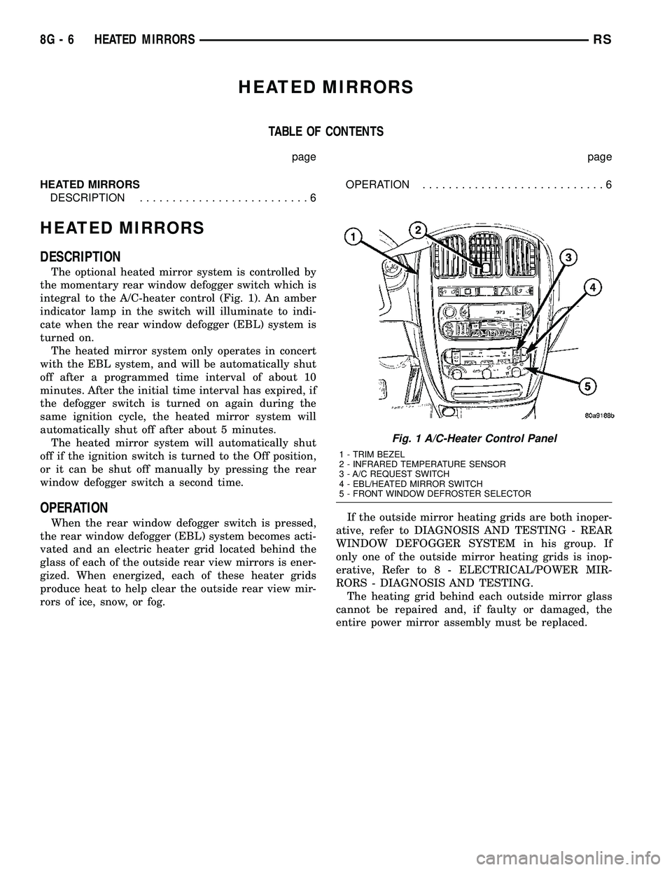
integral to the A/C-heater control (Fig. 1). An amber
indicator lamp in the switch will illuminate to indi-
cate when the rear window defogger (EBL) system is
turned on.
The heated mirror system only operates in concert
with the EBL system, and will be automatically shut
off after a programmed time interval of about 10
minutes. After the initial time interval has expired, if
the defogger switch is turned on again during the
same ignition cycle, the heated mirror system will
automatically shut off after about 5 minutes.
The heated mirror system will automatically shut
off if the ignition switch is turned to the Off position,
or it can be shut off manually by pressing the rear
window defogger switch a second time.
OPERATION
When the rear window defogger switch is pressed,
the rear window defogger (EBL) system becomes acti-
vated and an electric heater grid located behind the
glass of each of the outside rear view mirrors is ener-
gized. When energized, each of these heater grids
produce heat to help clear the outside rear view mir-
rors of ice, snow, or fog.If the outside mirror heating grids are both inoper-
ative, refer to DIAGNOSIS AND TESTING - REAR
WINDOW DEFOGGER SYSTEM in his group. If
only one of the outside mirror heating grids is inop-
erative, Refer to 8 - ELECTRICAL/POWER MIR-
RORS - DIAGNOSIS AND TESTING.
The heating grid behind each outside mirror glass
cannot be repaired and, if faulty or damaged, the
entire power mirror assembly must be replaced.
Fig. 1 A/C-Heater Control Panel
1 - TRIM BEZEL
2 - INFRARED TEMPERATURE SENSOR
3 - A/C REQUEST SWITCH
4 - EBL/HEATED MIRROR SWITCH
5 - FRONT WINDOW DEFROSTER SELECTOR
8G - 6 HEATED MIRRORSRS
Page 353 of 2339

Hard wired circuitry connects the heated seat sys-
tem components to each other through the electrical
system of the vehicle. These circuits may be con-
nected to each other, to the vehicle electrical system
and to the heated seat system components through
the use of a combination of soldered splices and
splice block connectors. Refer to the appropriate wir-
ing information for complete circuit schematic or con-
nector pin-out information.
OPERATION
The heated seat system components operate on
battery current received through a fuse in the Inte-
grated Power Module (IPM) on a fused ignition
switch output (run) circuit from the Body Control
Module (BCM). The system will only operate when
the ignition switch is in the On position. The heated
seat system will be turned Off automatically when-
ever the ignition switch is turned to any position
except On. Also, the heated seat system will not oper-
ate when the surface temperature of the seat cushion
cover at either heated seat sensor is above the
designed temperature set points of the system.
DIAGNOSIS AND TESTING
HEATED SEAT SYSTEM
The most efficient means of diagnosing the heated
seat system is by individual component. For diagno-
sis of a specific component refer to the following:
²Heated seat module, (Refer to 8 - ELECTRICAL/
ELECTRONIC CONTROL MODULES/MEMORY
HEATED SEAT/MIRROR MODULE - DIAGNOSIS
AND TESTING).
²Heated seat elements, (Refer to 8 - ELECTRI-
CAL/HEATED SEATS/HEATED SEAT ELEMENT -
DIAGNOSIS AND TESTING).
²Heated seat switch, (Refer to 8 - ELECTRICAL/
HEATED SEATS/DRIVER HEATED SEAT SWITCH
- DIAGNOSIS AND TESTING).
²Heated seat sensor, (Refer to 8 - ELECTRICAL/
HEATED SEATS/HEATED SEAT SENSOR - DIAG-
NOSIS AND TESTING).
Refer to the appropriate wiring information for
complete circuit schematic or connector pin-out infor-
mation.
HEATED SEAT SWITCH
DESCRIPTION
The heated seat switches are mounted in the
instrument panel center bezel (Fig. 2). The two three-
position rocker-type switches, one switch for each
front seat, are incorporated into one large switch
assembly that also includes the hazard, rear window
wiper and washer switches. Each heated seat switch
provides a resistor multiplexed signal to its respec-
tive Heated Seat Module (HSM) through separate
hard wired circuits. Each switch has an Off, Low,
and High position so that both the driver and the
front seat passenger can select a preferred seat heat-
ing mode. Each switch has two Light-Emitting
Diodes (LED) which light to indicate that the heater
for the seat is turned on.
The heated seat switches and their LEDs cannot
be repaired. If either switch or LED is faulty or dam-
aged, the entire switch assembly must be replaced.
Fig. 2 HEATED SEAT SWITCH LOCATION
1 - HEATED SEAT SWITCHES
8G - 8 HEATED SEAT SYSTEMRS
HEATED SEAT SYSTEM (Continued)
Page 375 of 2339
DIAGNOSIS AND TESTING
DIAGNOSIS AND TESTING - SELF-
DIAGNOSTICS
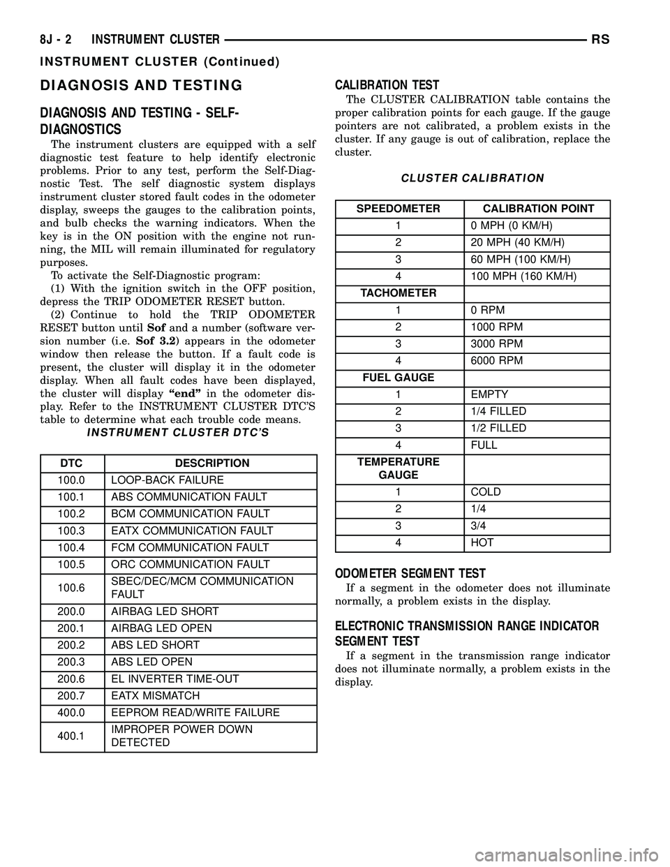
The instrument clusters are equipped with a self
diagnostic test feature to help identify electronic
problems. Prior to any test, perform the Self-Diag-
nostic Test. The self diagnostic system displays
instrument cluster stored fault codes in the odometer
display, sweeps the gauges to the calibration points,
and bulb checks the warning indicators. When the
key is in the ON position with the engine not run-
ning, the MIL will remain illuminated for regulatory
purposes.
To activate the Self-Diagnostic program:
(1) With the ignition switch in the OFF position,
depress the TRIP ODOMETER RESET button.
(2) Continue to hold the TRIP ODOMETER
RESET button untilSofand a number (software ver-
sion number (i.e.Sof 3.2) appears in the odometer
window then release the button. If a fault code is
present, the cluster will display it in the odometer
display. When all fault codes have been displayed,
the cluster will displayªendºin the odometer dis-
play. Refer to the INSTRUMENT CLUSTER DTC'S
table to determine what each trouble code means.
INSTRUMENT CLUSTER DTC'S
DTC DESCRIPTION
100.0 LOOP-BACK FAILURE
100.1 ABS COMMUNICATION FAULT
100.2 BCM COMMUNICATION FAULT
100.3 EATX COMMUNICATION FAULT
100.4 FCM COMMUNICATION FAULT
100.5 ORC COMMUNICATION FAULT
100.6SBEC/DEC/MCM COMMUNICATION
FAULT
200.0 AIRBAG LED SHORT
200.1 AIRBAG LED OPEN
200.2 ABS LED SHORT
200.3 ABS LED OPEN
200.6 EL INVERTER TIME-OUT
200.7 EATX MISMATCH
400.0 EEPROM READ/WRITE FAILURE
400.1IMPROPER POWER DOWN
DETECTED
CALIBRATION TEST
The CLUSTER CALIBRATION table contains the
proper calibration points for each gauge. If the gauge
pointers are not calibrated, a problem exists in the
cluster. If any gauge is out of calibration, replace the
cluster.
CLUSTER CALIBRATION
SPEEDOMETER CALIBRATION POINT
1 0 MPH (0 KM/H)
2 20 MPH (40 KM/H)
3 60 MPH (100 KM/H)
4 100 MPH (160 KM/H)
TACHOMETER
1 0 RPM
2 1000 RPM
3 3000 RPM
4 6000 RPM
FUEL GAUGE
1 EMPTY
2 1/4 FILLED
3 1/2 FILLED
4 FULL
TEMPERATURE
GAUGE
1 COLD
2 1/4
3 3/4
4 HOT
ODOMETER SEGMENT TEST
If a segment in the odometer does not illuminate
normally, a problem exists in the display.
ELECTRONIC TRANSMISSION RANGE INDICATOR
SEGMENT TEST
If a segment in the transmission range indicator
does not illuminate normally, a problem exists in the
display.
8J - 2 INSTRUMENT CLUSTERRS
INSTRUMENT CLUSTER (Continued)
Page 391 of 2339
(b) Install the switch in its bracket by aligning
the index tab on the switch with the slot in the
mounting bracket.
(c) When the switch is fully seated in its
bracket, rotate the switch clockwise approximately
30É to lock the switch into place.
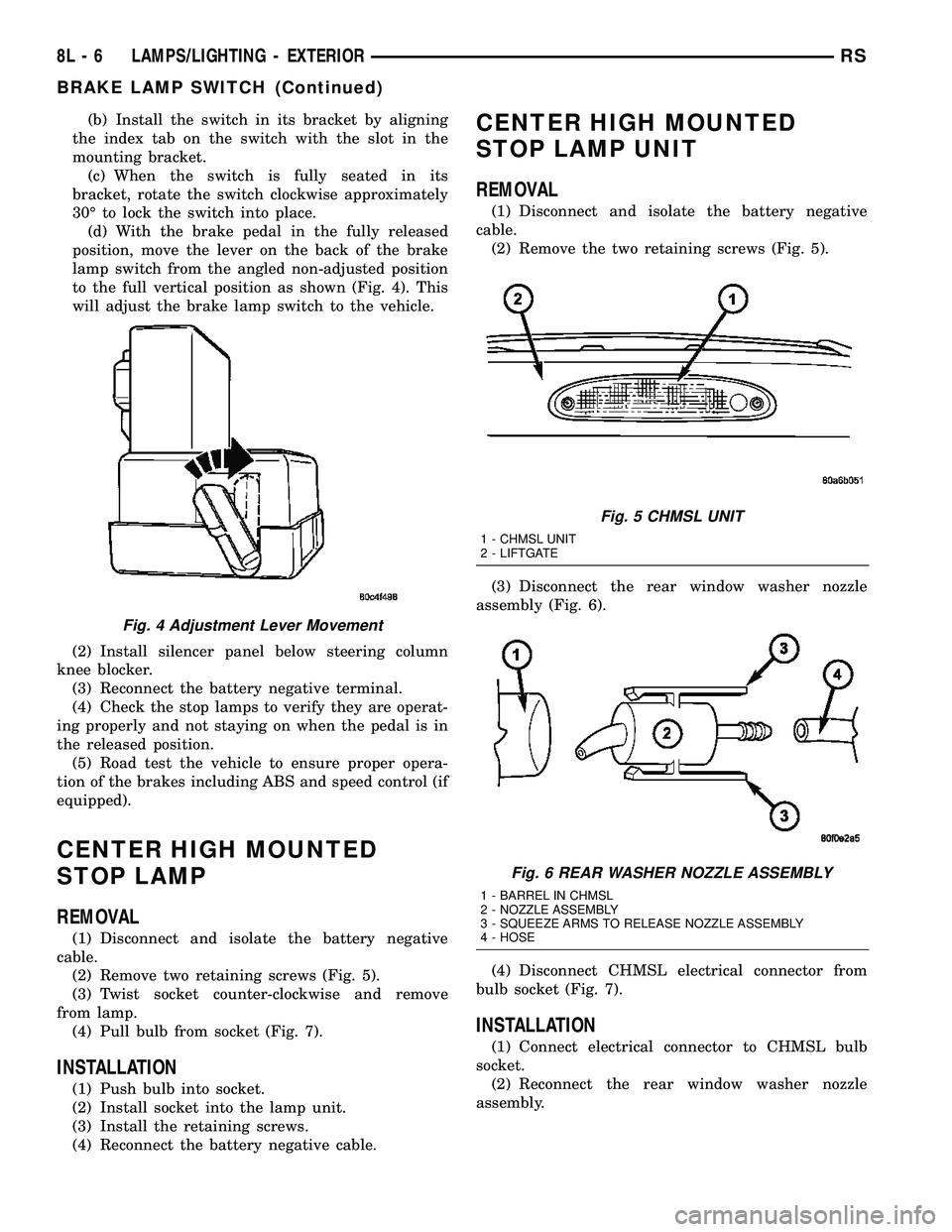
(d) With the brake pedal in the fully released
position, move the lever on the back of the brake
lamp switch from the angled non-adjusted position
to the full vertical position as shown (Fig. 4). This
will adjust the brake lamp switch to the vehicle.
(2) Install silencer panel below steering column
knee blocker.
(3) Reconnect the battery negative terminal.
(4) Check the stop lamps to verify they are operat-
ing properly and not staying on when the pedal is in
the released position.
(5) Road test the vehicle to ensure proper opera-
tion of the brakes including ABS and speed control (if
equipped).
CENTER HIGH MOUNTED
STOP LAMP
REMOVAL
(1) Disconnect and isolate the battery negative
cable.
(2) Remove two retaining screws (Fig. 5).
(3) Twist socket counter-clockwise and remove
from lamp.
(4) Pull bulb from socket (Fig. 7).
INSTALLATION
(1) Push bulb into socket.
(2) Install socket into the lamp unit.
(3) Install the retaining screws.
(4) Reconnect the battery negative cable.
CENTER HIGH MOUNTED
STOP LAMP UNIT
REMOVAL
(1) Disconnect and isolate the battery negative
cable.
(2) Remove the two retaining screws (Fig. 5).
(3) Disconnect the rear window washer nozzle
assembly (Fig. 6).
(4) Disconnect CHMSL electrical connector from
bulb socket (Fig. 7).
INSTALLATION
(1) Connect electrical connector to CHMSL bulb
socket.
(2) Reconnect the rear window washer nozzle
assembly.
Fig. 4 Adjustment Lever Movement
Fig. 5 CHMSL UNIT
1 - CHMSL UNIT
2 - LIFTGATE
Fig. 6 REAR WASHER NOZZLE ASSEMBLY
1 - BARREL IN CHMSL
2 - NOZZLE ASSEMBLY
3 - SQUEEZE ARMS TO RELEASE NOZZLE ASSEMBLY
4 - HOSE
8L - 6 LAMPS/LIGHTING - EXTERIORRS
BRAKE LAMP SWITCH (Continued)
Page 424 of 2339

POWER SYSTEMS
TABLE OF CONTENTS
page page
POWER LIFTGATE SYSTEM.................. 1
POWER LOCKS........................... 20
POWER MIRRORS........................ 26POWER SEAT SYSTEM..................... 31
POWER SLIDING DOOR SYSTEM............ 40
POWER WINDOWS........................ 61
POWER LIFTGATE SYSTEM
TABLE OF CONTENTS
page page
POWER LIFTGATE SYSTEM
DESCRIPTION..........................2
OPERATION............................2
DIAGNOSIS AND TESTING
POWER LIFTGATE SYSTEM..............3
STANDARD PROCEDURE
LIFTGATE ADJUSTMENT................8
POWER LIFTGATE LEARN CYCLE.........8
CHIME/THERMISTOR
DESCRIPTION..........................8
OPERATION............................8
REMOVAL.............................8
INSTALLATION..........................9
ENGAGE ACTUATOR
DESCRIPTION..........................9
OPERATION............................9
REMOVAL.............................9
INSTALLATION.........................10
EXTERIOR HANDLE SWITCH
DESCRIPTION.........................10
OPERATION...........................10
REMOVAL.............................10
INSTALLATION.........................10
FULL OPEN SWITCH
DESCRIPTION.........................11
OPERATION...........................11
REMOVAL.............................11
INSTALLATION.........................11
LATCH
DESCRIPTION.........................12OPERATION...........................12
REMOVAL.............................12
INSTALLATION.........................13
LATCH ACTUATOR
DESCRIPTION.........................13
OPERATION...........................13
REMOVAL.............................13
INSTALLATION.........................14
LIFTGATE MOTOR
DESCRIPTION.........................15
OPERATION...........................15
REMOVAL.............................15
INSTALLATION.........................16
LIFT GEAR & LINK ROD
DESCRIPTION.........................16
OPERATION...........................16
REMOVAL.............................16
INSTALLATION.........................17
PINCH SENSOR
DESCRIPTION.........................17
OPERATION...........................17
REMOVAL.............................18
INSTALLATION.........................18
TRANSVERSE BRACKET
DESCRIPTION.........................19
OPERATION...........................19
REMOVAL.............................19
INSTALLATION.........................19
RSPOWER SYSTEMS8N-1
Page 439 of 2339

INSTALLATION
(1) Using the motor housing tab, hook the liftgate
motor assembly on the D-pillar.
(2) Install the three motor assembly retaining
bolts. Torque the two rear most bolts first to 9.5 N´m
(85 in. lbs.). Torque the remaining bolt next to the
window actuator to 9.5 N´m (85 in. lbs.).
(3) Connect the liftgate motor assembly electrical
connector.
(4) Install the D-pillar trim panel on the vehicle,
(Refer to 23 - BODY/INTERIOR/LEFT D-PILLAR
TRIM PANEL - INSTALLATION).
(5) Connect the battery negative cable.
(6) Using an appropriate scan tool, check any
erase any power liftgate control module diagnostic
trouble codes related to the door motor assembly.
(7) Verify power liftgate system operation. Cycle
the power liftgate through one complete open and
close cycle, this will allow the power liftgate control
module to relearn its cycle with the new components.
LIFT GEAR & LINK ROD
DESCRIPTION
The lift gear and rod assembly are located in the
left rear of the vehicle and are visible without remov-ing the D-pillar trim (Fig. 16). The lift gear provides
the leverage to move the liftgate from the closed to
the open position. The lift gear attaches to a bearing
on the gear motor assembly with four bolts. On the
outboard side of the lift gear are riveted on teeth,
which mesh with the gear motor assembly drive
gears during a open or close operation. The rod
assembly is a steel shaft, equipped with two spheri-
cal rod ends which attaches the lift gear to the lift-
gate. The lift gear and rod assembly are serviceable
components.
OPERATION
One end of the rod assembly is attached to the lift-
gate, the other attached to the lift gear. When the lift
gear is driven by the gear motor assembly the lift-
gate is moved to the open or closed position.
REMOVAL
(1) Disconnect and isolate the battery negative
cable.
(2) Remove the left rear D-pillar trim panel from
the vehicle, (Refer to 23 - BODY/INTERIOR/LEFT
D-PILLAR TRIM PANEL - REMOVAL).
(3) Remove the lift gear retaining bolts (Fig. 17).
(4) Remove the lift gear and rod from the vehicle.
Fig. 16 LIFTGATE GEAR/MOTOR ASSEMBLY
1 - TRANSVERSE BRACKET
2 - ENGAGE ACTUATOR
3 - LIFT GEAR AND ROD ASSEMBLY
4 - LIFTGATE MOTOR
Fig. 17 LIFTGATE GEAR MOTOR ASSEMBLY
1 - ENGAGE ACTUATOR RETAINING SCREWS
2 - LIFT GEAR RETAINING BOLTS
8N - 16 POWER LIFTGATE SYSTEMRS
LIFTGATE MOTOR (Continued)
Page 442 of 2339

TRANSVERSE BRACKET
DESCRIPTION
The transverse bracket (Fig. 22) is used to support
and secure the power liftgate gear/motor assembly to
the left rear body D-pillar. The transverse bracket is
a serviceable power liftgate component.
OPERATION
The power liftgate transverse bracket supports the
gear motor assembly by supplying an additional
attachment point. Located on the leading edge of the
gear motor assembly, one end of the transverse
bracket attaches to the motor assembly the other to
the leading edge of the vehicles D-pillar.
REMOVAL
(1) Disconnect and isolate the battery negative
cable.
(2) Remove the left D-pillar trim from the vehicle,
(Refer to 23 - BODY/INTERIOR/LEFT D-PILLAR
TRIM PANEL - REMOVAL).
(3) Disconnect the gear motor assembly electrical
connector and disengage retaining pushpin.
(4) Loosen the gear motor assembly retaining bolts
to allow room for transverse bracket to be removed.
(5) Remove the transverse bracket retaining bolts
(Fig. 23).
(6)
Remove the transverse bracket from the vehicle.
INSTALLATION
(1) Position the transverse bracket in the vehicle.
Be certain the transverse bracket is properly posi-
tioned. The bracket should just touch the engage
actuator arm and be positioned between the actuator
arm and the motor housing.
(2) Torque the transverse bracket retaining bolts
to the gear motor assembly to 9.5 N´m (85 in. lbs.).
Do not tighten the transverse bracket retaining bolt,
located under the window actuator at this time.
(3) Torque the gear motor assembly retaining bolts
to 9.5 N´m (85 in. lbs.).
(4) Torque the final transverse bracket retaining
bolt to 9.5 N´m (85 in. lbs.).
(5) Connect the gear motor assembly electrical con-
nector and engage retaining pushpin.
(6) Install the left D-pillar trim, (Refer to 23 -
BODY/INTERIOR/LEFT D-PILLAR TRIM PANEL -
INSTALLATION).
(7) Connect the battery negative cable.
(8) Using an appropriate scan tool, check any
erase any power liftgate control module diagnostic
trouble codes related to the door motor assembly.
(9) Verify power liftgate system operation. Cycle
the power liftgate through one complete open and
close cycle, this will allow the power liftgate control
module to relearn its cycle with the new components.
Fig. 22 LIFTGATE GEAR/MOTOR ASSEMBLY
1 - TRANSVERSE BRACKET
2 - ENGAGE ACTUATOR
3 - LIFT GEAR AND ROD ASSEMBLY
4 - LIFTGATE MOTOR
Fig. 23 LIFTGATE GEAR MOTOR ASSEMBLY
1 - TRANSVERSE BRACKET
2 - ENGAGE ACTUATOR
3 - LIFT GEAR AND ROD ASSEMBLY
4 - LIFTGATE MOTOR
RSPOWER LIFTGATE SYSTEM8N-19
Page 445 of 2339
The lock function works from the RKE transmitter
even in an out of synchronization condition, therefore
it could be verified by pressing the LOCK button on
the RKE key fob.
DOOR CYLINDER LOCK
SWITCH - EXPORT
DESCRIPTION
The Door Cylinder Lock Switch (If equipped) is
used to:
²Unlock/Lock all the doors via the Central Lock-
ing feature.
²Arm/Disarm the Vehicle Theft Security System.
²Trigger the Illuminated Entry feature.
The door cylinder lock switch is mounted to the
rear of the driver door lock cylinder. When installed
on the rear of the cylinder, there is a tab on the lock
cylinder that aligns with the switch to prevent it
from turning. An anti-rotating device. The door cylin-
der lock switch is a one time use switch. Once it is
removed from the rear of the door lock cylinder, it
may not be reinstalled and a new switch must be
used.
OPERATION
When the Door Cylinder Lock Switch is turned
either way using the door key cylinder, the BCM
reads a direct message signal from the switch.
If turning the key cylinder once, toward the front
of the vehicle, this will:
(1) Mechanically unlock the door lock.
(2) Disarm the Vehicle Theft Security System (if
equipped).
(3) Turn on the Illuminated Entry (if equipped) for
approximately 30 seconds.
If the key cylinder is turned to the unlock position
(toward the front of vehicle) twice within two sec-
onds, all the doors and liftgate will unlock (if
equipped with the central locking feature).
To lock the vehicle using the door cylinder lock
switch, turn the key cylinder toward the rear of the
vehicle once. This will lock the door that you are
using the key on. If equipped with the central locking
feature, this will lock all the other doors and liftgate.
Furthermore, this will arm the vehicle theft security
system and turn off the illuminated entry.
DIAGNOSIS AND TESTING
DOOR CYLINDER LOCK SWITCH - EXPORT
Any diagnosis of the power lock system
should begin with the use of the DRB IIItdiag-
nostic tool. For information on the use of theDRB IIIt, refer to the appropriate Diagnostic
Service Manual.
For complete circuit diagrams, refer to the appro-
priate wiring information.
(1) Visually inspect the switch for proper installa-
tion. Make sure it is seated on the rear of the key
cylinder, with the tab of the door key cylinder prop-
erly aligned with the slot on the door cylinder lock
switch.
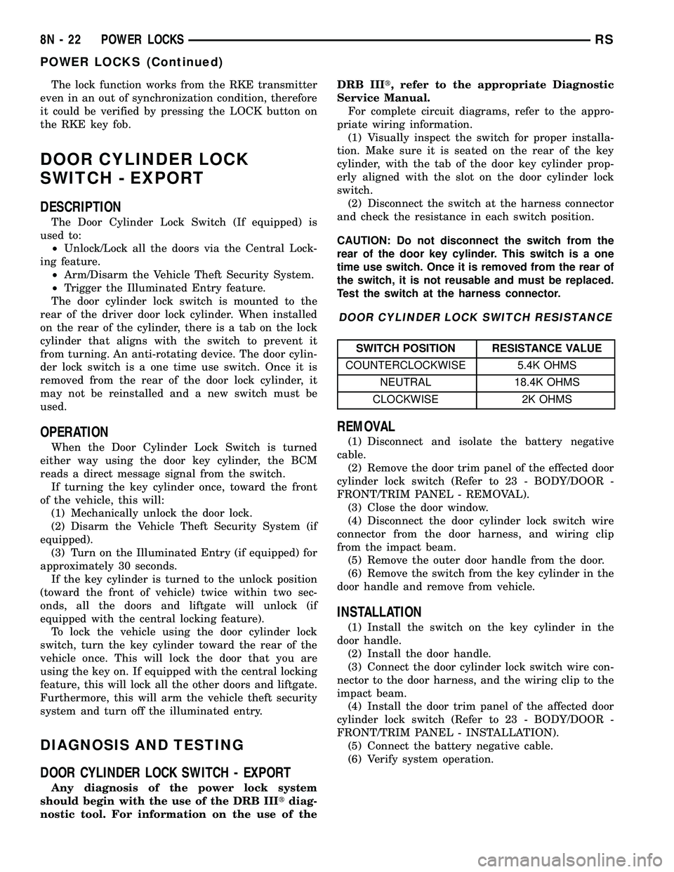
(2) Disconnect the switch at the harness connector
and check the resistance in each switch position.
CAUTION: Do not disconnect the switch from the
rear of the door key cylinder. This switch is a one
time use switch. Once it is removed from the rear of
the switch, it is not reusable and must be replaced.
Test the switch at the harness connector.
DOOR CYLINDER LOCK SWITCH RESISTANCE
SWITCH POSITION RESISTANCE VALUE
COUNTERCLOCKWISE 5.4K OHMS
NEUTRAL 18.4K OHMS
CLOCKWISE 2K OHMS
REMOVAL
(1) Disconnect and isolate the battery negative
cable.
(2) Remove the door trim panel of the effected door
cylinder lock switch (Refer to 23 - BODY/DOOR -
FRONT/TRIM PANEL - REMOVAL).
(3) Close the door window.
(4) Disconnect the door cylinder lock switch wire
connector from the door harness, and wiring clip
from the impact beam.
(5) Remove the outer door handle from the door.
(6) Remove the switch from the key cylinder in the
door handle and remove from vehicle.
INSTALLATION
(1) Install the switch on the key cylinder in the
door handle.
(2) Install the door handle.
(3) Connect the door cylinder lock switch wire con-
nector to the door harness, and the wiring clip to the
impact beam.
(4) Install the door trim panel of the affected door
cylinder lock switch (Refer to 23 - BODY/DOOR -
FRONT/TRIM PANEL - INSTALLATION).
(5) Connect the battery negative cable.
(6) Verify system operation.
8N - 22 POWER LOCKSRS
POWER LOCKS (Continued)
Page 451 of 2339
AUTOMATIC DAY / NIGHT
MIRROR
DESCRIPTION
An automatic dimming inside day/night rear view
mirror and an automatic dimming driver side outside
rear view mirror are available factory-installed
options on this model. Following is a general descrip-
tion of this optional equipment.
The automatic day/night mirror is able to automat-
ically change its reflectance. A thin layer of electro-
chromic material between two pieces of conductive
glass make up the face of the mirror. Two photocell
sensors are used to monitor light levels and adjust
the reflectance of the mirror to reduce the glare of
headlamps approaching the vehicle from the rear.
For removal procedures, (Refer to 23 - BODY/IN-
TERIOR/REAR VIEW MIRROR - REMOVAL).
OPERATION
The ambient photocell sensor faces forward, to
detect the outside light levels. A second sensor faces
rearward to detect the light level received through
the vehicles back window. When the difference
between the two light levels becomes too great (the
light level received at the rear of the mirror is much
higher than that at the front of the mirror), the mir-
ror begins to darken.
The mirror switch allows the driver a manual con-
trol of whether the automatic dimming feature is
operational. When AUTO is selected a small Light-
Emitting Diode (LED), to the right of the mirror
switch, is illuminated. The automatic dimming fea-
ture will only operate when the ignition switch is in
the On position. The mirror also senses the backup
lamp circuit, and will automatically disable its self-
dimming feature whenever the transmission gear
selector is in the Reverse position.
NOTE: The mirror always defaults to an ON state
upon ignition.
The driver side automatic dimming mirror is stan-
dard with the automatic dimming inside mirror. The
signal to control the dimming of that mirror is gen-
erated by the automatic day/night inside rear view
mirror circuitry. That signal is then delivered to the
driver side outside rear view mirror on a hard wired
circuit.
The automatic day/night mirror cannot be
repaired. If faulty or damaged, the entire inside rear
view mirror assembly must be replaced.
DIAGNOSIS AND TESTING
AUTOMATIC DAY / NIGHT MIRROR
For circuit descriptions and diagrams, refer to the
appropriate wiring information. The wiring informa-
tion includes wiring diagrams, proper wire and con-
nector repair procedures, details of wire harness
routing and retention, connector pin-out information
and location views for the various wire harness con-
nectors, splices and grounds.
(1) Check the fuse in the intelligent power module.
If OK, go to Step 2. If not OK, repair the shorted cir-
cuit or component as required and replace the faulty
fuse.
(2) Turn the ignition switch to the On position.
Check for battery voltage at the fuse in the intelli-
gent power module. If OK, go to Step 3. If not OK,
repair the open circuit to the ignition switch as
required.
(3) Unplug the wire harness connector from the
automatic day/night mirror. Check for battery voltage
at the fused ignition switch output circuit cavity of
the automatic day/night mirror wire harness connec-
tor. If OK, go to Step 4. If not OK, repair the open
circuit to the junction block as required.
(4) Turn the ignition switch to the Off position.
Check for continuity between the ground circuit cav-
ity of the automatic day/night mirror wire harness
connector and a good ground. There should be conti-
nuity. If OK, go to Step 5. If not OK, repair the cir-
cuit to ground as required.
(5) Turn the ignition switch to the On position. Set
the parking brake. Place the transmission gear selec-
tor lever in the Reverse position. Check for battery
voltage at the backup lamp switch output circuit cav-
ity of the automatic day/night mirror wire harness
connector. If voltage is present, reinstall the auto-
matic day/night mirror wire harness connector and
go to Step 6. If not OK, repair the open circuit as
required.
(6) Place the transmission gear selector lever in
the Neutral position. Place the automatic day/night
mirror switch in the On (LED in the switch is
lighted) position. Cover the forward facing ambient
photocell sensor to keep out any ambient light.
NOTE: The ambient photocell sensor must be cov-
ered completely, so that no light reaches the sen-
sor. Use a finger pressed tightly against the sensor,
or cover the sensor completely with electrical tape.
(7) Shine a light into the rearward facing head-
lamp photocell sensor. The automatic day/night mir-
ror should darken. The automatic day/night mirror
should darken within 2 minutes if testing for the
first time. For immediate response, turn the vehicle
8N - 28 POWER MIRRORSRS