window CHRYSLER VOYAGER 2005 Service Manual
[x] Cancel search | Manufacturer: CHRYSLER, Model Year: 2005, Model line: VOYAGER, Model: CHRYSLER VOYAGER 2005Pages: 2339, PDF Size: 59.69 MB
Page 6 of 2339
FASTENER USAGE
DESCRIPTION
FASTENER USAGE
WARNING: USE OF AN INCORRECT FASTENER
MAY RESULT IN COMPONENT DAMAGE OR PER-
SONAL INJURY.
Fasteners and torque specifications references in
this Service Manual are identified in metric and SAE
format.
During any maintenance or repair procedures, it is
important to salvage all fasteners (nuts, bolts, etc.)
for reassembly. If the fastener is not salvageable, a
fastener of equivalent specification must be used.
THREADED HOLE REPAIR
Most stripped threaded holes can be repaired using
a Helicoilt. Follow the vehicle or Helicoiltrecommen-
dations for application and repair procedures.
INTERNATIONAL SYMBOLS
DESCRIPTION
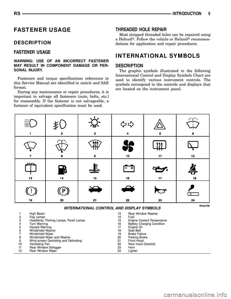
The graphic symbols illustrated in the following
International Control and Display Symbols Chart are
used to identify various instrument controls. The
symbols correspond to the controls and displays that
are located on the instrument panel.
INTERNATIONAL CONTROL AND DISPLAY SYMBOLS
1 High Beam 13 Rear Window Washer
2 Fog Lamps 14 Fuel
3 Headlamp, Parking Lamps, Panel Lamps 15 Engine Coolant Temperature
4 Turn Warning 16 Battery Charging Condition
5 Hazard Warning 17 Engine Oil
6 Windshield Washer 18 Seat Belt
7 Windshield Wiper 19 Brake Failure
8 Windshield Wiper and Washer 20 Parking Brake
9 Wind screen Demisting and Defrosting 21 Front Hood
10 Ventilating Fan 22 Rear hood (Decklid)
11 Rear Window Defogger 23 Horn
12 Rear Window Wiper 24 Lighter
RSINTRODUCTION5
Page 269 of 2339
ANTENNA MODULE - EXPORT
DESCRIPTION
The antenna module is an electromagnetic circuit
component designed to capture and enhance RF
(Radio Frequency) signals in both the AM and FM
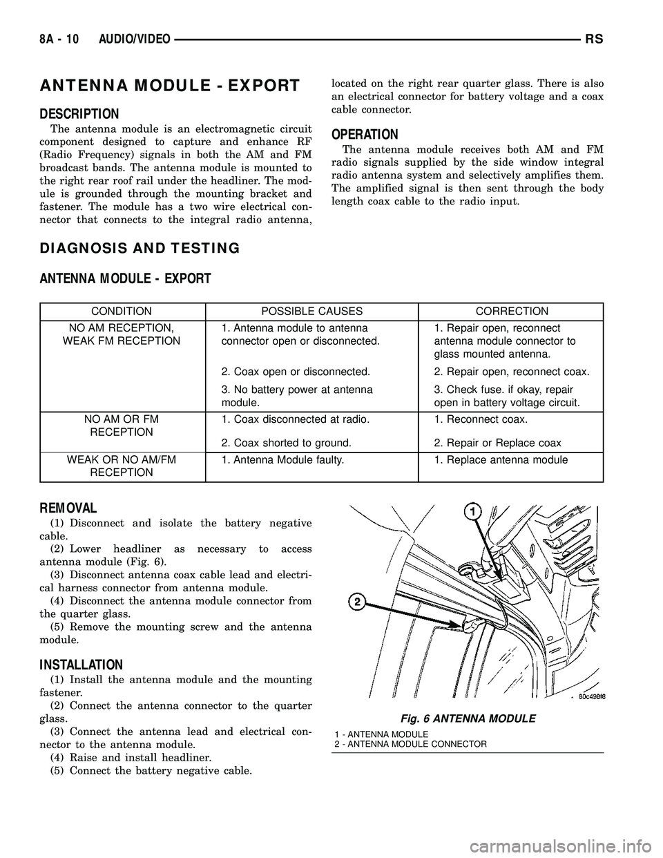
broadcast bands. The antenna module is mounted to
the right rear roof rail under the headliner. The mod-
ule is grounded through the mounting bracket and
fastener. The module has a two wire electrical con-
nector that connects to the integral radio antenna,located on the right rear quarter glass. There is also
an electrical connector for battery voltage and a coax
cable connector.OPERATION
The antenna module receives both AM and FM
radio signals supplied by the side window integral
radio antenna system and selectively amplifies them.
The amplified signal is then sent through the body
length coax cable to the radio input.
DIAGNOSIS AND TESTING
ANTENNA MODULE - EXPORT
CONDITION POSSIBLE CAUSES CORRECTION
NO AM RECEPTION,
WEAK FM RECEPTION1. Antenna module to antenna
connector open or disconnected.1. Repair open, reconnect
antenna module connector to
glass mounted antenna.
2. Coax open or disconnected. 2. Repair open, reconnect coax.
3. No battery power at antenna
module.3. Check fuse. if okay, repair
open in battery voltage circuit.
NO AM OR FM
RECEPTION1. Coax disconnected at radio. 1. Reconnect coax.
2. Coax shorted to ground. 2. Repair or Replace coax
WEAK OR NO AM/FM
RECEPTION1. Antenna Module faulty. 1. Replace antenna module
REMOVAL
(1) Disconnect and isolate the battery negative
cable.
(2) Lower headliner as necessary to access
antenna module (Fig. 6).
(3) Disconnect antenna coax cable lead and electri-
cal harness connector from antenna module.
(4) Disconnect the antenna module connector from
the quarter glass.
(5) Remove the mounting screw and the antenna
module.
INSTALLATION
(1) Install the antenna module and the mounting
fastener.
(2) Connect the antenna connector to the quarter
glass.
(3) Connect the antenna lead and electrical con-
nector to the antenna module.
(4) Raise and install headliner.
(5) Connect the battery negative cable.
Fig. 6 ANTENNA MODULE
1 - ANTENNA MODULE
2 - ANTENNA MODULE CONNECTOR
8A - 10 AUDIO/VIDEORS
Page 272 of 2339
(6) Install glove box (Refer to 23 - BODY/INSTRU-
MENT PANEL/GLOVE BOX - INSTALLATION).
(7) Connect the battery negative cable.
QUARTER GLASS INTEGRAL
ANTENNA - EXPORT
DESCRIPTION
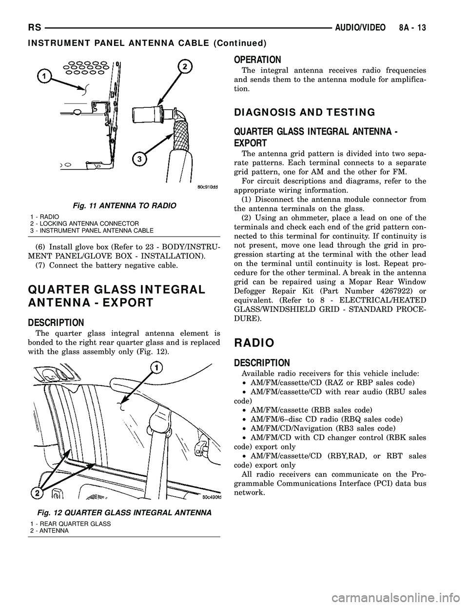
The quarter glass integral antenna element is
bonded to the right rear quarter glass and is replaced
with the glass assembly only (Fig. 12).
OPERATION
The integral antenna receives radio frequencies
and sends them to the antenna module for amplifica-
tion.
DIAGNOSIS AND TESTING
QUARTER GLASS INTEGRAL ANTENNA -
EXPORT
The antenna grid pattern is divided into two sepa-
rate patterns. Each terminal connects to a separate
grid pattern, one for AM and the other for FM.
For circuit descriptions and diagrams, refer to the
appropriate wiring information.
(1) Disconnect the antenna module connector from
the antenna terminals on the glass.
(2) Using an ohmmeter, place a lead on one of the
terminals and check each end of the grid pattern con-
nected to this terminal for continuity. If continuity is
not present, move one lead through the grid in pro-
gression starting at the terminal with the other lead
on the terminal until continuity is lost. Repeat pro-
cedure for the other terminal. A break in the antenna
grid can be repaired using a Mopar Rear Window
Defogger Repair Kit (Part Number 4267922) or
equivalent. (Refer to 8 - ELECTRICAL/HEATED
GLASS/WINDSHIELD GRID - STANDARD PROCE-
DURE).
RADIO
DESCRIPTION
Available radio receivers for this vehicle include:
²AM/FM/cassette/CD (RAZ or RBP sales code)
²AM/FM/cassette/CD with rear audio (RBU sales
code)
²AM/FM/cassette (RBB sales code)
²AM/FM/6±disc CD radio (RBQ sales code)
²AM/FM/CD/Navigation (RB3 sales code)
²AM/FM/CD with CD changer control (RBK sales
code) export only
²AM/FM/cassette/CD (RBY,RAD, or RBT sales
code) export only
All radio receivers can communicate on the Pro-
grammable Communications Interface (PCI) data bus
network.
Fig. 11 ANTENNA TO RADIO
1 - RADIO
2 - LOCKING ANTENNA CONNECTOR
3 - INSTRUMENT PANEL ANTENNA CABLE
Fig. 12 QUARTER GLASS INTEGRAL ANTENNA
1 - REAR QUARTER GLASS
2 - ANTENNA
RSAUDIO/VIDEO8A-13
INSTRUMENT PANEL ANTENNA CABLE (Continued)
Page 281 of 2339
PARK ASSIST SYSTEM
The Park Assist System display activates an audi-
ble tone that changes from intermittent to continu-
ous as the final two Light Emitting Diodes (LED's)
are illuminated on one side or both sides of the dis-
play.
The system detection length from the rear of the
vehicle is 0.3 meters to 1.5 meters. This area extends
around the rear side of the vehicle. The system detec-
tion height from the ground is 0.2 meters to about
1.5 meters. The radio mutes when the system acti-
vates its audible tone.
When the driver selects Reverse the system scans
for objects behind the vehicle using four sensors
located in the rear bumper. A warning display above
the rear window provides both visible and audible
warnings indicating the range of the object.
The system is active only when the transmission
gear selector is in reverse for vehicle speeds less than
16 Km/h (10 mph). If the vehicle's Parking/Emer-
gency Brake is applied, the system is deactivated.
The display contains two sets of yellow and red
Light Emitting Diode's (LED's) that the driver can
see as they look over their shoulder while backing
up. Each side of the vehicle has its own warning
LED's. The system provides a visual warning by illu-
minating one or more yellow LED's as the vehicle
gets closer to the object. As the vehicle continues to
approach the object, one red LED is illuminated and
the system emits a series of short beeps. The tone
will remain constant and both red LED's are illumi-
nated once the vehicle is within 12 inches (30.5 cm)
of the object.
The system can be turned ON or OFF through the
Electronic Vehicle Information Center (EVIC) when
the vehicle is in PARK. If the park assist system is
turned OFF, a single chime will sound and the EVIC
will display the following message ªREAR PARK
ASSIST OFFº, when the vehicle is in reverse.
²Ensure that the rear bumper is free of dirt and
debris to keep the system operating properly.
²Jackhammers, large trucks, and other vibrations
could affect the performance of the system.
²Ensure that the parking brake is not applied.
If ªService Park Assist Systemº appears in the
EVIC after making sure the rear bumper is clean,
proceed to diagnose the system using a scan tool and
the appropriate diagnostic information.
WARNING
On vehicles equipped with airbags, disable
the airbag system before attempting any steer-
ing wheel, steering column, or instrument
panel component diagnosis or service. Discon-
nect and isolate the battery negative (ground)
cable, then wait two minutes for the airbag sys-
tem capacitor to discharge before performing
further diagnosis or service. This is the only
sure way to disable the airbag system. Failure
to take the proper precautions could result in
accidental airbag deployment, personal injury,
or death.
DIAGNOSIS AND TESTING - CHIME SYSTEM
Refer to the proper Body Diagnostic Procedures
manual for complete Diagnosis and Testing of the
Chime System.
NO TONE WHEN IGNITION SWITCH IS TURNED ON
AND DRIVER'S SEAT BELT IS NOT BUCKLED.
(1) Using a DRB llltscan tool, actuate chime
(BCM actuates).
(2) Using a voltmeter, check for voltage:
(a) BCM has two battery feeds at pin 1 and pin
5 of the 6±way connector.
(b) Pin 5 of the (BX2) 32 way connector of the
BCM for ignition feed.
(c) Check voltage (PX2) connector, pin 34 for 12v.
(d) If voltage OK, go to step Step 3
(e) If NO voltage repair as necessary. Refer to
the appropriate wiring information. The wiring
information includes wiring diagrams, proper wire
and connector repair procedures, further details on
wire harness routing and retention, as well as pin-
out and location views for the various wire harness
connectors, splices and grounds.
(3) Check drivers seat belt buckle switch input
(from Occupant Restraint Controller (ORC) for a
closed circuit when not buckled. If input not seen,
look for open in wiring or switch. The switch is
grounded when belt is not buckled.
(4) Verify Programmable Communication Interface
(PCI) data bus communication between ORC and
BCM.
8B - 2 CHIME/BUZZERRS
CHIME/BUZZER (Continued)
Page 282 of 2339
NO FASTEN SEAT BELT LAMP WHEN IGNITION
SWITCH IS TURNED ON.
(1) Check for burned out lamp.
(2) Using a voltmeter check for voltage at the clus-
ter connector:
(a) Pin 2 of the mechanical instrument cluster
for battery feed.
(b) Pin 11 of the mechanical instrument cluster
for ignition voltage.
(3) Repair as necessary.
FASTEN SEAT BELT LAMP OR TONE CONTINUES
FOR MORE THAN 10 SECONDS AFTER SEAT
BELTS ARE FASTENED AND DRIVER'S DOOR IS
CLOSED.
Refer to the proper Body Diagnostic Procedures
manual.
NO TONE WHEN PARK OR HEADLAMPS ARE ON
AND DRIVER'S DOOR IS OPEN.
Make sure ignition is in lock position with the key
removed.
(1) Check the BCM DTC's and BCM sensors to
verify the door is open. Repair as necessary.
(2) Actuate Chime (BCM actuates).
(3) Inspect BCM connectors and wires for proper
connection.
(4) Measure with a voltmeter the voltage (12v) on
BCM connector (PX2) pin 34 with harness connected.
(5) Check BCM sensors to verify headlamp switch
position.
PARK ASSIST DISPLAY
DESCRIPTION
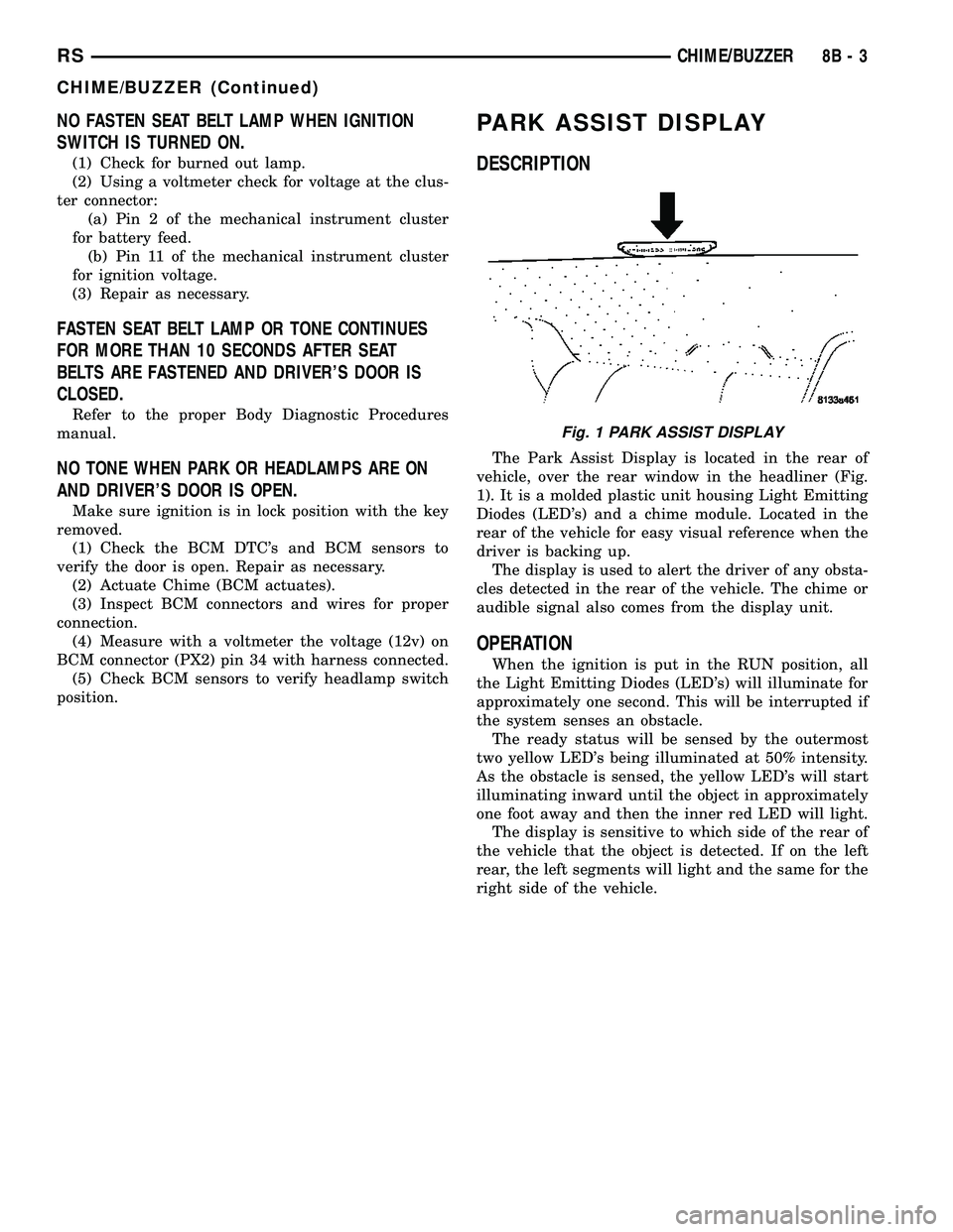
The Park Assist Display is located in the rear of
vehicle, over the rear window in the headliner (Fig.
1). It is a molded plastic unit housing Light Emitting
Diodes (LED's) and a chime module. Located in the
rear of the vehicle for easy visual reference when the
driver is backing up.
The display is used to alert the driver of any obsta-
cles detected in the rear of the vehicle. The chime or
audible signal also comes from the display unit.
OPERATION
When the ignition is put in the RUN position, all
the Light Emitting Diodes (LED's) will illuminate for
approximately one second. This will be interrupted if
the system senses an obstacle.
The ready status will be sensed by the outermost
two yellow LED's being illuminated at 50% intensity.
As the obstacle is sensed, the yellow LED's will start
illuminating inward until the object in approximately
one foot away and then the inner red LED will light.
The display is sensitive to which side of the rear of
the vehicle that the object is detected. If on the left
rear, the left segments will light and the same for the
right side of the vehicle.
Fig. 1 PARK ASSIST DISPLAY
RSCHIME/BUZZER8B-3
CHIME/BUZZER (Continued)
Page 284 of 2339
²System diagnostics - diagnosis and error han-
dling (sensors, display, module).
²Data exchange over the Programmable Commu-
nication Interface (PCI) data bus.
OPERATION
The module has a number of functions:
²Supply voltage to the sensors and display.
²Disconnection of the display with bus idle and
over voltage Vmax.
²Triggering the sensors.
²Analyze echo delay times and calculate obstacle
distances.
²Bi-directional data communication to the display
for diagnosis.
²System diagnostics - diagnosis and error han-
dling (sensors, display, module).
²Data exchange over the Programmable Commu-
nication Interface (PCI) data bus.
The system detection length from the rear of the
vehicle is 0.3 meters to 1.5 meters. This area extends
around the rear side of the vehicle. The system detec-
tion height from the ground is 0.2 meters to about
1.5 meters. The radio mutes when the system acti-
vates its audible tone.When the driver selects Reverse, the system scans
for objects behind the vehicle using four sensors
located in the rear bumper. Objects can be detected
from up to 1.5 meters. A warning display above the
rear window provides both visible and audible warn-
ings indicating the range of the object.
The system is active only when the vehicle is in
reverse for vehicle speeds less than 16 Km/h (10
mph). If the vehicles Parking/Emergency Brake is
applied, the system is deactivated.
The display contains two sets of yellow and red
Light Emitting Diode's (LED's) that the driver can
see as they look over their shoulder while backing
up. Each side of the vehicle has its own warning
LED's. The system provides a visual warning by illu-
minating one or more yellow LED's as the vehicle
gets closer to the object. As the vehicle continues to
approaches the object, one red LED is illuminated
and the system emits a series of short beeps. The
tone will remain constant and both red LED's are
illuminated once the vehicle is within 12 inches (30.5
cm) of the object.
The system can be turned ON or OFF through the
Electronic Vehicle Information Center (EVIC) when
the vehicle is in PARK. If the park assist system is
turned OFF, a single chime will sound and the EVIC
will display the following message ªREAR PARK
ASSIST OFFº, when the vehicle is in reverse.
²Ensure that the rear bumper is free of dirt and
debris to keep the system operating properly.
²Jackhammers, large trucks, and other vibrations
could affect the performance of the system.
²Ensure that the parking brake is not applied.
If ªService Park Assist Systemº appears in the
EVIC after making sure the rear bumper is clean,
proceed to diagnose the system using a scan tool and
the appropriate diagnostic information.
To diagnose the Park Assist Module, use a scan
tool and the appropriate body diagnostic information.
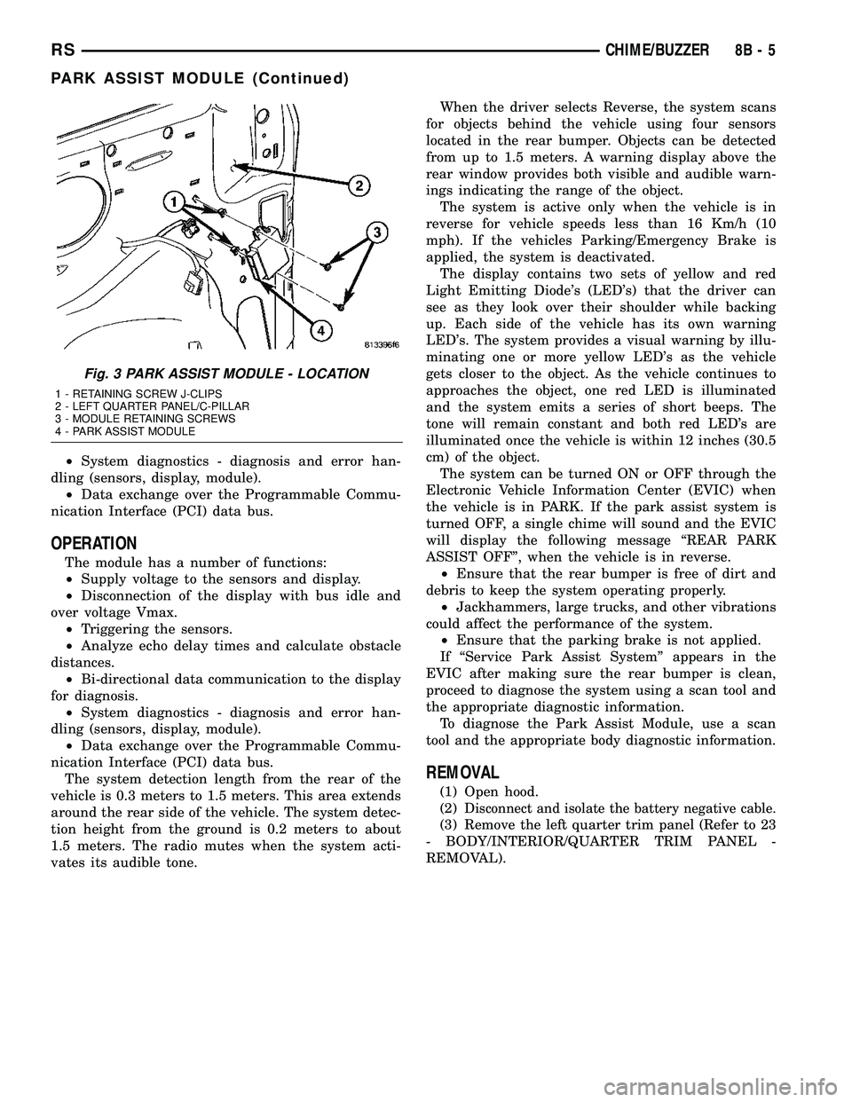
REMOVAL
(1) Open hood.
(2)
Disconnect and isolate the battery negative cable.
(3) Remove the left quarter trim panel (Refer to 23
- BODY/INTERIOR/QUARTER TRIM PANEL -
REMOVAL).
Fig. 3 PARK ASSIST MODULE - LOCATION
1 - RETAINING SCREW J-CLIPS
2 - LEFT QUARTER PANEL/C-PILLAR
3 - MODULE RETAINING SCREWS
4 - PARK ASSIST MODULE
RSCHIME/BUZZER8B-5
PARK ASSIST MODULE (Continued)
Page 346 of 2339
HEATED SYSTEMS
TABLE OF CONTENTS
page page
HEATED GLASS........................... 1
HEATED MIRRORS......................... 6HEATED SEAT SYSTEM..................... 7
HEATED GLASS
TABLE OF CONTENTS
page page
HEATED GLASS
DESCRIPTION..........................1
OPERATION............................2
DIAGNOSIS AND TESTING
ELECTRIC BACKLIGHT (EBL) SYSTEM.....2
REAR WINDOW DEFOGGER RELAY
DESCRIPTION..........................3
OPERATION............................3REMOVAL.............................4
INSTALLATION..........................4
REAR WINDOW DEFOGGER SWITCH
DESCRIPTION..........................4
OPERATION............................4
REAR WINDOW DEFOGGER GRID
STANDARD PROCEDURE
GRID REPAIR PROCEDURE..............5
HEATED GLASS
DESCRIPTION
CAUTION: Grid lines can be damaged or scraped
off with sharp instruments. Care should be taken in
cleaning glass or removing foreign materials,
decals or stickers. Normal glass cleaning solvents
or hot water used with rags or toweling is recom-
mended.
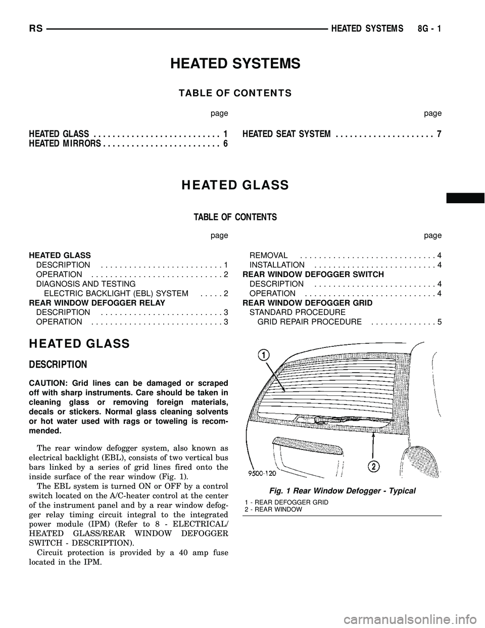
The rear window defogger system, also known as
electrical backlight (EBL), consists of two vertical bus
bars linked by a series of grid lines fired onto the
inside surface of the rear window (Fig. 1).
The EBL system is turned ON or OFF by a control
switch located on the A/C-heater control at the center
of the instrument panel and by a rear window defog-
ger relay timing circuit integral to the integrated
power module (IPM) (Refer to 8 - ELECTRICAL/
HEATED GLASS/REAR WINDOW DEFOGGER
SWITCH - DESCRIPTION).
Circuit protection is provided by a 40 amp fuse
located in the IPM.
Fig. 1 Rear Window Defogger - Typical
1 - REAR DEFOGGER GRID
2 - REAR WINDOW
RSHEATED SYSTEMS8G-1
Page 347 of 2339
OPERATION
When the rear window defogger button is
depressed to the On position, current is directed to
the rear defogger grid lines and the heated power
mirrors (if equipped). The heated grid lines heat the
glass to help clear the rear window and side mirror
surfaces of fog or frost.
The electric backlight (EBL) system is controlled
by a momentary switch located in the A/C-heater
control on the instrument panel. A yellow indicator in
the switch will illuminate to indicate when the sys-
tem is turned on. The integrated power module (IPM)
contains the EBL system control circuitry.
NOTE: The rear window defogger turns off automat-
ically after approximately 10 minutes of initial oper-
ation. Each following activation cycle of the
defogger system will last approximately five min-
utes.
The EBL system will be automatically turned off
after a programmed time interval of about ten min-
utes. After the initial time interval has expired, if the
defogger switch is turned on again during the same
ignition cycle, the defogger system will automatically
turn off after about five minutes.
The EBL system will automatically shut off if the
ignition switch is turned to the Off position, or it can
be turned off manually by depressing the defogger
switch a second time.
DIAGNOSIS AND TESTING
ELECTRIC BACKLIGHT (EBL) SYSTEM
NOTE: Illumination of the defogger switch indicator
lamp means that there is electrical current available
at the output of the rear window defogger logic cir-
cuitry, but does not confirm that the electrical cur-
rent is reaching the rear glass heating grid lines.
NOTE: For circuit descriptions and diagrams of the
rear window defogger system, refer to 8W - WIRING
DIAGRAM INFORMATION.
Operation of the electrical backlight (EBL) system
can be confirmed by the following:(1) Turn the ignition switch to the On position. Set
the defogger switch in the On position. The rear win-
dow defogger operation can be checked by feeling the
rear window glass. A distinct difference in tempera-
ture between the grid lines and the adjacent clear
glass can be detected within three to four minutes of
operation.
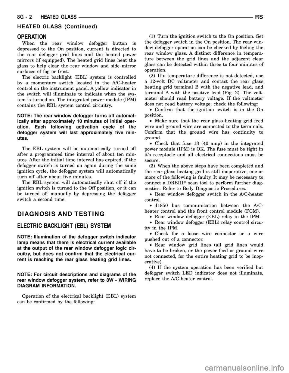
(2) If a temperature difference is not detected, use
a 12-volt DC voltmeter and contact the rear glass
heating grid terminal B with the negative lead, and
terminal A with the positive lead (Fig. 2). The volt-
meter should read battery voltage. If the voltmeter
does not read battery voltage, check the following:
²Confirm that the ignition switch is in the On
position.
²Make sure that the rear glass heating grid feed
wire and ground wire are connected to the terminals.
Confirm that the ground wire has continuity to
ground.
²Check that fuse 13 (40 amp) in the integrated
power module (IPM) is OK. The fuse must be tight in
it's receptacle and all electrical connections must be
secure.
(3) When the above steps have been completed and
the rear glass heating grid is still inoperative, one or
more of the following is faulty. It may be necessary to
connect a DRBIIItscan tool to perform further diag-
nostics. Refer to Body Diagnostic Procedures.
²Rear window defogger switch in the A/C-heater
control.
²J1850 bus communication between the A/C-
heater control and the front control module (FCM).
²Rear window defogger (EBL) relay in the IPM.
²Rear window defogger (EBL) relay control circu-
ity in the IPM.
²Check for a loose wire connector or a wire
pushed out of a connector.
²Rear window grid lines (all grid lines would
have to be broken, or the power feed or ground wire
not connected, for the entire heating grid to be inop-
erative).
(4) If the system operation has been verified but
defogger switch LED indicator does not illuminate,
replace the A/C-heater control.
8G - 2 HEATED GLASSRS
HEATED GLASS (Continued)
Page 348 of 2339
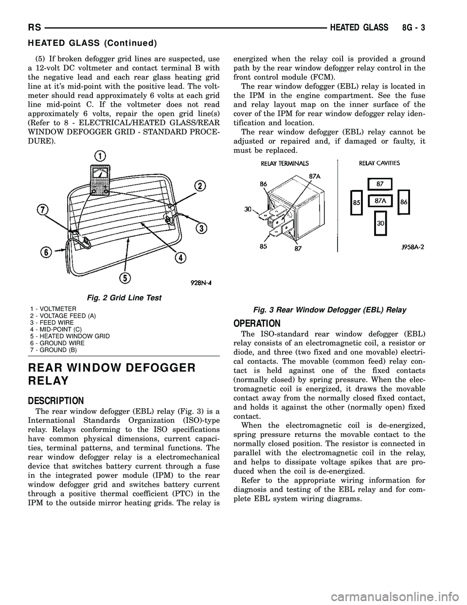
(5) If broken defogger grid lines are suspected, use
a 12-volt DC voltmeter and contact terminal B with
the negative lead and each rear glass heating grid
line at it's mid-point with the positive lead. The volt-
meter should read approximately 6 volts at each grid
line mid-point C. If the voltmeter does not read
approximately 6 volts, repair the open grid line(s)
(Refer to 8 - ELECTRICAL/HEATED GLASS/REAR
WINDOW DEFOGGER GRID - STANDARD PROCE-
DURE).
REAR WINDOW DEFOGGER
RELAY
DESCRIPTION
The rear window defogger (EBL) relay (Fig. 3) is a
International Standards Organization (ISO)-type
relay. Relays conforming to the ISO specifications
have common physical dimensions, current capaci-
ties, terminal patterns, and terminal functions. The
rear window defogger relay is a electromechanical
device that switches battery current through a fuse
in the integrated power module (IPM) to the rear
window defogger grid and switches battery current
through a positive thermal coefficient (PTC) in the
IPM to the outside mirror heating grids. The relay isenergized when the relay coil is provided a ground
path by the rear window defogger relay control in the
front control module (FCM).
The rear window defogger (EBL) relay is located in
the IPM in the engine compartment. See the fuse
and relay layout map on the inner surface of the
cover of the IPM for rear window defogger relay iden-
tification and location.
The rear window defogger (EBL) relay cannot be
adjusted or repaired and, if damaged or faulty, it
must be replaced.
OPERATION
The ISO-standard rear window defogger (EBL)
relay consists of an electromagnetic coil, a resistor or
diode, and three (two fixed and one movable) electri-
cal contacts. The movable (common feed) relay con-
tact is held against one of the fixed contacts
(normally closed) by spring pressure. When the elec-
tromagnetic coil is energized, it draws the movable
contact away from the normally closed fixed contact,
and holds it against the other (normally open) fixed
contact.
When the electromagnetic coil is de-energized,
spring pressure returns the movable contact to the
normally closed position. The resistor is connected in
parallel with the electromagnetic coil in the relay,
and helps to dissipate voltage spikes that are pro-
duced when the coil is de-energized.
Refer to the appropriate wiring information for
diagnosis and testing of the EBL relay and for com-
plete EBL system wiring diagrams.
Fig. 2 Grid Line Test
1 - VOLTMETER
2 - VOLTAGE FEED (A)
3 - FEED WIRE
4 - MID-POINT (C)
5 - HEATED WINDOW GRID
6 - GROUND WIRE
7 - GROUND (B)Fig. 3 Rear Window Defogger (EBL) Relay
RSHEATED GLASS8G-3
HEATED GLASS (Continued)
Page 349 of 2339
REMOVAL
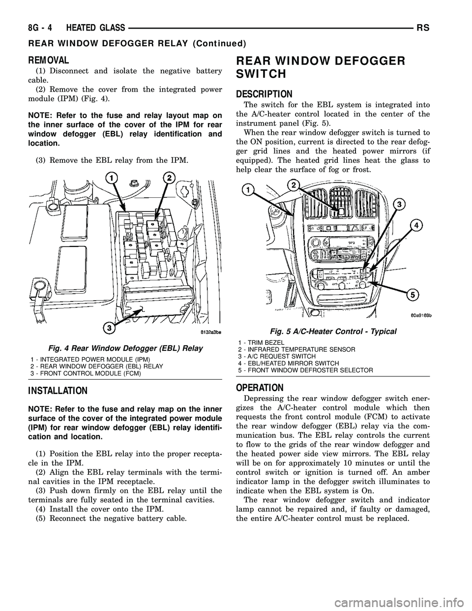
(1) Disconnect and isolate the negative battery
cable.
(2) Remove the cover from the integrated power
module (IPM) (Fig. 4).
NOTE: Refer to the fuse and relay layout map on
the inner surface of the cover of the IPM for rear
window defogger (EBL) relay identification and
location.
(3) Remove the EBL relay from the IPM.
INSTALLATION
NOTE: Refer to the fuse and relay map on the inner
surface of the cover of the integrated power module
(IPM) for rear window defogger (EBL) relay identifi-
cation and location.
(1) Position the EBL relay into the proper recepta-
cle in the IPM.
(2) Align the EBL relay terminals with the termi-
nal cavities in the IPM receptacle.
(3) Push down firmly on the EBL relay until the
terminals are fully seated in the terminal cavities.
(4) Install the cover onto the IPM.
(5) Reconnect the negative battery cable.
REAR WINDOW DEFOGGER
SWITCH
DESCRIPTION
The switch for the EBL system is integrated into
the A/C-heater control located in the center of the
instrument panel (Fig. 5).
When the rear window defogger switch is turned to
the ON position, current is directed to the rear defog-
ger grid lines and the heated power mirrors (if
equipped). The heated grid lines heat the glass to
help clear the surface of fog or frost.
OPERATION
Depressing the rear window defogger switch ener-
gizes the A/C-heater control module which then
requests the front control module (FCM) to activate
the rear window defogger (EBL) relay via the com-
munication bus. The EBL relay controls the current
to flow to the grids of the rear window defogger and
the heated power side view mirrors. The EBL relay
will be on for approximately 10 minutes or until the
control switch or ignition is turned off. An amber
indicator lamp in the defogger switch illuminates to
indicate when the EBL system is On.
The rear window defogger switch and indicator
lamp cannot be repaired and, if faulty or damaged,
the entire A/C-heater control must be replaced.
Fig. 4 Rear Window Defogger (EBL) Relay
1 - INTEGRATED POWER MODULE (IPM)
2 - REAR WINDOW DEFOGGER (EBL) RELAY
3 - FRONT CONTROL MODULE (FCM)
Fig. 5 A/C-Heater Control - Typical
1 - TRIM BEZEL
2 - INFRARED TEMPERATURE SENSOR
3 - A/C REQUEST SWITCH
4 - EBL/HEATED MIRROR SWITCH
5 - FRONT WINDOW DEFROSTER SELECTOR
8G - 4 HEATED GLASSRS
REAR WINDOW DEFOGGER RELAY (Continued)