torque CHRYSLER VOYAGER 2005 Service Manual
[x] Cancel search | Manufacturer: CHRYSLER, Model Year: 2005, Model line: VOYAGER, Model: CHRYSLER VOYAGER 2005Pages: 2339, PDF Size: 59.69 MB
Page 1410 of 2339
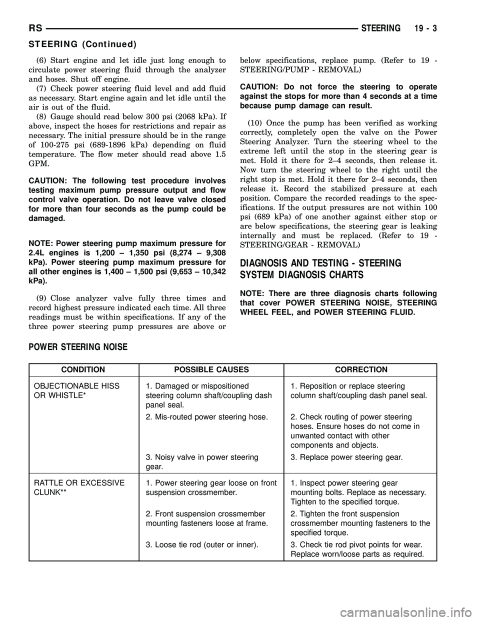
(6) Start engine and let idle just long enough to
circulate power steering fluid through the analyzer
and hoses. Shut off engine.
(7) Check power steering fluid level and add fluid
as necessary. Start engine again and let idle until the
air is out of the fluid.
(8) Gauge should read below 300 psi (2068 kPa). If
above, inspect the hoses for restrictions and repair as
necessary. The initial pressure should be in the range
of 100-275 psi (689-1896 kPa) depending on fluid
temperature. The flow meter should read above 1.5
GPM.
CAUTION: The following test procedure involves
testing maximum pump pressure output and flow
control valve operation. Do not leave valve closed
for more than four seconds as the pump could be
damaged.
NOTE: Power steering pump maximum pressure for
2.4L engines is 1,200 ± 1,350 psi (8,274 ± 9,308
kPa). Power steering pump maximum pressure for
all other engines is 1,400 ± 1,500 psi (9,653 ± 10,342
kPa).
(9) Close analyzer valve fully three times and
record highest pressure indicated each time. All three
readings must be within specifications. If any of the
three power steering pump pressures are above orbelow specifications, replace pump. (Refer to 19 -
STEERING/PUMP - REMOVAL)
CAUTION: Do not force the steering to operate
against the stops for more than 4 seconds at a time
because pump damage can result.
(10) Once the pump has been verified as working
correctly, completely open the valve on the Power
Steering Analyzer. Turn the steering wheel to the
extreme left until the stop in the steering gear is
met. Hold it there for 2±4 seconds, then release it.
Now turn the steering wheel to the right until the
right stop is met. Hold it there for 2±4 seconds, then
release it. Record the stabilized pressure at each
position. Compare the recorded readings to the spec-
ifications. If the output pressures are not within 100
psi (689 kPa) of one another against either stop or
are below specifications, the steering gear is leaking
internally and must be replaced. (Refer to 19 -
STEERING/GEAR - REMOVAL)
DIAGNOSIS AND TESTING - STEERING
SYSTEM DIAGNOSIS CHARTS
NOTE: There are three diagnosis charts following
that cover POWER STEERING NOISE, STEERING
WHEEL FEEL, and POWER STEERING FLUID.
POWER STEERING NOISE
CONDITION POSSIBLE CAUSES CORRECTION
OBJECTIONABLE HISS
OR WHISTLE*1. Damaged or mispositioned
steering column shaft/coupling dash
panel seal.1. Reposition or replace steering
column shaft/coupling dash panel seal.
2. Mis-routed power steering hose. 2. Check routing of power steering
hoses. Ensure hoses do not come in
unwanted contact with other
components and objects.
3. Noisy valve in power steering
gear.3. Replace power steering gear.
RATTLE OR EXCESSIVE
CLUNK**1. Power steering gear loose on front
suspension crossmember.1. Inspect power steering gear
mounting bolts. Replace as necessary.
Tighten to the specified torque.
2. Front suspension crossmember
mounting fasteners loose at frame.2. Tighten the front suspension
crossmember mounting fasteners to the
specified torque.
3. Loose tie rod (outer or inner). 3. Check tie rod pivot points for wear.
Replace worn/loose parts as required.
RSSTEERING19-3
STEERING (Continued)
Page 1411 of 2339

CONDITION POSSIBLE CAUSES CORRECTION
4. Loose lower control arm mounting
bolts at front suspension
crossmember.4. Tighten control arm mounting bolts to
the specified torques.
5. Lower control arm pivot bushing
worn.5. Replace lower control arm pivot
bushing.
6. Loose strut assembly mounting
fasteners at tower or knuckle.6. Tighten strut assembly fasteners to
the specified torque.
7. Power steering fluid hose touching
the body of the vehicle.7. Adjust hose to proper position by
loosening, repositioning, and tightening
attachments to specified torque. Do not
bend tubing.
8. Damaged front suspension
crossmember.8. Replace front suspension
crossmember.
9. Stabilizer bar link ball joints worn. 9. Replace stabilizer bar link.
10. Lug nuts loose. 10. Tighten lug nuts to specifications.
11. Excessive Wheel bearing
free-play.11. Verify correct halfshaft hub nut
torque. Replace hub and bearing if
torque is okay.
12. Internal power steering gear
noise.12. Replace power steering gear.
POPPING NOISE 1. Worn outer tie rod. 1. Check ball joint for free-play;
Replace outer tie rod.
2. Loose inner tie rod. 2. Replace power steering gear.
CHIRP OR SQUEAL
(POWER STEERING
PUMP)1. Loose power steering pump drive
belt.1. Check and adjust power steering
pump drive belt to specifications or
replace automatic tensioner where
applicable. Replace belt if worn or
glazed.
2. Malfuctioning belt auto-tensioner 2. Replace belt auto-tensioner.
WHINE, GROWL, MOAN
OR GROAN (POWER
STEERING PUMP)***1. Low fluid level. 1. Fill power steering fluid reservoir to
proper level and check for leaks (make
sure all air is bled from the system
fluid).
2. Power steering hose touching
vehicle body or frame.2. Adjust hose to proper position by
loosening, repositioning, and tightening
fitting to specified torque. Do not bend
tubing. Replace hose if damaged.
3. Extremely low ambient
temperature.3. Some noise can be expected, but will
go away as vehicle warms. Replace
pump if noise is excessive.
4. Extreme wear of power steering
pump internal components.4. Replace power steering pump and
flush system as necessary.
19 - 4 STEERINGRS
STEERING (Continued)
Page 1413 of 2339

STEERING WHEEL FEEL
CONDITION POSSIBLE CAUSES CORRECTION
STEERING WHEEL/
COLUMN CLICKING,
CLUNKING OR RATTLING.1. Loose steering coupling pinch
bolt.1. Replace pinch bolt and torque to
specifications.
2. Steering column bearings. 2. Replace steering column.
3. Excessive intermediate shaft
coupling free-play.3. Replace intermediate shaft.
STEERING WHEEL HAS
FORE AND AFT
LOOSENESS.1. Steering wheel retaining nut not
properly tightened and torqued.1. Tighten the steering wheel retaining nut
to its specified torque.
2. Steering column lower bearing
spring retainer slipped on steering
column shaft.2. Replace steering column.
3. Loose steering column to
instrument panel fasteners.3. Tighten fasteners to specified torque.
STEERING WHEEL, DASH
OR VEHICLE VIBRATES
DURING LOW SPEED OR
STANDSTILL STEERING
MANEUVERS.1. Air in the fluid of the power
steering system.1. Bleed air from system following the
power steering pump initial operation
service procedure.*
2. Tires not properly inflated. 2. Inflate tires to the specified pressure.
3. Excessive engine vibration. 3. Ensure that the engine is tuned properly.
4. Loose tie rod end jam nut. 4. Tighten the inner to outer tie rod jam nut
to the specified torque.
5.Overcharged air conditioning
system.5.Check air conditioning pump head
pressure and correct as necessary.
6. Grounded engine mount. 6. Repair as necessary.
7. Loose outer tie rod. 7. Replace outer tie rod.
STEERING CATCHES,
SURGES OR STICKS IN
CERTAIN POSITIONS OR
IS DIFFICULT TO TURN. ***1. Low power steering fluid level. 1. Fill power steering fluid reservoir to
specified level and check for leaks.
2. Tires not inflated to specified
pressure.2. Inflate tires to the specified pressure.
3. Lack of lubrication in front lower
control arm ball joints.3. Lubricate ball joints if ball joints are not a
lubricated-for-life type ball joint. If ball joint
is a lubricated-for-life ball joint, replace ball
joint.
4. Worn or binding lower control arm
ball joint.4. Replace lower control arm ball joint.
5. Lack of lubrication in steering gear
outer tie rod ends.5. Lubricate tie rod ends if they are not a
lubricated-for-life type. If tie rod end is a
lubricated-for-life type, replace tie rod end.
19 - 6 STEERINGRS
STEERING (Continued)
Page 1415 of 2339
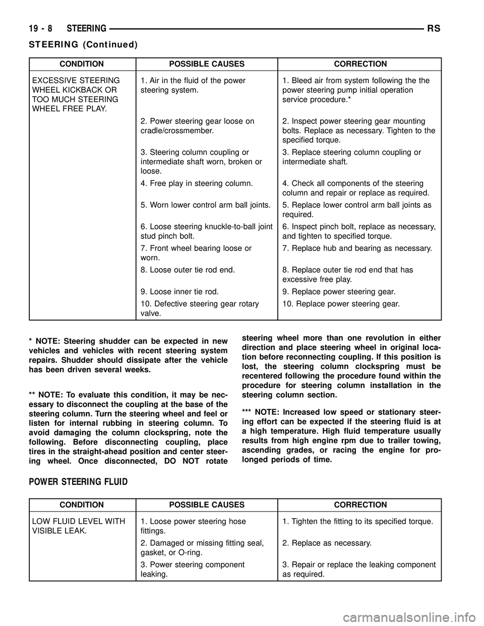
CONDITION POSSIBLE CAUSES CORRECTION
EXCESSIVE STEERING
WHEEL KICKBACK OR
TOO MUCH STEERING
WHEEL FREE PLAY.1. Air in the fluid of the power
steering system.1. Bleed air from system following the the
power steering pump initial operation
service procedure.*
2. Power steering gear loose on
cradle/crossmember.2. Inspect power steering gear mounting
bolts. Replace as necessary. Tighten to the
specified torque.
3. Steering column coupling or
intermediate shaft worn, broken or
loose.3. Replace steering column coupling or
intermediate shaft.
4. Free play in steering column. 4. Check all components of the steering
column and repair or replace as required.
5. Worn lower control arm ball joints. 5. Replace lower control arm ball joints as
required.
6. Loose steering knuckle-to-ball joint
stud pinch bolt.6. Inspect pinch bolt, replace as necessary,
and tighten to specified torque.
7. Front wheel bearing loose or
worn.7. Replace hub and bearing as necessary.
8. Loose outer tie rod end. 8. Replace outer tie rod end that has
excessive free play.
9. Loose inner tie rod. 9. Replace power steering gear.
10. Defective steering gear rotary
valve.10. Replace power steering gear.
* NOTE: Steering shudder can be expected in new
vehicles and vehicles with recent steering system
repairs. Shudder should dissipate after the vehicle
has been driven several weeks.
** NOTE: To evaluate this condition, it may be nec-
essary to disconnect the coupling at the base of the
steering column. Turn the steering wheel and feel or
listen for internal rubbing in steering column. To
avoid damaging the column clockspring, note the
following. Before disconnecting coupling, place
tires in the straight-ahead position and center steer-
ing wheel. Once disconnected, DO NOT rotatesteering wheel more than one revolution in either
direction and place steering wheel in original loca-
tion before reconnecting coupling. If this position is
lost, the steering column clockspring must be
recentered following the procedure found within the
procedure for steering column installation in the
steering column section.
*** NOTE: Increased low speed or stationary steer-
ing effort can be expected if the steering fluid is at
a high temperature. High fluid temperature usually
results from high engine rpm due to trailer towing,
ascending grades, or racing the engine for pro-
longed periods of time.
POWER STEERING FLUID
CONDITION POSSIBLE CAUSES CORRECTION
LOW FLUID LEVEL WITH
VISIBLE LEAK.1. Loose power steering hose
fittings.1. Tighten the fitting to its specified torque.
2. Damaged or missing fitting seal,
gasket, or O-ring.2. Replace as necessary.
3. Power steering component
leaking.3. Repair or replace the leaking component
as required.
19 - 8 STEERINGRS
STEERING (Continued)
Page 1416 of 2339

CONDITION POSSIBLE CAUSES CORRECTION
AERATED FLUID.* 1. Low fluid level. 1. Fill power steering fluid reservoir to
proper level.
2. Air leak at supply hose, power
steering fluid reservoir or pump.2. Inspect for proper sealing. Repair as
necessary.
3. Cracked power steering pump
housing.3. Replace the power steering pump.
RESERVOIR FLUID
OVERFLOW AND FLUID
THAT IS MILKY IN COLOR1. Water contamination of power
steering fluid.1. Drain the power steering fluid from the
system. Flush the system with fresh clean
power steering fluid, drain, then refill to the
proper level.
* NOTE: Extremely cold temperatures may cause
power steering fluid aeration. Aeration should sub-
side as fluid warms.
SPECIFICATIONS
POWER STEERING FASTENER TORQUE
DESCRIPTION TORQUE
Power Steering Pump:
Flow Control Valve
Pressure Fitting75 N´m (55 ft. lbs.)
Mounting Bolts 54 N´m (40 ft. lbs.)
Rear Bracket To Engine
Mounting Bolts54 N´m (40 ft. lbs.)
Steering Gear:
Mounting Bolt - Size-M14 183 N´m (135 ft. lbs.)
Mounting Bolts -
Size-M1295 N´m (70 ft. lbs.)
Tie Rod Steering Knuckle
Nut75 N´m (55 ft. lbs.)
Tie Rod Jam Nut 75 N´m (55 ft. lbs.)
Coupling Pinch Bolt 28 N´m (250 in. lbs.)
Power Steering Fluid
Hoses:
Hose Tube Nuts 31 N´m (275 in. lbs.)
Routing Bracket Bolts 23 N´m (200 in. lbs.)
SPECIAL TOOLS
POWER STEERING
Power Steering Analyzer 6815
Adapters, Power Steering Analyzer 6893
Hose, Power Steering Analyzer 6959
RSSTEERING19-9
STEERING (Continued)
Page 1417 of 2339
COLUMN
TABLE OF CONTENTS
page page
COLUMN
DESCRIPTION - STEERING COLUMN.......10
WARNING
WARNINGS AND CAUTIONS.............10
DIAGNOSIS AND TESTING - STEERING
COLUMN............................11
REMOVAL.............................11
INSTALLATION.........................16
SPECIFICATIONS
COLUMN FASTENER TORQUE...........17
IGNITION SWITCH
REMOVAL.............................17
INSTALLATION.........................19
KEY/LOCK CYLINDER
DESCRIPTION.........................20OPERATION...........................20
REMOVAL.............................20
INSTALLATION.........................20
SHROUD - LOWER
REMOVAL.............................21
INSTALLATION.........................21
SHROUD - UPPER
REMOVAL.............................22
INSTALLATION.........................22
STEERING WHEEL
REMOVAL.............................23
INSTALLATION.........................24
COLUMN
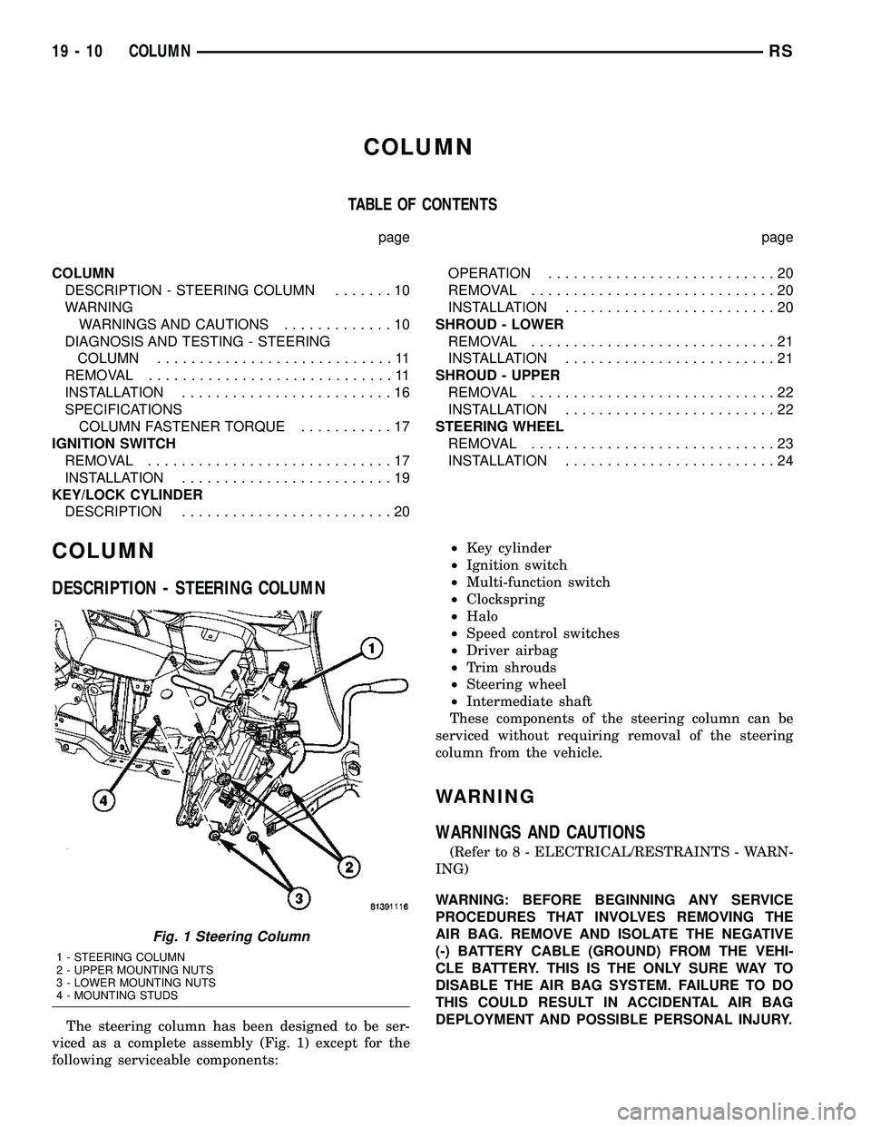
DESCRIPTION - STEERING COLUMN
The steering column has been designed to be ser-
viced as a complete assembly (Fig. 1) except for the
following serviceable components:²Key cylinder
²Ignition switch
²Multi-function switch
²Clockspring
²Halo
²Speed control switches
²Driver airbag
²Trim shrouds
²Steering wheel
²Intermediate shaft
These components of the steering column can be
serviced without requiring removal of the steering
column from the vehicle.
WARNING
WARNINGS AND CAUTIONS
(Refer to 8 - ELECTRICAL/RESTRAINTS - WARN-
ING)
WARNING: BEFORE BEGINNING ANY SERVICE
PROCEDURES THAT INVOLVES REMOVING THE
AIR BAG. REMOVE AND ISOLATE THE NEGATIVE
(-) BATTERY CABLE (GROUND) FROM THE VEHI-
CLE BATTERY. THIS IS THE ONLY SURE WAY TO
DISABLE THE AIR BAG SYSTEM. FAILURE TO DO
THIS COULD RESULT IN ACCIDENTAL AIR BAG
DEPLOYMENT AND POSSIBLE PERSONAL INJURY.
Fig. 1 Steering Column
1 - STEERING COLUMN
2 - UPPER MOUNTING NUTS
3 - LOWER MOUNTING NUTS
4 - MOUNTING STUDS
19 - 10 COLUMNRS
Page 1423 of 2339
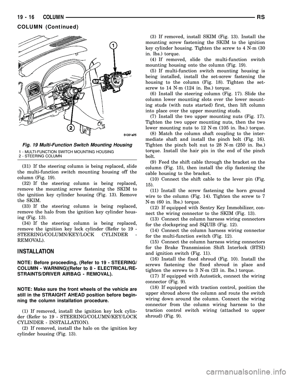
(31) If the steering column is being replaced, slide
the multi-function switch mounting housing off the
column (Fig. 19).
(32) If the steering column is being replaced,
remove the mounting screw fastening the SKIM to
the ignition key cylinder housing (Fig. 13). Remove
the SKIM.
(33) If the steering column is being replaced,
remove the halo from the ignition key cylinder hous-
ing (Fig. 13).
(34) If the steering column is being replaced,
remove the ignition key lock cylinder (Refer to 19 -
STEERING/COLUMN/KEY/LOCK CYLINDER -
REMOVAL).
INSTALLATION
NOTE: Before proceeding, (Refer to 19 - STEERING/
COLUMN - WARNING)(Refer to 8 - ELECTRICAL/RE-
STRAINTS/DRIVER AIRBAG - REMOVAL).
NOTE: Make sure the front wheels of the vehicle are
still in the STRAIGHT AHEAD position before begin-
ning the column installation procedure.
(1) If removed, install the ignition key lock cylin-
der (Refer to 19 - STEERING/COLUMN/KEY/LOCK
CYLINDER - INSTALLATION).
(2) If removed, install the halo on the ignition key
cylinder housing (Fig. 13).(3) If removed, install SKIM (Fig. 13). Install the
mounting screw fastening the SKIM to the ignition
key cylinder housing. Tighten the screw to 4 N´m (30
in. lbs.) torque.
(4) If removed, slide the multi-function switch
mounting housing onto the column (Fig. 19).
(5) If multi-function switch mounting housing is
being installed, install the set-screw fastening the
housing to the column (Fig. 18). Tighten the set-
screw to 14 N´m (124 in. lbs.) torque.
(6) Install the steering column (Fig. 17). Slide the
column lower mounting slots over the lower mount-
ing studs (with nuts started) first, then lift column
into place over the upper mounting studs.
(7) Install the two upper mounting nuts (Fig. 17).
Tighten the two upper mounting nuts, then the two
lower mounting nuts to 12 N´m (105 in. lbs.) torque.
(8) Match the column shaft coupling to the inter-
mediate shaft and install the pinch bolt (Fig. 16).
Tighten the pinch bolt nut to 28 N´m (250 in. lbs.)
torque. Install the hair pin in the end of the pinch
bolt.
(9) Feed the shift cable through the bracket on the
column (Fig. 15), then install the clip fastening the
cable housing to the bracket.
(10) Connect the shift cable to the lever pin (Fig.
15).
(11) Install the screw fastening the horn ground
wire to the column (Fig. 14). Tighten the screw to 7
N´m (60 in. lbs.) torque.
(12) If equipped with Sentry Key Immobilizer, con-
nect the wiring connector to the SKIM (Fig. 13).
(13) Connect the column harness wiring connectors
for the clockspring and SQUIB (Fig. 12).
(14) Connect the column harness wiring connector
for the multi-function switch (Fig. 12).
(15) Connect the column harness wiring connectors
for the Brake Transmission Shift Interlock (BTSI)
and ignition switch (Fig. 11).
(16) Install the fixed shroud (Fig. 10). Install the
screws fastening the fixed shroud in place and
tighten the screws to 3 N´m (23 in. lbs.) torque.
(17) If equipped with Autostick, connect the wiring
connector (Fig. 9).
(18) If equipped with traction control, position the
upper shroud above the column and route the switch
wiring down around the column. Connect the wiring
connector from the column wiring harness to the
traction control switch wiring (attached to upper
shroud) (Fig. 9).
Fig. 19 Multi-Function Switch Mounting Housing
1 - MULTI-FUNCTION SWITCH MOUNTING HOUSING
2 - STEERING COLUMN
19 - 16 COLUMNRS
COLUMN (Continued)
Page 1424 of 2339
(19) Position the lower shroud on the column (Fig.
8). Install the lower shroud mounting screw. Tighten
the screw to 2 N´m (17 in. lbs.) torque.
(20) If equipped with adjustable pedals, Connect
the wiring connector for the switch (Fig. 7) to the col-
umn wiring harness.
(21) Position the upper shroud on top of the lower
shroud and snap it into place. Install the upper
shroud mounting screws (Fig. 6). Tighten the screws
to 2 N´m (17 in. lbs.) torque.
(22) Inspect shroud mating surfaces for excessive
gaps and correct as necessary.
(23) Install the cluster trim bezel (Refer to 23 -
BODY/INSTRUMENT PANEL/CLUSTER BEZEL -
INSTALLATION).
(24) Install the knee blocker/steering column cover
plate. (Refer to 23 - BODY/INSTRUMENT PANEL/
KNEE BLOCKER - INSTALLATION)
(25) Install the parking brake handle link.
(26) Install the knee blocker/steering column open-
ing cover. (Refer to 23 - BODY/INSTRUMENT PAN-
EL/STEERING COLUMN OPENING COVER -
INSTALLATION)
(27) Align the splines and install the steering
wheel on the steering column shaft(Refer to 19 -
STEERING/COLUMN/STEERING WHEEL -
INSTALLATION).
(28) Install the damper over the steering column
shaft (Fig. 4).
(29) Install the steering wheel retaining bolt (Fig.
4). Tighten the bolt to 61 N´m (45 ft. lbs.) torque.
(30) If the steering wheel is equipped with remote
audio controls, connect the wiring connector to the
clockspring (Fig. 4).
(31) Connect the two squib connectors to the
driver airbag (Fig. 3). The connectors are color coded
to avoid connector mix-up.
(32) Connect the speed control and horn connector
to the clockspring (Fig. 3).
(33) Install the airbag to the steering wheel.
Install the driver airbag mounting screws (Fig. 2).
Tighten screws to 10 N´m (90 in. lbs.) torque.
(34) Connect the battery negative (ground) cable to
battery post following special Diagnosis And Testing
procedure. (Refer to 8 - ELECTRICAL/RESTRAINTS
- DIAGNOSIS AND TESTING)
(35) Check operation of all steering column
mounted components.
(36) Road test vehicle to ensure proper operation
of steering.SPECIFICATIONS
COLUMN FASTENER TORQUE
DESCRIPTION N´mFt.
Lbs.In.
Lbs.
Driver Airbag Mounting Screws 10 Ð 90
Multi-Function Switch Mounting
Housing Set-Screw14 Ð 124
Shroud Attaching Screws - Fixed 3 Ð 23
Shroud Attaching Screws -
Lower/Upper2Ð17
SKIM Attaching Screw 4 Ð 30
Steering Column Coupling Pinch
Bolt28 Ð 250
Steering Column Mounting Nuts 12 Ð 105
Steering Wheel Retaining Bolt 61 45 Ð
IGNITION SWITCH
REMOVAL
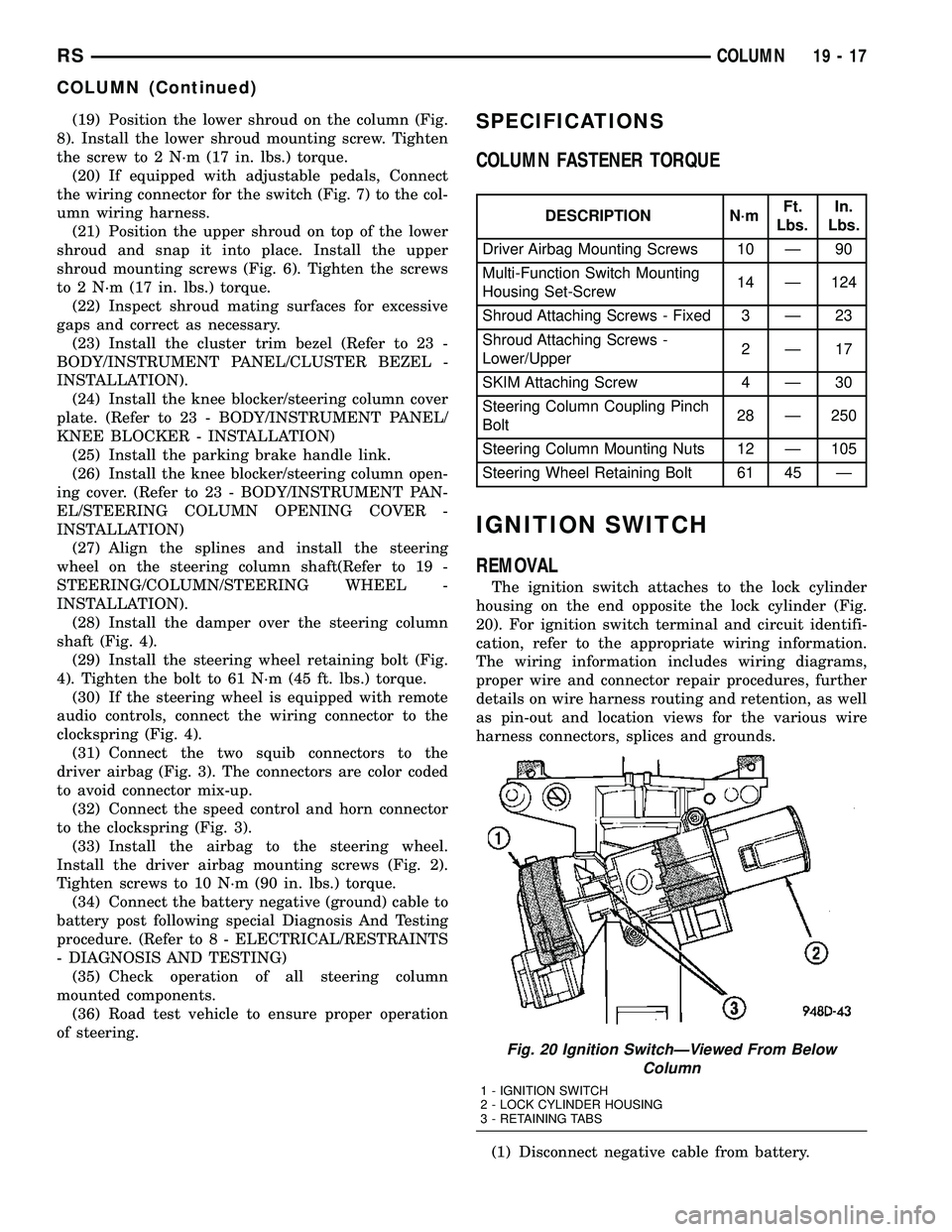
The ignition switch attaches to the lock cylinder
housing on the end opposite the lock cylinder (Fig.
20). For ignition switch terminal and circuit identifi-
cation, refer to the appropriate wiring information.
The wiring information includes wiring diagrams,
proper wire and connector repair procedures, further
details on wire harness routing and retention, as well
as pin-out and location views for the various wire
harness connectors, splices and grounds.
(1) Disconnect negative cable from battery.
Fig. 20 Ignition SwitchÐViewed From Below
Column
1 - IGNITION SWITCH
2 - LOCK CYLINDER HOUSING
3 - RETAINING TABS
RSCOLUMN19-17
COLUMN (Continued)
Page 1428 of 2339
SHROUD - LOWER
REMOVAL
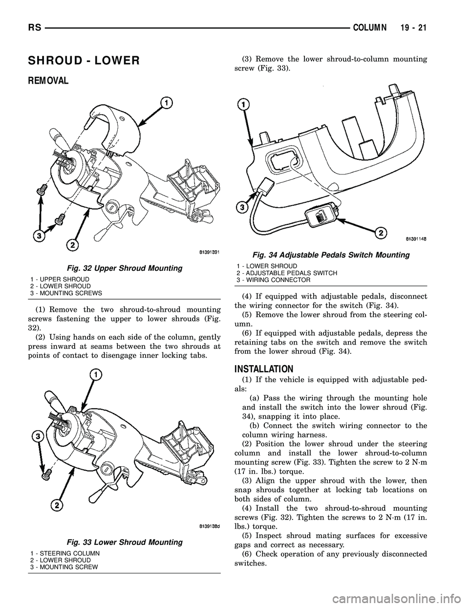
(1) Remove the two shroud-to-shroud mounting
screws fastening the upper to lower shrouds (Fig.
32).
(2) Using hands on each side of the column, gently
press inward at seams between the two shrouds at
points of contact to disengage inner locking tabs.(3) Remove the lower shroud-to-column mounting
screw (Fig. 33).
(4) If equipped with adjustable pedals, disconnect
the wiring connector for the switch (Fig. 34).
(5) Remove the lower shroud from the steering col-
umn.
(6) If equipped with adjustable pedals, depress the
retaining tabs on the switch and remove the switch
from the lower shroud (Fig. 34).
INSTALLATION
(1) If the vehicle is equipped with adjustable ped-
als:
(a) Pass the wiring through the mounting hole
and install the switch into the lower shroud (Fig.
34), snapping it into place.
(b) Connect the switch wiring connector to the
column wiring harness.
(2) Position the lower shroud under the steering
column and install the lower shroud-to-column
mounting screw (Fig. 33). Tighten the screw to 2 N´m
(17 in. lbs.) torque.
(3) Align the upper shroud with the lower, then
snap shrouds together at locking tab locations on
both sides of column.
(4) Install the two shroud-to-shroud mounting
screws (Fig. 32). Tighten the screws to 2 N´m (17 in.
lbs.) torque.
(5) Inspect shroud mating surfaces for excessive
gaps and correct as necessary.
(6) Check operation of any previously disconnected
switches.
Fig. 32 Upper Shroud Mounting
1 - UPPER SHROUD
2 - LOWER SHROUD
3 - MOUNTING SCREWS
Fig. 33 Lower Shroud Mounting
1 - STEERING COLUMN
2 - LOWER SHROUD
3 - MOUNTING SCREW
Fig. 34 Adjustable Pedals Switch Mounting
1 - LOWER SHROUD
2 - ADJUSTABLE PEDALS SWITCH
3 - WIRING CONNECTOR
RSCOLUMN19-21
Page 1430 of 2339
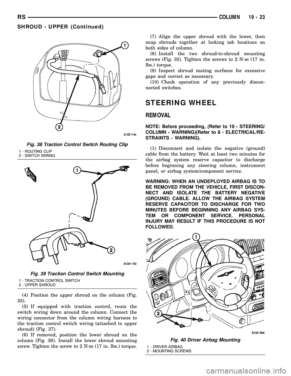
(4) Position the upper shroud on the column (Fig.
35).
(5) If equipped with traction control, route the
switch wiring down around the column. Connect the
wiring connector from the column wiring harness to
the traction control switch wiring (attached to upper
shroud) (Fig. 37).
(6) If removed, position the lower shroud on the
column (Fig. 36). Install the lower shroud mounting
screw. Tighten the screw to 2 N´m (17 in. lbs.) torque.(7) Align the upper shroud with the lower, then
snap shrouds together at locking tab locations on
both sides of column.
(8) Install the two shroud-to-shroud mounting
screws (Fig. 35). Tighten the screws to 2 N´m (17 in.
lbs.) torque.
(9) Inspect shroud mating surfaces for excessive
gaps and correct as necessary.
(10) Check operation of any previously discon-
nected switches.
STEERING WHEEL
REMOVAL
NOTE: Before proceeding, (Refer to 19 - STEERING/
COLUMN - WARNING)(Refer to 8 - ELECTRICAL/RE-
STRAINTS - WARNING).
(1) Disconnect and isolate the negative (ground)
cable from the battery. Wait at least two minutes for
the airbag system reserve capacitor to discharge
before beginning any steering column, instrument
panel, or airbag system/component service.
WARNING: WHEN AN UNDEPLOYED AIRBAG IS TO
BE REMOVED FROM THE VEHICLE, FIRST DISCON-
NECT AND ISOLATE THE BATTERY NEGATIVE
(GROUND) CABLE. ALLOW THE AIRBAG SYSTEM
RESERVE CAPACITOR TO DISCHARGE FOR TWO
MINUTES BEFORE BEGINNING ANY AIRBAG SYS-
TEM OR COMPONENT SERVICE. PERSONAL
INJURY MAY RESULT IF THIS PROCEDURE IS NOT
FOLLOWED.
Fig. 38 Traction Control Switch Routing Clip
1 - ROUTING CLIP
2 - SWITCH WIRING
Fig. 39 Traction Control Switch Mounting
1 - TRACTION CONTROL SWITCH
2 - UPPER SHROUD
Fig. 40 Driver Airbag Mounting
1 - DRIVER AIRBAG
2 - MOUNTING SCREWS
RSCOLUMN19-23
SHROUD - UPPER (Continued)