3 row CHRYSLER VOYAGER 2005 Owner's Manual
[x] Cancel search | Manufacturer: CHRYSLER, Model Year: 2005, Model line: VOYAGER, Model: CHRYSLER VOYAGER 2005Pages: 2339, PDF Size: 59.69 MB
Page 523 of 2339

(3) Remove the hinge retaining bolts under the
cushion cover side panel (Fig. 42).
(4) Gently lift hinge upwards to free buckle from
between the cushion frame and the hinge itself (Fig.
43).(5) Remove buckle half from seat.
INSTALLATION
QUAD BUCKET
(1) Place buckle into position.
(2) Install bolt attaching seat belt buckle to seat
track. Torque bolt to 39 N´m (29 ft. lbs.).
(3) Install recliner bracket onto the seat.
(4) Install bolts attaching recliner bracket to seat
cushion.
(5) Install side cover from seat.
(6) Install screws attaching inboard side cover to
seat cushion.
(7) Install seat into position.
QUAD BUCKET - FOLD IN FLOOR
(1) Gently lift hinge upwards and place buckle in
between the cushion frame and the hinge itself (Fig.
43).
(2) Install the hinge retaining bolts under the
cushion cover side panel (Fig. 42).
(3) Install the hinge cover retaining screw and
hinge cover.
SEAT BELT BUCKLE - FIRST
ROW - BENCH
REMOVAL
(1) Remove seat from vehicle.
(2) Remove bolt attaching inboard seat belt buckle
to seat frame (Fig. 44).
(3) Remove belt from seat.
Fig. 42 1ST ROW INBOARD BUCKLE RETAINING
BOLTS - FOLD IN FLOOR
1 - SEAT BELT BUCKLE
2 - SEAT BACK INBOARD HINGE
3 - SEAT RISER
4 - INBOARD HINGE RETAINING BOLTS
5 - SEAT CUSHION COVER SIDE PANEL
Fig. 43 1ST ROW INBOARD BUCKLE - FOLD IN
FLOOR
1 - SEAT BACK HINGE
2 - SEAT BELT BUCKLE
3 - SEAT CUSHION FRAME
Fig. 44 SEAT BELT BUCKLE - FIRST ROW - BENCH
1 - ANCHOR BOLT
2 - TWO (2) PASS REAR SEAT BELT BUCKLE
3 - RISER
4 - REAR FRAME
8O - 36 RESTRAINTSRS
SEAT BELT BUCKLE - FIRST ROW INBOARD - QUAD BUCKET (Continued)
Page 524 of 2339

INSTALLATION
(1) Place seat belt into position to the seat.
(2) Install bolt attaching inboard seat belt buckle
to seat frame. Tighten all seat belt anchor bolts to 39
N´m (29 ft. lbs.) torque.
(3) Install seat into position.
SEAT BELT BUCKLE - SECOND
ROW INBOARD - 50/50 BENCH
REMOVAL
SECOND ROW 50/50 BENCH
(1) Open rear liftgate.
(2) Pull handle #1 and fold seat back forward.
(3) Pull handle #2, and lift seat bottom up.
(4) Pull #3 strap and remove seat from latching
area.
(5) While looking at the bottom of the seat, locate
retaining bolt on the left side of the seat riser.
Remove retaining bolt from seat riser (Fig. 45).
(6) Pull belt through seat cushion.
SECOND ROW - FOLD IN FLOOR
(1) Fold in floor the seat not having the buckle
replaced.(2) Remove the hinge cover retaining screw (Fig.
46).
(3) Pull hinge cover out just far enough to gain
access to buckle retaining nut (Fig. 47). Remove nut
and slide buckle out from under cushion cover side
panel.
Fig. 45 SEAT BELT BUCKLE - SECOND ROW
INBOARD - 50/50 BENCH
1 - SEAT BELT BUCKLE
2 - BUCKLE RETAINING BOLT
3 - 50/50 SPLIT BENCH RISER
4 - BOTTOM OF SEAT CUSHION
Fig. 46 FIRST ROW BUCKLE - INBOARD - COVER
RETAINING SCREW
1 - SEAT BELT BUCKLE
2 - HINGE COVER
3 - HINGE COVER RETAINING SCREW
4 - CUSHION COVER SIDE PANEL
Fig. 47 FIRST ROW BUCKLE - INBOARD -
RETAINING NUT
1 - SEAT BELT BUCKLE
2 - HINGE COVER
3 - SEAT BELT BUCKLE RETAINING NUT
4 - CUSHION COVER SIDE PANEL
RSRESTRAINTS8O-37
SEAT BELT BUCKLE - FIRST ROW - BENCH (Continued)
Page 525 of 2339

INSTALLATION
(1) Push belt through seat cushion.
(2) While looking at the bottom of the seat, locate
retaining bolt hole on the left side of the seat riser.
Install retaining bolt into seat riser (Fig. 45). Torque
anchor bolt to 39 N´m (29 ft. lbs.).
(3) Place seat into track and on front anchors.
(4) Pull #3 strap and install seat onto latching
area.
(5) Pull seat assembly down firmly and snap into
track.
(6) Pull handle #1 and fold seat back rearward.
(7) Close rear liftgate.
SEAT BELT HEIGHT
ADJUSTER-BORC-PILLAR
REMOVAL
(1) Remove turning loop retaining bolt.
(2) Remove B or C-pillar trim cover.
(3) Remove two screws attaching shoulder belt
height adjuster to pillar.
(4) Remove height adjuster from vehicle.
INSTALLATION
(1) Place height adjuster into position.
(2) Install screws attaching shoulder belt height
adjuster to pillar.
(3) Install B or C-pillar trim cover.
(4) Install turning loop to height adjuster. Torque
anchor bolt to 39 N´m (29 ft. lbs.).
SEAT BELT HEIGHT
ADJUSTER KNOB
REMOVAL
(1) Disengage clips attaching clam shell cover to
seat belt turning loop and open cover.
(2) Using a trim tool (special tool #C-4755), gently
pry knob from seat belt height adjuster.
INSTALLATION
(1) Place seat belt height adjuster knob in position
on height adjuster.
(2) Firmly push knob on until retainers engage.
(3) Reinstall turning loop clam shell cover.
(4) Verify seat belt operation. Make sure it moves
through loop without binding.
SEAT BELT & RETRACTOR -
OUTBOARD - FRONT
REMOVAL
(1) Open door.
(2) Move seat all the way forward.
(3) Open hood.
(4) Disconnect and isolate the battery negative
cable.
(5)
WARNING: Wait two minutes for the airbag system
reserve capacitor to discharge before beginning
any airbag system or component service. Failure to
do so may result in accidental airbag deployment,
personal injury or death.
(6) Remove shoulder harness height adjuster knob
by pulling it straight away from adjuster (Fig. 48).
(7) Remove cover from seat belt turning loop (Fig.
48).
(8) Remove bolt attaching turning loop to shoulder
belt height adjuster (Fig. 48).
(9) Remove upper B-pillar trim cover (Fig. 48).
NOTE: If equipped with the Occupant Classification
System (OCS), there is a Belt Tension Sensor
located on the lower seat belt anchor on the pas-
senger front seat belt.
Fig. 48 SEAT BELT - OUTBOARD FRONT
1 - B-PILLAR TRIM LOWER
2 - BELT
3 - B-PILLAR TRIM UPPER
4 - HEIGHT ADJUSTER
5 - KNOB
6 - B-PILLAR TRIM LOWER
7 - FLOOR ANCHOR
8 - FLOOR ANCHOR
9 - 30É OUTBOARD
10 - RETRACTOR
8O - 38 RESTRAINTSRS
SEAT BELT BUCKLE - SECOND ROW INBOARD - 50/50 BENCH (Continued)
Page 526 of 2339

(10) Remove the lower seat belt anchor bolt (Fig.
49).
(11) Disconnect the electrical connector if equipped
with OCS (Fig. 49).
(12) Remove front door sill plate (Fig. 48).
(13) Remove sliding door sill plate (Fig. 48).
(14) Remove lower B-pillar trim cover (Fig. 48).
(15) Disconnect the seat belt retractor electrical
connector (Fig. 48).
(16) Remove seat belt retractor attaching bolt (Fig.
48).
(17) Remove the seat belt and retractor from vehi-
cle.
INSTALLATION
WARNING: Inspect the condition of the shoulder
belt and lap belt. Replace any belt that is cut,
frayed, torn, or damaged in any way. Also, replace
the shoulder belt if the retractor is either damaged
or inoperative.
(1) Place seat belt and retractor into position (Fig.
48).
(2) Install bolt attaching seat belt retractor to
B-pillar (Fig. 48). Torque bolt to 39 N´m (29 ft. lbs.).
(3) Connect the seat belt retractor electrical con-
nector (Fig. 48).
(4) Install the lower B-pillar trim cover (Fig. 48).
(5) Install the sliding door sill plate (Fig. 48).
(6) Install the front door sill plate (Fig. 48).(7) Install the lower seat belt anchor bolt (Fig. 49).
Torque bolt to 39 N´m (29 ft. lbs.).
NOTE: If equipped with the Occupant Classification
System (OCS), there is a Belt Tension Sensor
located on the lower seat belt anchor on the pas-
senger front seat belt.
(8) Connect the belt tension sensor connector (if
equipped with OCS) (Fig. 49).
(9) Install the upper B-pillar trim cover (Fig. 48).
(10) Install the bolt attaching turning loop to
shoulder belt height adjuster (Fig. 48). Torque bolt to
39 N´m (29 ft. lbs.).
(11) Install the cover to the seat belt turning loop
(Fig. 48).
(12) Install the shoulder harness height adjuster
knob by pushing it straight onto the adjuster (Fig.
48).
(13) Move seat back to approximate customer posi-
tion.
WARNING: If equipped with the OCS, do not con-
nect the battery negative cable (Refer to 8 - ELEC-
TRICAL/RESTRAINTS - DIAGNOSIS AND TESTING -
AIRBAG SYSTEM). Personal injury or death may
result if the system test is not performed first.
WARNING: If equipped with the OCS, following suc-
cessful completion of the Airbag System test proce-
dure, the Occupant Classification System
Verification Test must be done using a scan tool
and the appropriate diagnostic information.
(14) Verify vehicle and system operation.
(15) Close hood.
SEAT BELT & RETRACTOR -
FIRST ROW - OUTBOARD
REMOVAL
(1) Remove first and second row seats.
(2) Remove first row seat belt lower anchor bolt.
(3) Remove first row seat belt upper turning loop
anchor bolt.
(4) Remove liftgate sill plate.
(5) Remove upper liftgate trim.
(6) Remove second seat lower anchor bolt.
(7) Remove second seat upper turning loop anchor
bolt.
(8) Remove D-pillar trim cover.
(9) Disconnect speaker connector. The left side has
the speaker mounted in the D-pillar trim cover and
the right side will have the speaker mounted in the
rear of the quarter trim panel, but the connector is
Fig. 49 BELT TENSION SENSOR/LOWER SEAT
BELT ANCHOR
1 - A-PILLAR
2 - SEAT BELT ANCHOR/BELT TENSION SENSOR
3 - BELT TENSION SENSOR CONNECTOR
RSRESTRAINTS8O-39
SEAT BELT & RETRACTOR - OUTBOARD - FRONT (Continued)
Page 527 of 2339

accessible from the rear after the D-pillar trim is
removed.
(10) Remove quarter trim bolster.
(11) Remove quarter trim panel screws.
(12) Remove quarter trim panel.
(13) Remove first row seat belt and retractor
retaining bolt.
(14) Remove first row seat belt and retractor from
vehicle.
INSTALLATION
(1) Install first row seat belt and retractor. Torque
bolt to 39 N´m (29 ft. lbs.).
(2) Install quarter trim panel.
(3) Install quarter trim panel screws.
(4) Install quarter trim bolster.
(5) Connect speaker connector. The left side has
the speaker mounted in the D-pillar trim cover and
the right side will have the speaker mounted in the
rear of the quarter trim panel, but the connector is
accessible from the rear after the D-pillar trim is
removed.
(6) Install D-pillar trim cover.
(7) Install second seat belt lower anchor bolt.
Torque bolt to 39 N´m (29 ft. lbs.).
(8) Install second seat belt upper turning loop
anchor bolt. Torque bolt to 39 N´m (29 ft. lbs.).
(9) Install upper liftgate trim.
(10) Install liftgate sill plate.
(11) Install first row seat belt upper turning loop
anchor bolt. Torque bolt to 39 N´m (29 ft. lbs.).
(12) Install first row seat belt lower anchor bolt.
Torque bolt to 39 N´m (29 ft. lbs.).
(13) Install first and second row seats.
SEAT BELT BUCKLE - SECOND
ROW - THREE PASSENGER
BENCH
REMOVAL
(1) Remove bolt attaching seat belt buckle to seat
rear frame rail (Fig. 50).
(2) Remove seat belt buckle from seat.
INSTALLATION
(1) Place seat belt buckle in position on seat.
(2) Install bolt to attach seat belt buckle to seat
rear frame rail. Tighten all seat belt bolts to 39 N´m
(29 ft. lbs.) torque.
SEAT BELT & RETRACTOR -
SECOND ROW - RIGHT
OUTBOARD
REMOVAL
(1) Remove first and second row seats.
(2) Remove first row seat belt lower anchor bolt.
(3) Remove first row seat belt upper anchor bolt.
(4) Remove liftgate sill plate.
(5) Remove upper liftgate trim.
(6) Remove second seat belt lower anchor bolt.
(7) Remove second seat belt upper anchor bolt.
(8) Remove D-pillar trim cover.
(9) Disconnect speaker connector. The left side has
the speaker mounted in the D-pillar trim cover and
the right side will have the speaker mounted in the
rear of the quarter trim panel, but the connector is
accessible from the rear after the D-pillar trim is
removed.
(10) Remove quarter trim bolster.
(11) Remove quarter trim panel screws.
(12) Remove quarter trim panel.
(13) Remove retractor retaining bolt.
(14) Remove second row seat belt and retractor.
INSTALLATION
(1) Install second row seat belt and retractor.
Torque bolt to 39 N´m (29 ft. lbs.).
(2) Install quarter trim panel.
(3) Install quarter trim panel screws.
(4) Install quarter trim bolster.
(5) Connect speaker connector. The left side has
the speaker mounted in the D-pillar trim cover and
Fig. 50 SEAT BELT BUCKLE - SECOND ROW -
THREE PASSENGER BENCH
1 - ANCHOR BOLT
2 - SEAT BELTS
3 - ANCHOR
4 - RISER
8O - 40 RESTRAINTSRS
SEAT BELT & RETRACTOR - FIRST ROW - OUTBOARD (Continued)
Page 528 of 2339

the right side will have the speaker mounted in the
rear of the quarter trim panel, but the connector is
accessible from the rear after the D-pillar trim is
removed.
(6) Install D-pillar trim cover.
(7) Install second seat belt lower anchor bolt.
Torque bolt to 39 N´m (29 ft. lbs.).
(8) Install second seat belt upper turning loop
anchor bolt. Torque bolt to 39 N´m (29 ft. lbs.).
(9) Install upper liftgate trim.
(10) Install liftgate sill plate.
(11) Install first row seat belt upper turning loop
anchor bolt. Torque bolt to 39 N´m (29 ft. lbs.).
(12) Install first row seat belt lower anchor bolt.
Torque bolt to 39 N´m (29 ft. lbs.).
(13) Install first and second row seats.
SEAT BELT & RETRACTOR -
SECOND ROW - RIGHT
OUTBOARD WITH REAR HVAC
-LWB
REMOVAL
(1) Remove first and second row seats.
(2) Remove first row seat belt lower anchor bolt.
(3) Remove first row seat belt upper anchor bolt.
(4) Remove liftgate sill plate.
(5) Remove upper liftgate trim.
(6) Remove second seat belt lower anchor bolt.
(7) Remove second seat belt upper anchor bolt.
(8) Remove D-pillar trim cover.
(9) Disconnect speaker connector. The left side has
the speaker mounted in the D-pillar trim cover and
the right side will have the speaker mounted in the
rear of the quarter trim panel, but the connector is
accessible from the rear after the D-pillar trim is
removed.
(10) Remove quarter trim bolster.
(11) Remove quarter trim panel screws.
(12) Remove quarter trim panel.
(13) Loosen HVAC unit enough to gain access to
seat belt retractor fasteners.
(a) Remove bracket around HVAC unit (Fig. 51).
(b) Remove air duct (Fig. 52).
(c) Remove fasteners attaching HVAC unit to
inner quarter panel (Fig. 53).
(d) Gently pry out on rear HVAC unit to gain
access to the seat belt and retractor.
(14) Remove bolts attaching seat belt guide loop to
inner quarter panel.
(15) Pull outward on HVAC unit and remove bolt
attaching retractor to inner quarter panel.
(16) Remove second row seat belt and retractor
from vehicle.
INSTALLATION
(1) Position second row seat belt and retractor to
vehicle.
(2) Pull outward on HVAC unit and install bolt
attaching retractor to inner quarter panel. Torque
bolt to 39 N´m (29 ft. lbs.).
(3) Install bolts attaching seat belt guide loop to
inner quarter panel.
(4) Install fasteners attaching HVAC unit to inner
quarter panel.
(5) Install air duct.
(6) Install trim panel retaining bracket around
HVAC unit.
(7) Install quarter trim panel.
(8) Install quarter trim panel screws.
(9) Install quarter trim bolster.
(10) Connect speaker connector. The left side has
the speaker mounted in the D-pillar trim cover and
Fig. 51 TRIM PANEL MOUNTING BRACKET
1 - TRIM PANEL MOUNTING BRACKET
Fig. 52 LOWER HEATER DUCT
1 - LOWER HEAT DUCT MOUNTING
RSRESTRAINTS8O-41
SEAT BELT & RETRACTOR - SECOND ROW - RIGHT OUTBOARD (Continued)
Page 529 of 2339

the right side will have the speaker mounted in the
rear of the quarter trim panel, but the connector is
accessible from the rear after the D-pillar trim is
removed.
(11) Install D-pillar trim cover.
(12) Install second seat belt lower anchor bolt.
Torque bolt to 39 N´m (29 ft. lbs.).
(13) Install second seat belt upper turning loop
anchor bolt. Torque bolt to 39 N´m (29 ft. lbs.).
(14) Install upper liftgate trim.
(15) Install liftgate sill plate.
(16) Install first row seat belt upper turning loop
anchor bolt. Torque bolt to 39 N´m (29 ft. lbs.).
(17) Install first row seat belt lower anchor bolt.
Torque bolt to 39 N´m (29 ft. lbs.).
(18) Install first and second row seats.
SEAT BELT & RETRACTOR -
SECOND ROW - LEFT
OUTBOARD
REMOVAL
(1) Remove first and second row seats.
(2) Remove first row seat belt lower anchor bolt.
(3) Remove first row seat belt upper anchor bolt.
(4) Remove liftgate sill plate.
(5) Remove upper liftgate trim.
(6) Remove second seat belt lower anchor bolt.
(7) Remove second seat belt upper anchor bolt.
(8) Remove D-pillar trim cover.
(9) Disconnect speaker connector. The left side has
the speaker mounted in the D-pillar trim cover and
the right side will have the speaker mounted in the
rear of the quarter trim panel, but the connector is
accessible from the rear after the D-pillar trim is
removed.
(10) Remove quarter trim bolster.
(11) Remove quarter trim panel screws.
(12) Remove quarter trim panel.
(13) Remove retractor retaining bolt.
(14) Remove second row seat belt and retractor
from vehicle.
INSTALLATION
(1) Install second row seat belt and retractor.
Torque bolt to 39 N´m (29 ft. lbs.).
(2) Install quarter trim panel.
(3) Install quarter trim panel screws.
(4) Install quarter trim bolster.
(5) Connect speaker connector. The left side has
the speaker mounted in the D-pillar trim cover and
the right side will have the speaker mounted in the
rear of the quarter trim panel, but the connector is
accessible from the rear after the D-pillar trim is
removed.
(6) Install D-pillar trim cover.
(7) Install second seat belt lower anchor bolt.
Torque bolt to 39 N´m (29 ft. lbs.).
(8) Install second seat belt upper turning loop
anchor bolt. Torque bolt to 39 N´m (29 ft. lbs.).
(9) Install upper liftgate trim.
(10) Install liftgate sill plate.
(11) Install first row seat belt upper turning loop
anchor bolt. Torque bolt to 39 N´m (29 ft. lbs.).
(12) Install first row seat belt lower anchor bolt.
Torque bolt to 39 N´m (29 ft. lbs.).
(13) Install first and second row seats.
Fig. 53 REAR HVAC MOUNTING
1 - REAR HVAC MODULE MOUNTING
2 - REAR EVAPORATOR LOWER HOUSING
3 - REAR EVAPORATOR UPPER HOUSING
8O - 42 RESTRAINTSRS
SEAT BELT & RETRACTOR - SECOND ROW - RIGHT OUTBOARD WITH REAR HVAC - LWB (Continued)
Page 570 of 2339
TERMINOLOGY
This is a list of terms and definitions used in the
wiring diagrams.
LHD.................Left Hand Drive Vehicles
RHD ...............Right Hand Drive Vehicles
ATX . . Automatic Transmissions-Front Wheel Drive
MTX . . . Manual Transmissions-Front Wheel Drive
AT....Automatic Transmissions-Rear Wheel Drive
MT .....Manual Transmissions-Rear Wheel Drive
SOHC...........Single Over Head Cam Engine
DOHC..........Double Over Head Cam Engine
Export . . Vehicles Built For Sale In Markets Other
Than North America
Except Export.... Vehicles Built For Sale In North
America
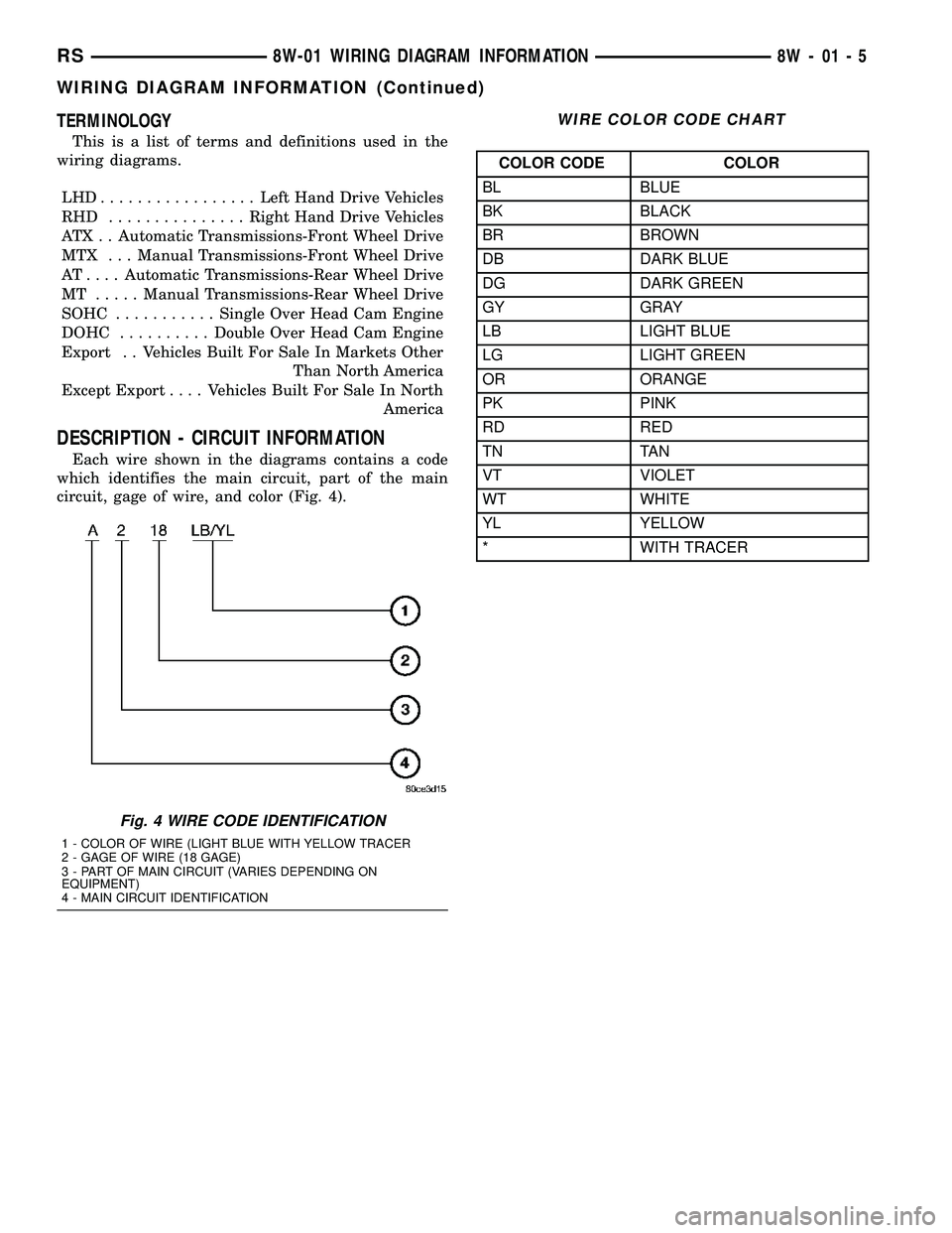
DESCRIPTION - CIRCUIT INFORMATION
Each wire shown in the diagrams contains a code
which identifies the main circuit, part of the main
circuit, gage of wire, and color (Fig. 4).
WIRE COLOR CODE CHART
COLOR CODE COLOR
BL BLUE
BK BLACK
BR BROWN
DB DARK BLUE
DG DARK GREEN
GY GRAY
LB LIGHT BLUE
LG LIGHT GREEN
OR ORANGE
PK PINK
RD RED
TN TAN
VT VIOLET
WT WHITE
YL YELLOW
* WITH TRACER
Fig. 4 WIRE CODE IDENTIFICATION
1 - COLOR OF WIRE (LIGHT BLUE WITH YELLOW TRACER
2 - GAGE OF WIRE (18 GAGE)
3 - PART OF MAIN CIRCUIT (VARIES DEPENDING ON
EQUIPMENT)
4 - MAIN CIRCUIT IDENTIFICATION
RS8W-01 WIRING DIAGRAM INFORMATION8W-01-5
WIRING DIAGRAM INFORMATION (Continued)
Page 1027 of 2339

DOSING PUMP (DIESEL) - BLACK 2 WAY
CAV CIRCUIT FUNCTION
1 18RD DOSING PUMP CONTROL
2 Z149 18BK/DB GROUND
DRIVER AIRBAG SQUIB 1 - BROWN/YELLOW 2 WAY
CAV CIRCUIT FUNCTION
1 R43 20OR/LB DRIVER SQUIB 1 LINE 2
2 R45 20TN/LB DRIVER SQUIB 1 LINE 1
DRIVER AIRBAG SQUIB 2 - BLACK/YELLOW 2 WAY
CAV CIRCUIT FUNCTION
1 R61 20LG/VT DRIVER SQUIB 2 LINE 2
2 R63 20OR/LB DRIVER SQUIB 2 LINE 1
DRIVER BLEND DOOR ACTUATOR - GRAY 2 WAY
CAV CIRCUIT FUNCTION
1 C61 20DB/LG (ATC) DRIVER BLEND DOOR DRIVER (A)
1 C61 20LB/WT (LHD) DRIVER BLEND DOOR DRIVER (A)
1 C34 20DB/LB (RHD) COMMON DOOR DRIVER (B)
2 C161 20LB/WT (ATC) DRIVER BLEND DOOR DRIVER (B)
2 C34 20DB/LB (LHD) COMMON DOOR DRIVER (B)
2 C61 20LB/WT (RHD) DRIVER BLEND DOOR DRIVER (A)
8W - 80 - 58 8W-80 CONNECTOR PIN-OUTSRS
Page 1222 of 2339
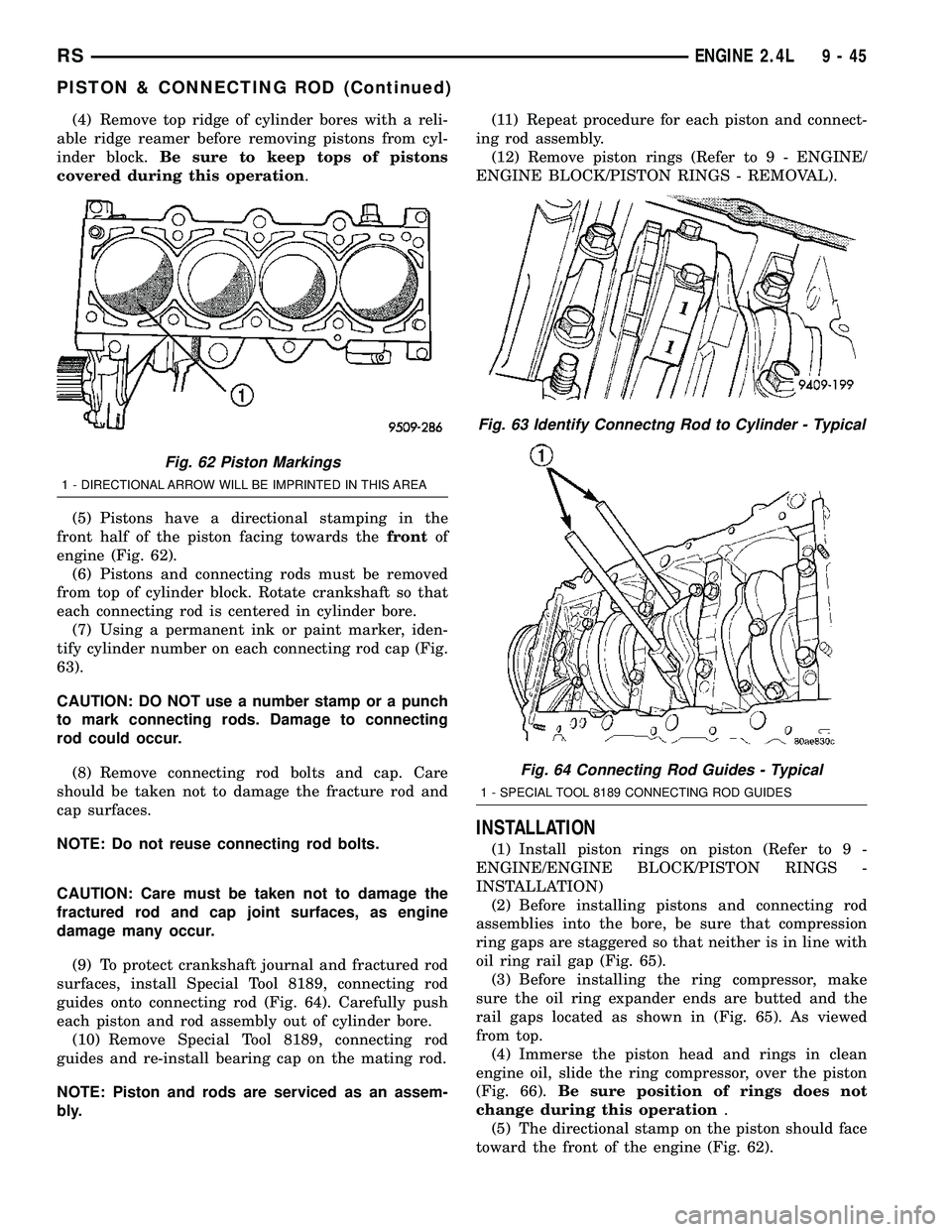
(4) Remove top ridge of cylinder bores with a reli-
able ridge reamer before removing pistons from cyl-
inder block.Be sure to keep tops of pistons
covered during this operation.
(5) Pistons have a directional stamping in the
front half of the piston facing towards thefrontof
engine (Fig. 62).
(6) Pistons and connecting rods must be removed
from top of cylinder block. Rotate crankshaft so that
each connecting rod is centered in cylinder bore.
(7) Using a permanent ink or paint marker, iden-
tify cylinder number on each connecting rod cap (Fig.
63).
CAUTION: DO NOT use a number stamp or a punch
to mark connecting rods. Damage to connecting
rod could occur.
(8) Remove connecting rod bolts and cap. Care
should be taken not to damage the fracture rod and
cap surfaces.
NOTE: Do not reuse connecting rod bolts.
CAUTION: Care must be taken not to damage the
fractured rod and cap joint surfaces, as engine
damage many occur.
(9) To protect crankshaft journal and fractured rod
surfaces, install Special Tool 8189, connecting rod
guides onto connecting rod (Fig. 64). Carefully push
each piston and rod assembly out of cylinder bore.
(10) Remove Special Tool 8189, connecting rod
guides and re-install bearing cap on the mating rod.
NOTE: Piston and rods are serviced as an assem-
bly.(11) Repeat procedure for each piston and connect-
ing rod assembly.
(12) Remove piston rings (Refer to 9 - ENGINE/
ENGINE BLOCK/PISTON RINGS - REMOVAL).
INSTALLATION
(1) Install piston rings on piston (Refer to 9 -
ENGINE/ENGINE BLOCK/PISTON RINGS -
INSTALLATION)
(2) Before installing pistons and connecting rod
assemblies into the bore, be sure that compression
ring gaps are staggered so that neither is in line with
oil ring rail gap (Fig. 65).
(3) Before installing the ring compressor, make
sure the oil ring expander ends are butted and the
rail gaps located as shown in (Fig. 65). As viewed
from top.
(4) Immerse the piston head and rings in clean
engine oil, slide the ring compressor, over the piston
(Fig. 66).Be sure position of rings does not
change during this operation.
(5) The directional stamp on the piston should face
toward the front of the engine (Fig. 62).
Fig. 62 Piston Markings
1 - DIRECTIONAL ARROW WILL BE IMPRINTED IN THIS AREA
Fig. 63 Identify Connectng Rod to Cylinder - Typical
Fig. 64 Connecting Rod Guides - Typical
1 - SPECIAL TOOL 8189 CONNECTING ROD GUIDES
RSENGINE 2.4L9-45
PISTON & CONNECTING ROD (Continued)