3 row CHRYSLER VOYAGER 2005 Workshop Manual
[x] Cancel search | Manufacturer: CHRYSLER, Model Year: 2005, Model line: VOYAGER, Model: CHRYSLER VOYAGER 2005Pages: 2339, PDF Size: 59.69 MB
Page 1543 of 2339
FLUID
STANDARD PROCEDURE
FLUID LEVEL AND CONDITION CHECK
NOTE: Only transmission fluid of the type labeled
Mopar ATF+4 (Automatic Transmission Fluid)
should be used in this transaxle.
FLUID LEVEL CHECK
The transmission sump has a fluid level indicator
(dipstick) to check oil similar to most automatic
transmissions. It is located on the left side of the
engine. Be sure to wipe all dirt from dipstick handle
before removing.
The torque converter fills in both the P Park and N
Neutral positions. Place the selector lever in P Park
to be sure that the fluid level check is accurate.The
engine should be running at idle speed for at
least one minute, with the vehicle on level
ground.At normal operating temperature 82É C
(180É F), the fluid level is correct if it is in the HOT
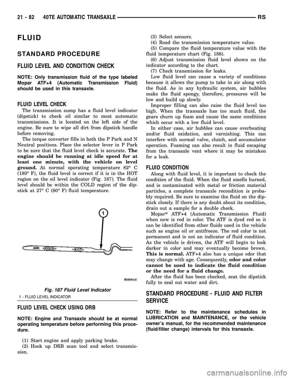
region on the oil level indicator (Fig. 187). The fluid
level should be within the COLD region of the dip-
stick at 27É C (80É F) fluid temperature.
FLUID LEVEL CHECK USING DRB
NOTE: Engine and Transaxle should be at normal
operating temperature before performing this proce-
dure.
(1) Start engine and apply parking brake.
(2) Hook up DRB scan tool and select transmis-
sion.(3) Select sensors.
(4) Read the transmission temperature value.
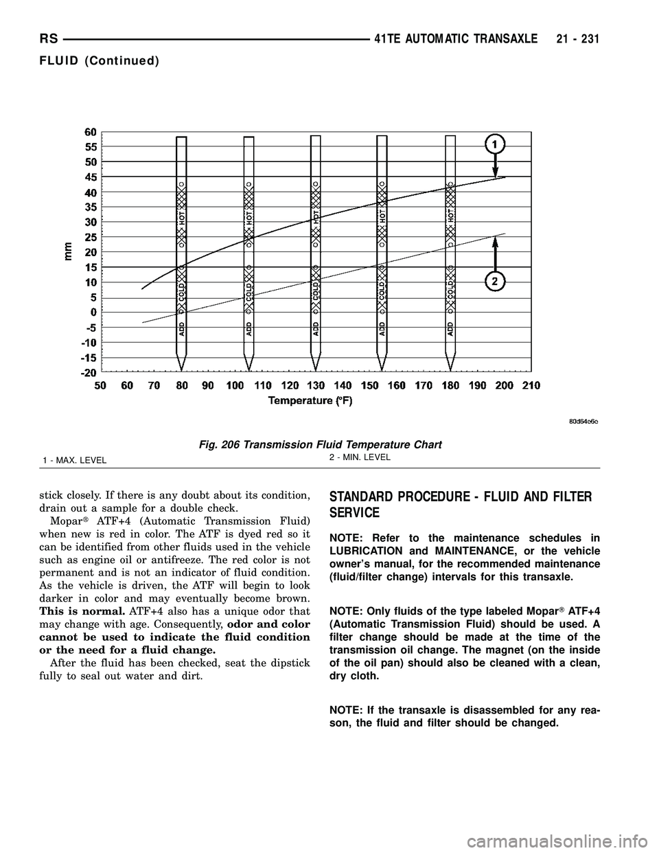
(5) Compare the fluid temperature value with the
fluid temperature chart (Fig. 188).
(6) Adjust transmission fluid level shown on the
indicator according to the chart.
(7) Check transmission for leaks.
Low fluid level can cause a variety of conditions
because it allows the pump to take in air along with
the fluid. As in any hydraulic system, air bubbles
make the fluid spongy, therefore, pressures will be
low and build up slowly.
Improper filling can also raise the fluid level too
high. When the transaxle has too much fluid, the
gears churn up foam and cause the same conditions
which occur with a low fluid level.
In either case, air bubbles can cause overheating
and/or fluid oxidation, and varnishing. This can
interfere with normal valve, clutch, and accumulator
operation. Foaming can also result in fluid escaping
from the transaxle vent where it may be mistaken
for a leak.
FLUID CONDITION
Along with fluid level, it is important to check the
condition of the fluid. When the fluid smells burned,
and is contaminated with metal or friction material
particles, a complete transaxle recondition is proba-
bly required. Be sure to examine the fluid on the dip-
stick closely. If there is any doubt about its condition,
drain out a sample for a double check.
MopartATF+4 (Automatic Transmission Fluid)
when new is red in color. The ATF is dyed red so it
can be identified from other fluids used in the vehicle
such as engine oil or antifreeze. The red color is not
permanent and is not an indicator of fluid condition.
As the vehicle is driven, the ATF will begin to look
darker in color and may eventually become brown.
This is normal.ATF+4 also has a unique odor that
may change with age. Consequently,odor and color
cannot be used to indicate the fluid condition
or the need for a fluid change.
After the fluid has been checked, seat the dipstick
fully to seal out water and dirt.
STANDARD PROCEDURE - FLUID AND FILTER
SERVICE
NOTE: Refer to the maintenance schedules in
LUBRICATION and MAINTENANCE, or the vehicle
owner's manual, for the recommended maintenance
(fluid/filter change) intervals for this transaxle.
Fig. 187 Fluid Level Indicator
1 - FLUID LEVEL INDICATOR
21 - 82 40TE AUTOMATIC TRANSAXLERS
Page 1692 of 2339
stick closely. If there is any doubt about its condition,
drain out a sample for a double check.
MopartATF+4 (Automatic Transmission Fluid)
when new is red in color. The ATF is dyed red so it
can be identified from other fluids used in the vehicle
such as engine oil or antifreeze. The red color is not
permanent and is not an indicator of fluid condition.
As the vehicle is driven, the ATF will begin to look
darker in color and may eventually become brown.
This is normal.ATF+4 also has a unique odor that
may change with age. Consequently,odor and color
cannot be used to indicate the fluid condition
or the need for a fluid change.
After the fluid has been checked, seat the dipstick
fully to seal out water and dirt.STANDARD PROCEDURE - FLUID AND FILTER
SERVICE
NOTE: Refer to the maintenance schedules in
LUBRICATION and MAINTENANCE, or the vehicle
owner's manual, for the recommended maintenance
(fluid/filter change) intervals for this transaxle.
NOTE: Only fluids of the type labeled MoparTATF+4
(Automatic Transmission Fluid) should be used. A
filter change should be made at the time of the
transmission oil change. The magnet (on the inside
of the oil pan) should also be cleaned with a clean,
dry cloth.
NOTE: If the transaxle is disassembled for any rea-
son, the fluid and filter should be changed.
Fig. 206 Transmission Fluid Temperature Chart
1 - MAX. LEVEL2 - MIN. LEVEL
RS41TE AUTOMATIC TRANSAXLE21 - 231
FLUID (Continued)
Page 1761 of 2339

(5)Match Mounting.If the wheel runout is
within specifications, tire and wheel assembly runout
can be improved by re-indexing (match mounting)
the tire to the wheel as described below.
(a) Remount the tire on the rim 180 degrees
from its original location (Fig. 6). Ensure the tire
bead is properly seated.
(b) Re-measure the total runout. Mark the tire
at the high spot and record the measurement.
If runout is still excessive, perform the following:
²If the new high spot is within 102 mm (4.0 inch)
of the first high spot on the tire, replace the tire.
²If the new high spot is within 102 mm (4.0 inch)
of the first high spot on the wheel, the wheel may be
out of specification. Refer to Wheel Runout above.
²If the new high spot is NOT within 102 mm (4.0
inch) of either high spot, draw an arrow on the tread
from new high spot toward the original (Fig. 7).
Break down the tire and remount it 90 degrees on
rim in that direction, then re-measure runout. This
will normally reduce the runout to an acceptable
amount.
(6) Once back together, road test the vehicle for at
least 5 miles, following the format described in Road
Test. If vibration persists, and all components tested
are within specification, the tires may have an exces-
sive radial force condition. Radial force variation can
only be checked as indicated below. If this equipment
is not available, consult with the tire manufacturer.
Fig. 5 Checking Lateral Runout Of Wheel
1 - MOUNTING CONE
2 - SPINDLE SHAFT
3 - WING NUT
4 - PLASTIC CUP
5 - DIAL INDICATOR
6 - WHEEL
7 - DIAL INDICATOR
Fig. 6 Remount Tire 180 Degrees
1 - VALVE STEM
2 - REFERENCE MARK
Fig. 7 Remount Tire 90 Degrees In Direction of
Arrow
1 - 2ND HIGH SPOT ON TIRE
2 - 1ST HIGH SPOT ON TIRE
22 - 4 TIRES/WHEELSRS
TIRES/WHEELS (Continued)
Page 1764 of 2339

If difficult to balance, break down the wheel and
tire assembly and check for loose debris inside tire.
Prior to disassembly, mark (index) the tire at the
valve stem. Use this mark in order to remount the
tire in its original orientation with respect to the
wheel.
STANDARD PROCEDURE - TIRE AND WHEEL
MATCH MOUNTING
Wheels and tires are match mounted at the factory.
This means that the high spot of the tire is matched
to the low spot on the wheel rim. This technique is
used to reduce runout in the wheel and tire assem-
bly. The high spot on the tire is marked with a paint
mark or a bright colored adhesive label on the out-
board sidewall. The low spot on the wheel is identi-
fied with a label on the outside of the rim and a dot
or line in the drop well area of the rim (inside where
the tire mounts). If the outside label has been
removed, the tire will have to be removed to locate
the dot or line on the inside of the rim. The tire can
then be match mounted to the tire.
Information on match mounting the tire to the
wheel can be found in Tire and Wheel Runout/Match
Mounting, items (2) through (5), within Diagnosis
And Testing - Tire And Wheel Vibration. (Refer to 22
- TIRES/WHEELS - DIAGNOSIS AND TESTING)
STANDARD PROCEDURE - TIRE AND WHEEL
ROTATION
NON-DIRECTIONAL TREAD PATTERN TIRES
Tires on the front and rear axles operate at differ-
ent loads and perform different functions. For these
reasons, they wear at unequal rates, and tend to
develop irregular wear patterns. These effects can bereduced by timely rotation of tires. The benefits of
rotation are especially worthwhile. Rotation will
increase tread life, help to maintain mud, snow, and
wet traction levels, and contribute to a smooth, quiet
ride.
The suggested rotation method is the forward-cross
tire rotation method (Fig. 11). This method takes
advantage of current tire industry practice which
allows rotation of radial-ply tires. Other rotation
methods may be used, but may not have all the ben-
efits of the recommended method.
NOTE: Only the 4 tire rotation method may be used
if the vehicle is equipped with a low mileage or tem-
porary spare tire.
DIRECTIONAL TREAD PATTERN TIRES
Some vehicles are fitted with special high-perfor-
mance tires having a directional tread pattern. These
tires are designed to improve traction on wet pave-
ment. To obtain the full benefits of this design, the
tires must be installed so that they rotate in the cor-
rect direction. This is indicated by arrows on the tire
sidewalls.
When wheels and tires are being installed, extra
care is needed to ensure that this direction of rota-
tion is maintained.
Refer to Owner's Manual for rotation schedule.
Fig. 10 Aluminum Wheel Weight
1 - TIRE
2 - WHEEL
3 - WHEEL WEIGHT
Fig. 11 Forward-Cross Tire Rotation Method
RSTIRES/WHEELS22-7
TIRES/WHEELS (Continued)
Page 1829 of 2339

COWL GRILLE
REMOVAL
(1) Remove wiper arms. (Refer to 8 - ELECTRI-
CAL/WIPERS/WASHERS/WIPER ARMS -
REMOVAL)
(2) Remove four (4) screws securing cowl cover to
wiper module (Fig. 6).
(3) Disengage quarter turn fasteners at outboard
ends of cowl grill from body.
(4) Release hood latch and open hood.
CAUTION: To prevent hood scratching of cowl grille
before removal, cover outboard exterior ends of
cowl grille with masking tape or equivalent method.
NOTE: Do not over bend cowl grille during removal.
Bend cowl grille just enough to clear top of wiper
pivot shaft and bottom rear corner of hood.
(5) Remove cowl grill by raising above driver side
wiper pivot shaft and swinging away towards engine
compartment. The cowl grille will need to be bent onoutboard end to clear simultaneously top of wiper
pivot shaft and bottom corner of hood.
(6) Close hood. Do not latch. Remove outboard
screws. (Fig. 7).
(7) Disconnect washer hose in line connector.
(8) Disconnect washer hose and grommet from
hole in wiper module and pull out.
(9) Remove cowl grille by raising over opposite
wiper pivot shaft and removing away from vehicle.
(10) Remove cowl cover from vehicle.
INSTALLATION
(1) Reverse removal procedure.
(2) When installing cowl cover over wiper module,
make sure fore aft locator on the underside of cowl
grill seat into the locator grooves on top of wiper
module.
(3) Start all cowl grille mounting screws by hand
before torquing to specifications.
(4) Assure washer hose is properly routed and not
pinched.
(5) Center cowl grille to body and windshield.
(6) Assure ªarrowº indicator head of quarter turn
fasteners is pointing toward windshield.
Fig. 5 BODY SIDE MOLDINGS WITH APPLIQUE - TYPICAL
1 - FRONT ROCKER PANEL APPLIQUE
2 - FRONT DOOR MOLDING
3 - SLIDING DOOR MOLDING4 - REAR ROCKER PANEL APPLIQUE
5 - LIFTGATE MOLDING
6 - POP-RIVET
23 - 50 EXTERIORRS
BODY SIDE MOLDINGS (Continued)
Page 1838 of 2339
INSTALLATION
NOTE: The crossbar assemblies are designed to be
installed in only one way. Check top and bottom
surfaces of the crossbar for the word FRONT and
directional arrows. The directional arrows must
point toward the front of the vehicle.
(1) Place crossbar in position on vehicle.
(2) Work from side to side sliding the crossbar
assembly back a little at a time to ensure it remains
perpendicular to the side rails.
(3) Position first crossbar assembly crossbar at the
second most rearward locator holes. Press the top of
the stanchion lever to lock it into position.
(4) Position the second crossbar assembly in the
second hole from the front. Lock into place.
(5) Place luggage rack riser into position.
(6) Install two fasteners into riser. Tighten fasten-
ers to 4 mm (35 in. lbs.) torque.
REAR QUARTER PANEL/
FENDER AIR EXHAUSTER
DESCRIPTION
Air exhausters, designed to conform to the body
structure, allow air entering at the front of the vehi-
cle to flow out the back. By reducing air pressure
within the vehicle, the exhausters also reduce blower
noise at any given air flow level compared to operat-
ing without them and help reduce door closing effort.
They are located in the lower rear comers of the
body.
REMOVAL
SHORT WHEELBASE
(1) Remove the rear fascia from the body. (Refer to
13 - FRAMES & BUMPERS/BUMPERS/REAR FAS-
CIA - REMOVAL).
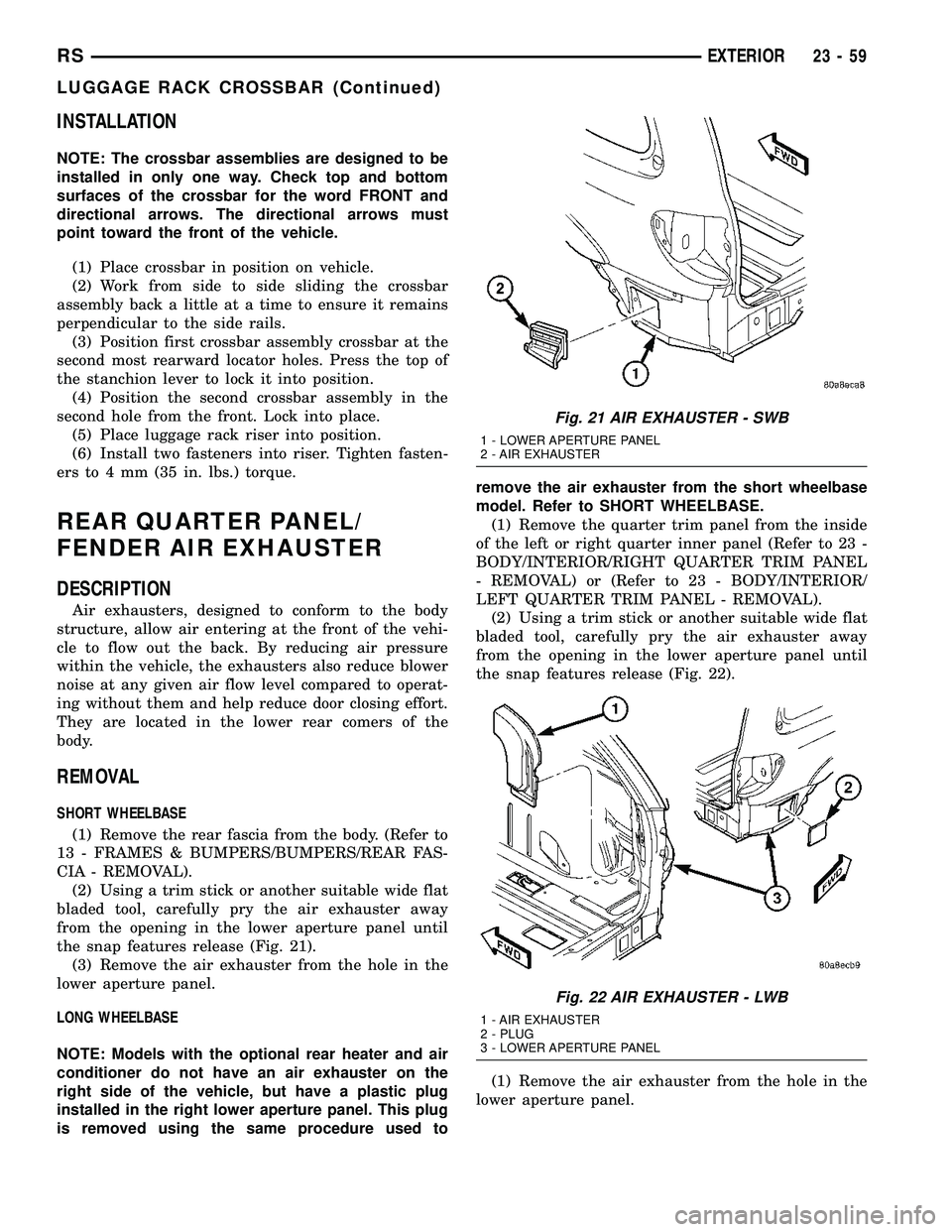
(2) Using a trim stick or another suitable wide flat
bladed tool, carefully pry the air exhauster away
from the opening in the lower aperture panel until
the snap features release (Fig. 21).
(3) Remove the air exhauster from the hole in the
lower aperture panel.
LONG WHEELBASE
NOTE: Models with the optional rear heater and air
conditioner do not have an air exhauster on the
right side of the vehicle, but have a plastic plug
installed in the right lower aperture panel. This plug
is removed using the same procedure used toremove the air exhauster from the short wheelbase
model. Refer to SHORT WHEELBASE.
(1) Remove the quarter trim panel from the inside
of the left or right quarter inner panel (Refer to 23 -
BODY/INTERIOR/RIGHT QUARTER TRIM PANEL
- REMOVAL) or (Refer to 23 - BODY/INTERIOR/
LEFT QUARTER TRIM PANEL - REMOVAL).
(2) Using a trim stick or another suitable wide flat
bladed tool, carefully pry the air exhauster away
from the opening in the lower aperture panel until
the snap features release (Fig. 22).
(1) Remove the air exhauster from the hole in the
lower aperture panel.
Fig. 21 AIR EXHAUSTER - SWB
1 - LOWER APERTURE PANEL
2 - AIR EXHAUSTER
Fig. 22 AIR EXHAUSTER - LWB
1 - AIR EXHAUSTER
2 - PLUG
3 - LOWER APERTURE PANEL
RSEXTERIOR23-59
LUGGAGE RACK CROSSBAR (Continued)
Page 1857 of 2339

INTERIOR
TABLE OF CONTENTS
page page
A-PILLAR LOWER EXTENSION TRIM
REMOVAL.............................79
INSTALLATION.........................79
A-PILLAR TRIM
REMOVAL.............................79
INSTALLATION.........................79
ASSIST HANDLE
REMOVAL.............................79
INSTALLATION.........................79
B-PILLAR LOWER TRIM
REMOVAL.............................79
INSTALLATION.........................80
B-PILLAR UPPER TRIM
REMOVAL.............................80
INSTALLATION.........................80
CARPETS AND FLOOR MATS
REMOVAL.............................81
INSTALLATION.........................81
CARPETS - FOLD-IN-FLOOR
REMOVAL.............................82
INSTALLATION.........................83
CARPET TRIM RING AND COVER - FOLD-IN-
FLOOR
REMOVAL.............................84
INSTALLATION.........................84
COWL TRIM
REMOVAL.............................88
INSTALLATION.........................88
C-PILLAR TRIM
REMOVAL.............................88
INSTALLATION.........................88
DOOR SILL TRIM PLATE
REMOVAL.............................89
INSTALLATION.........................89
FLOOR CONSOLE BASE TRAY
REMOVAL.............................89
INSTALLATION.........................89
FLOOR CONSOLE - FOLD-IN-FLOOR
REMOVAL.............................89
INSTALLATION.........................89
FLOOR CONSOLE KEY LOCK TUMBLER -
FOLD-IN-FLOOR
REMOVAL.............................90
INSTALLATION.........................90
FLOOR CONSOLE LID LATCH - FOLD-IN-
FLOOR
REMOVAL.............................90
INSTALLATION.........................90HEADLINER
REMOVAL.............................91
INSTALLATION.........................92
LEFT D-PILLAR TRIM PANEL
REMOVAL.............................94
INSTALLATION.........................94
LEFT QUARTER TRIM PANEL
REMOVAL.............................94
INSTALLATION.........................94
LIFTGATE SILL PLATE
REMOVAL.............................94
INSTALLATION.........................95
QUARTER TRIM BOLSTER
REMOVAL.............................95
INSTALLATION.........................95
REAR FLOOR TUB CARPETS INSERT -
FOLD-IN-FLOOR
REMOVAL.............................95
INSTALLATION.........................96
REAR HEADER TRIM
REMOVAL.............................96
INSTALLATION.........................96
REAR HVAC LOUVER
REMOVAL.............................96
INSTALLATION.........................97
RIGHT QUARTER TRIM PANEL
REMOVAL.............................97
INSTALLATION.........................97
REAR VIEW MIRROR
REMOVAL.............................97
INSTALLATION.........................97
RIGHT D-PILLAR TRIM PANEL
REMOVAL.............................97
INSTALLATION.........................98
SECOND ROW FLOOR TUB CARPET INSERT -
FOLD-IN-FLOOR
REMOVAL.............................98
INSTALLATION.........................98
SLIDING DOOR SILL PLATE
REMOVAL.............................98
INSTALLATION.........................99
SUN VISOR
REMOVAL.............................99
INSTALLATION.........................99
SUN VISOR SUPPORT
REMOVAL.............................99
INSTALLATION.........................99
23 - 78 INTERIORRS
Page 1861 of 2339
CARPETS - FOLD-IN-FLOOR
REMOVAL
(1) Remove floor mats.
(2) Remove front seats. (Refer to 23 - BODY/
SEATS/SEAT - REMOVAL)
(3) Remove instrument panel lower console. (Refer
to 23 - BODY/INSTRUMENT PANEL/STORAGE
BIN - REMOVAL).
(4) Remove the floor console base tray and discon-
nect wire connector from the base tray.(Refer to 23 -
BODY/INTERIOR/FLOOR CONSOLE BASE TRAY -
REMOVAL)
(5) Remove heel blocker (plastic block below accel-
erator pedal).
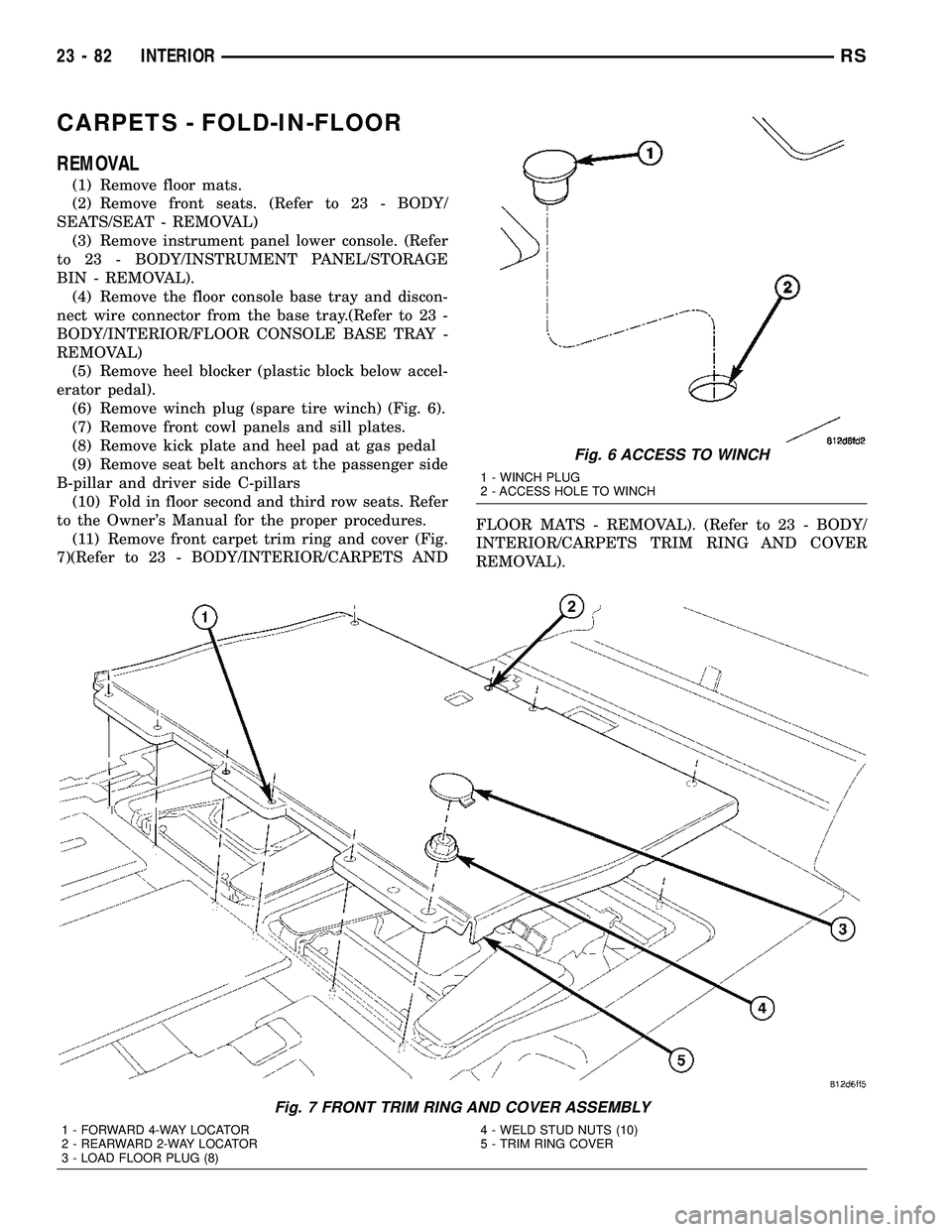
(6) Remove winch plug (spare tire winch) (Fig. 6).
(7) Remove front cowl panels and sill plates.
(8) Remove kick plate and heel pad at gas pedal
(9) Remove seat belt anchors at the passenger side
B-pillar and driver side C-pillars
(10) Fold in floor second and third row seats. Refer
to the Owner's Manual for the proper procedures.
(11) Remove front carpet trim ring and cover (Fig.
7)(Refer to 23 - BODY/INTERIOR/CARPETS ANDFLOOR MATS - REMOVAL). (Refer to 23 - BODY/
INTERIOR/CARPETS TRIM RING AND COVER
REMOVAL).
Fig. 6 ACCESS TO WINCH
1 - WINCH PLUG
2 - ACCESS HOLE TO WINCH
Fig. 7 FRONT TRIM RING AND COVER ASSEMBLY
1 - FORWARD 4-WAY LOCATOR
2 - REARWARD 2-WAY LOCATOR
3 - LOAD FLOOR PLUG (8)4 - WELD STUD NUTS (10)
5 - TRIM RING COVER
23 - 82 INTERIORRS
Page 1862 of 2339

(12) Remove sliding door sill plates. (Refer to 23 -
BODY/INTERIOR/SLIDING DOOR SILL PLATE -
REMOVAL)
(13) Remove lower B-pillar trim covers.
(14) Remove push pin fasteners attaching carpet to
floor in front seat area.
(15) Roll carpet from under instrument panel to
center of sliding door.
(16) Pull carpet out from under the quarter trim
panel (Fig. 8).
(17) Using a trim stick, release clips attaching
third row carpet cover, and remove (Fig. 9).
(18) Remove rear carpet screws attaching rear of
carpet.
(19) Roll and fold carpet forward away from rear
door opening.
(20) Remove carpet through sliding door opening.
INSTALLATION
(1) Place carpet through sliding door opening into
position.
(2) Roll carpet rearward towards the rear door
opening.
Fig. 8 FRONT FLOOR CARPET
FRONT CARPET
Fig. 9 ANCHOR MOLDING
1 - 2-WAY CLIPS INTO SEAT FRAME
2 - 4-WAY LOCATING PINS (2)
3 - FRONT SEAT ANCHOR MOLDING
RSINTERIOR23-83
CARPETS - FOLD-IN-FLOOR (Continued)
Page 1863 of 2339
(3) Roll carpet forward under instrument panel
(Fig. 8).
(4) Install push pins fasteners through carpet and
grommet into floor to attach carpet to floor in front
seat area.
(5) Pull wire harnesses through the carpet as
needed.
(6) Smooth out the carpet and allowing weld studs
to go all the way through the carpet.
(7) Install rear push pins fasteners attaching rear
of carpet.
(8) Place third row carpet cover into position and
press clips into position (Fig. 9).
(9) Slide the carpet under the quarter trim panel
into position.
(10) Install lower B-pillar trim covers.
(11) Install sliding door sill plates. (Refer to 23 -
BODY/INTERIOR/SLIDING DOOR SILL PLATE -
INSTALLATION).
(12) Install front carpet trim ring and cover (Fig.
7). (Refer to 23 - BODY/INTERIOR/CARPETS TRIM
RING AND COVER - INSTALLATION)
(13) Install seat belt anchors at the passenger side
B-pillar and driver side C-pillars
(14) Install kick plate and heel pad at the gas
pedal
(15) Install winch plug (spare tire winch) (Fig. 6).
(16) Install front cowl panels and sill plates.
(17) Install heel blocker (plastic block below accel-
erator pedal).
(18) Install the floor console base tray and discon-
nect wire connector from the base tray. (Refer to 23 -
BODY/INTERIOR/FLOOR CONSOLE BASE TRAY -
INSTALLATION).
(19) Install instrument panel lower console. (Refer
to 23 - BODY/INSTRUMENT PANEL/STORAGE
BIN - INSTALLATION).
(20) Install front seats. (Refer to 23 - BODY/
SEATS/SEAT - REMOVAL).
(21) Install floor mats.CARPET TRIM RING AND
COVER - FOLD-IN-FLOOR
REMOVAL
(1) Move front seats to the full forward position.
(2) Fold the second row seats into the floor.
(3) Remove the load floor plugs (Fig. 10).
(4) Remove the ten weld nuts.
(5) Open door covers (Fig. 11).
(6) Remove the four inter weld nuts (Fig. 12).
(7) Raise the front trim ring and cover up off of
the weld studs and remove from vehicle.
INSTALLATION
(1) Place front trim ring and cover assembly into
position.
(2) Open door covers (Fig. 11).
(3) Install the four inter weld nuts (Fig. 12).
(4) Close door covers.
(5) Install the ten weld nuts (Fig. 10).
(6) Install the eight load floor plugs.
(7) Open the second row seats into position.
(8) Move front seats to the position.
23 - 84 INTERIORRS
CARPETS - FOLD-IN-FLOOR (Continued)