TCM CHRYSLER VOYAGER 2005 Owner's Manual
[x] Cancel search | Manufacturer: CHRYSLER, Model Year: 2005, Model line: VOYAGER, Model: CHRYSLER VOYAGER 2005Pages: 2339, PDF Size: 59.69 MB
Page 1581 of 2339

SPEED SENSOR - INPUT
DESCRIPTION
The Input Speed Sensor is a two-wire magnetic
pickup device that generates AC signals as rotation
occurs. It is threaded into the transaxle case (Fig.
285), sealed with an o-ring (Fig. 286), and is consid-
ered a primary input to the Powertrain/Transmission
Control Module.
OPERATION
The Input Speed Sensor provides information on
how fast the input shaft is rotating. As the teeth of
the input clutch hub pass by the sensor coil (Fig.
287), an AC voltage is generated and sent to the
PCM/TCM. The PCM/TCM interprets this informa-
tion as input shaft rpm.
The PCM/TCM compares the input speed signal
with output speed signal to determine the following:
²Transmission gear ratio
²Speed ratio error detection
²CVI calculation
The PCM/TCM also compares the input speed sig-
nal and the engine speed signal to determine the fol-
lowing:
²Torque converter clutch slippage
²Torque converter element speed ratio
Fig. 285 Input Speed Sensor Location
1 - INPUT SPEED SENSOR
Fig. 286 O-Ring Location
1 - INPUT SPEED SENSOR
2 - O-RING
Fig. 287 Sensor Relation to Input Clutch Hub
1 - INPUT SPEED SENSOR
2 - TRANSAXLE CASE
3 - INPUT CLUTCH HUB
21 - 120 40TE AUTOMATIC TRANSAXLERS
Page 1583 of 2339

SPEED SENSOR - OUTPUT
DESCRIPTION
The Output Speed Sensor is a two-wire magnetic
pickup device that generates an AC signal as rotation
occurs. It is threaded into the transaxle case (Fig.
291), sealed with an o-ring (Fig. 292), and is consid-
ered a primary input to the Powetrain/Transmission
Control Module.
OPERATION
The Output Speed Sensor provides information on
how fast the output shaft is rotating. As the rear
planetary carrier park pawl lugs pass by the sensor
coil (Fig. 293), an AC voltage is generated and sent to
the PCM/TCM. The PCM/TCM interprets this infor-
mation as output shaft rpm.
The PCM/TCM compares the input and output
speed signals to determine the following:
²Transmission gear ratio
²Speed ratio error detection
²CVI calculation
Fig. 291 Output Speed Sensor
1 - OUTPUT SPEED SENSOR
Fig. 292 O-Ring Location
1 - OUTPUT SPEED SENSOR
2 - O-RING
Fig. 293 Sensor Relation to Planet Carrier Park Pawl
1 - OUTPUT SPEED SENSOR
2 - REAR PLANET CARRIER/OUTPUT SHAFT ASSEMBLY
3 - TRANSAXLE CASE
21 - 122 40TE AUTOMATIC TRANSAXLERS
Page 1591 of 2339

TRANSMISSION CONTROL
RELAY
DESCRIPTION
The transmission control relay (Fig. 306) is located
in the Intelligent Power Module (IPM), which is
located on the left side of the engine compartment
between the battery and left fender.
OPERATION
The relay is supplied fused B+ voltage, energized by
the PCM/TCM, and is used to supply power to the sole-
noid pack when the transmission is in normal operating
mode. When the relay is ªoffº, no power is supplied to
the solenoid pack and the transmission is in ªlimp-inº
mode. After a controller reset (ignition key turned to the
ªrunº position or after cranking engine), the PCM/TCM
energizes the relay. Prior to this, the PCM/TCM verifies
that the contacts are open by checking for no voltage at
the switched battery terminals. After this is verified,
the voltage at the solenoid pack pressure switches is
checked. After the relay is energized, the PCM/TCM
monitors the terminals to verify that the voltage is
greater than 3 volts.
TRANSMISSION RANGE
SENSOR
DESCRIPTION
The Transmission Range Sensor (TRS) is mounted
to the top of the valve body inside the transaxle andcan only be serviced by removing the valve body. The
electrical connector extends through the transaxle
case (Fig. 307).
The Transmission Range Sensor (TRS) has four
switch contacts that monitor shift lever position and
send the information to the PCM/TCM.
The TRS also has an integrated temperature sen-
sor (thermistor) that communicates transaxle tem-
perature to the TCM and PCM (Fig. 308).
Fig. 306 Transmission Control Relay Location
1 - TRANSMISSION CONTROL RELAY
2 - LEFT FENDER
3 - INTELLIGENT POWER MODULE (IPM)
4 - BATTERY
Fig. 307 Transmission Range Sensor (TRS)
Location
1 - TRANSMISSION RANGE SENSOR
Fig. 308 Transmission Temperature Sensor
1 - TRANSMISSION RANGE SENSOR
2 - TEMPERATURE SENSOR
21 - 130 40TE AUTOMATIC TRANSAXLERS
Page 1592 of 2339

OPERATION
The Transmission Range Sensor (TRS) (Fig. 307)
communicates shift lever position (SLP) to the PCM/
TCM as a combination of open and closed switches.
Each shift lever position has an assigned combina-
tion of switch states (open/closed) that the PCM/TCM
receives from four sense circuits. The PCM/TCM
interprets this information and determines the
appropriate transaxle gear position and shift sched-
ule.
Since there are four switches, there are 16 possible
combinations of open and closed switches (codes).
Seven of these codes are related to gear position and
three are recognized as ªbetween gearº codes. This
results in six codes which should never occur. These
are called ªinvalidº codes. An invalid code will result
in a DTC, and the PCM/TCM will then determine the
shift lever position based on pressure switch data.
This allows reasonably normal transmission opera-
tion with a TRS failure.
TRS SWITCH STATES
SLP T42 T41 T3 T1
PCL CL CL OP
RCL OP OP OP
NCL CL OP CL
ODOP OP OP CL
3OP OP CL OP
LCL OP CL CL
TRANSMISSION TEMPERATURE SENSOR
The TRS has an integrated thermistor (Fig. 308)
that the PCM/TCM uses to monitor the transmis-
sion's sump temperature. Since fluid temperature
can affect transmission shift quality and convertor
lock up, the PCM/TCM requires this information to
determine which shift schedule to operate in. The
PCM also monitors this temperature data so it can
energize the vehicle cooling fan(s) when a transmis-
sion ªoverheatº condition exists. If the thermistor cir-
cuit fails, the PCM/TCM will revert to calculated oil
temperature usage.
CALCULATED TEMPERATURE
A failure in the temperature sensor or circuit will
result in calculated temperature being substituted for
actual temperature. Calculated temperature is a pre-dicted fluid temperature which is calculated from a
combination of inputs:
²Battery (ambient) temperature
²Engine coolant temperature
²In-gear run time since start-up
REMOVAL
(1) Remove valve body assembly from transaxle.
(Refer to 21 - TRANSMISSION/TRANSAXLE/AUTO-
MATIC - 41TE/VALVE BODY - REMOVAL)
(2) Remove transmission range sensor retaining
screw and remove sensor from valve body (Fig. 309).
(3) Remove TRS from manual shaft.
INSTALLATION
(1) Install transmission range sensor (TRS) to the
valve body and torque retaining screw (Fig. 309) to 5
N´m (45 in. lbs.).
(2) Install valve body to transaxle. (Refer to 21 -
TRANSMISSION/TRANSAXLE/AUTOMATIC -
41TE/VALVE BODY - INSTALLATION)
Fig. 309 Remove Transmission Range Sensor
1 - TRANSMISSION RANGE SENSOR
2 - MANUAL VALVE CONTROL PIN
3 - RETAINING SCREW
RS40TE AUTOMATIC TRANSAXLE21 - 131
TRANSMISSION RANGE SENSOR (Continued)
Page 1594 of 2339
MANUAL VALVE
The manual valve is operated by the mechanical
shift linkage. Its primary responsibility is to send
line pressure to the appropriate hydraulic circuits
and solenoids. The valve has three operating ranges
or positions.
CONVERTER CLUTCH SWITCH VALVE
The main responsibility of the converter clutch
switch valve is to control hydraulic pressure applied
to the front (off) side of the converter clutch piston.
Line pressure from the regulator valve is fed to the
torque converter regulator valve, where it passes
through the valve, and is slightly regulated. The
pressure is then directed to the converter clutch
switch valve and to the front side of the converter
clutch piston. This pressure pushes the piston back
and disengages the converter clutch.
CONVERTER CLUTCH CONTROL VALVE
The converter clutch control valve controls the
back (on) side of the torque converter clutch. When
the PCM/TCM energizes or modulates the LR/CC
solenoid to apply the converter clutch piston, both
the converter clutch control valve and the converter
control valve move, allowing pressure to be applied to
the back side of the clutch.
T/C REGULATOR VALVE
The torque converter regulator valve slightly regu-
lates the flow of fluid to the torque converter.
LOW/REVERSE SWITCH VALVE
The low/reverse clutch is applied from different
sources, depending on whether low (1st) gear or
reverse is selected. The low/reverse switch valve
alternates positions depending on from which direc-
tion fluid pressure is applied. By design, when the
valve is shifted by fluid pressure from one channel,
the opposing channel is blocked. The switch valve
alienates the possibility of a sticking ball check, thus
providing consistent application of the low/reverse
clutch under all operating conditions.
REMOVAL
NOTE: If valve body is replaced or reconditioned,
the ªQuick-Learnº Procedure must be performed.
(Refer to 8 - ELECTRICAL/ELECTRONIC CONTROL
MODULES/TRANSMISSION CONTROL MODULE -
STANDARD PROCEDURE)
(1) Disconnect battery negative cable.
(2) Disconnect gearshift cable from manual valve
lever.
(3) Remove manual valve lever from manual shaft.
(4) Raise vehicle on hoist.
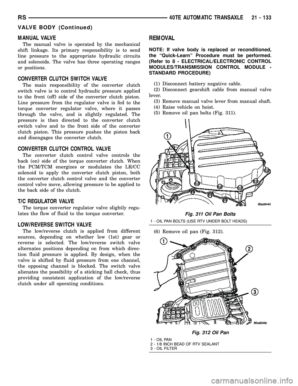
(5) Remove oil pan bolts (Fig. 311).
(6) Remove oil pan (Fig. 312).
Fig. 311 Oil Pan Bolts
1 - OIL PAN BOLTS (USE RTV UNDER BOLT HEADS)
Fig. 312 Oil Pan
1 - OIL PAN
2 - 1/8 INCH BEAD OF RTV SEALANT
3 - OIL FILTER
RS40TE AUTOMATIC TRANSAXLE21 - 133
VALVE BODY (Continued)
Page 1596 of 2339

DISASSEMBLY
NOTE: If valve body assembly is being recondi-
tioned, the PCM/TCM Quick Learn Procedure must
be performed. (Refer to 8 - ELECTRICAL/ELEC-
TRONIC CONTROL MODULES/TRANSMISSION
CONTROL MODULE - STANDARD PROCEDURE)
(1) Remove manual shaft seal (Fig. 317).
(2) Remove Transmission Range Sensor retaining
screw (Fig. 318).(3) Remove Manual Shaft/Rooster Comb and
Transmission Range Sensor (Fig. 319).
(4) Remove 2/4 Accumulator Retaining Plate (Fig.
320).
Fig. 317 Manual Shaft Seal
1 - SEAL
2 - MANUAL SHAFT
Fig. 318 Remove Transmission Range Sensor
1 - TRANSMISSION RANGE SENSOR
2 - MANUAL VALVE CONTROL PIN
3 - RETAINING SCREW
Fig. 319 Manual Shaft/Rooster Comb and
Transmission Range Sensor
1 - TRANSMISSION RANGE SENSOR
2 - MANUAL SHAFT
3 - ROOSTER COMB
Fig. 320 2/4 Accumulator Retaining Plate
1 - 2±4 ACCUMULATOR RETAINING PLATE
2 - DETENT SPRING
RS40TE AUTOMATIC TRANSAXLE21 - 135
VALVE BODY (Continued)
Page 1600 of 2339
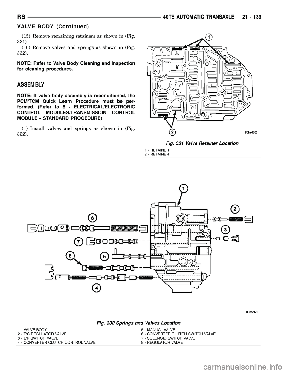
(15) Remove remaining retainers as shown in (Fig.
331).
(16) Remove valves and springs as shown in (Fig.
332).
NOTE: Refer to Valve Body Cleaning and Inspection
for cleaning procedures.
ASSEMBLY
NOTE: If valve body assembly is reconditioned, the
PCM/TCM Quick Learn Procedure must be per-
formed. (Refer to 8 - ELECTRICAL/ELECTRONIC
CONTROL MODULES/TRANSMISSION CONTROL
MODULE - STANDARD PROCEDURE)
(1) Install valves and springs as shown in (Fig.
332).
Fig. 331 Valve Retainer Location
1 - RETAINER
2 - RETAINER
Fig. 332 Springs and Valves Location
1 - VALVE BODY 5 - MANUAL VALVE
2 - T/C REGULATOR VALVE 6 - CONVERTER CLUTCH SWITCH VALVE
3 - L/R SWITCH VALVE 7 - SOLENOID SWITCH VALVE
4 - CONVERTER CLUTCH CONTROL VALVE 8 - REGULATOR VALVE
RS40TE AUTOMATIC TRANSAXLE21 - 139
VALVE BODY (Continued)
Page 1608 of 2339
VALVE BODY
DESCRIPTION........................283
OPERATION..........................283
REMOVAL............................284DISASSEMBLY........................286
ASSEMBLY...........................291
INSTALLATION........................295
41TE AUTOMATIC
TRANSAXLE
DESCRIPTION
The 41TE (Fig. 1) is a four-speed transaxle that is
a conventional hydraulic/mechanical assembly with
an integral differential, and is controlled with adap-
tive electronic controls and monitors. The hydraulic
system of the transaxle consists of the transaxle
fluid, fluid passages, hydraulic valves, and various
line pressure control components. An input clutch
assembly which houses the underdrive, overdrive,
and reverse clutches is used. It also utilizes separate
holding clutches: 2nd/4th gear and Low/Reverse. The
primary mechanical components of the transaxle con-
sist of the following:
²Three multiple disc input clutches
²Two multiple disc holding clutches
²Four hydraulic accumulators
²Two planetary gear sets
²Hydraulic oil pump
²Valve body²Solenoid/Pressure switch assembly
²Integral differential assembly
Control of the transaxle is accomplished by fully
adaptive electronics. Optimum shift scheduling is
accomplished through continuous real-time sensor
feedback information provided to the Powertrain
Control Module (PCM) or Transmission Control Mod-
ule (TCM).
The PCM/TCM is the heart of the electronic control
system and relies on information from various direct
and indirect inputs (sensors, switches, etc.) to deter-
mine driver demand and vehicle operating condi-
tions. With this information, the PCM/TCM can
calculate and perform timely and quality shifts
through various output or control devices (solenoid
pack, transmission control relay, etc.).
The PCM/TCM also performs certain self-diagnos-
tic functions and provides comprehensive information
(sensor data, DTC's, etc.) which is helpful in proper
diagnosis and repair. This information can be viewed
with the DRB scan tool.
RS41TE AUTOMATIC TRANSAXLE21 - 147
Page 1612 of 2339
Attach 300 psi gauge (C-3293SP) to port(s)
required for test(s) being conducted. Use adapter set
L-4559 to adapt gauge(s) to transaxle.
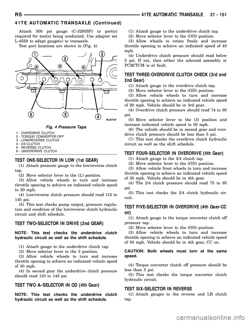
Test port locations are shown in (Fig. 4).
TEST ONE-SELECTOR IN LOW (1st GEAR)
(1) Attach pressure gauge to the low/reverse clutch
tap.
(2) Move selector lever to the (L) position.
(3) Allow vehicle wheels to turn and increase
throttle opening to achieve an indicated vehicle speed
to 20 mph.
(4) Low/reverse clutch pressure should read 115 to
145 psi.
(5) This test checks pump output, pressure regula-
tion and condition of the low/reverse clutch hydraulic
circuit and shift schedule.
TEST TWO-SELECTOR IN DRIVE (2nd GEAR)
NOTE: This test checks the underdrive clutch
hydraulic circuit as well as the shift schedule.
(1) Attach gauge to the underdrive clutch tap.
(2) Move selector lever to the 3 position.
(3) Allow vehicle wheels to turn and increase
throttle opening to achieve an indicated vehicle speed
of 30 mph.
(4) In second gear the underdrive clutch pressure
should read 110 to 145 psi.
TEST TWO A±SELECTOR IN OD (4th Gear)
NOTE: This test checks the underdrive clutch
hydraulic circuit as well as the shift schedule.(1) Attach gauge to the underdrive clutch tap.
(2) Move selector lever to the (OD) position.
(3) Allow wheels to rotate freely and increase
throttle opening to achieve an indicated speed of 40
mph.
(4) Underdrive clutch pressure should read below
5 psi. If not, then either the solenoid assembly or
PCM/TCM is at fault.
TEST THREE-OVERDRIVE CLUTCH CHECK (3rd and
2nd Gear)
(1) Attach gauge to the overdrive clutch tap.
(2) Move selector lever to the (OD) position.
(3) Allow vehicle wheels to turn and increase
throttle opening to achieve an indicated vehicle speed
of 20 mph. Vehicle should be in 3rd gear.
(4) Overdrive clutch pressure should read 74 to 95
psi.
(5) Move selector lever to the (3) position and
increase indicated vehicle speed to 30 mph.
(6) The vehicle should be in second gear and over-
drive clutch pressure should be less than 5 psi.
(7) This test checks the overdrive clutch hydraulic
circuit as well as the shift schedule.
TEST FOUR-SELECTOR IN OVERDRIVE (4th Gear)
(1) Attach gauge to the 2/4 clutch tap.
(2) Move selector lever to the (OD) position.
(3) Allow vehicle front wheels to turn and increase
throttle opening to achieve an indicated vehicle speed
of 30 mph. Vehicle should be in 4th gear.
(4) The 2/4 clutch pressure should read 75 to 95
psi.
(5) This test checks the 2/4 clutch hydraulic cir-
cuit.
TEST FIVE-SELECTOR IN OVERDRIVE (4th Gear-CC
on)
(1) Attach gauge to the torque converter clutch off
pressure tap.
(2) Move selector lever to the (OD) position.
(3) Allow vehicle wheels to turn and increase
throttle opening to achieve an indicated vehicle speed
of 50 mph. Vehicle should be in 4th gear, CC on.
CAUTION: Both wheels must turn at the same
speed.
(4) Torque converter clutch off pressure should be
less than 5 psi.
(5) This test checks the torque converter clutch
hydraulic circuit.
TEST SIX-SELECTOR IN REVERSE
(1) Attach gauges to the reverse and LR clutch
tap.
Fig. 4 Pressure Taps
1 - OVERDRIVE CLUTCH
2 - TORQUE CONVERTER OFF
3 - LOW/REVERSE CLUTCH
4 - 2/4 CLUTCH
5 - REVERSE CLUTCH
6 - UNDERDRIVE CLUTCH
RS41TE AUTOMATIC TRANSAXLE21 - 151
41TE AUTOMATIC TRANSAXLE (Continued)
Page 1613 of 2339
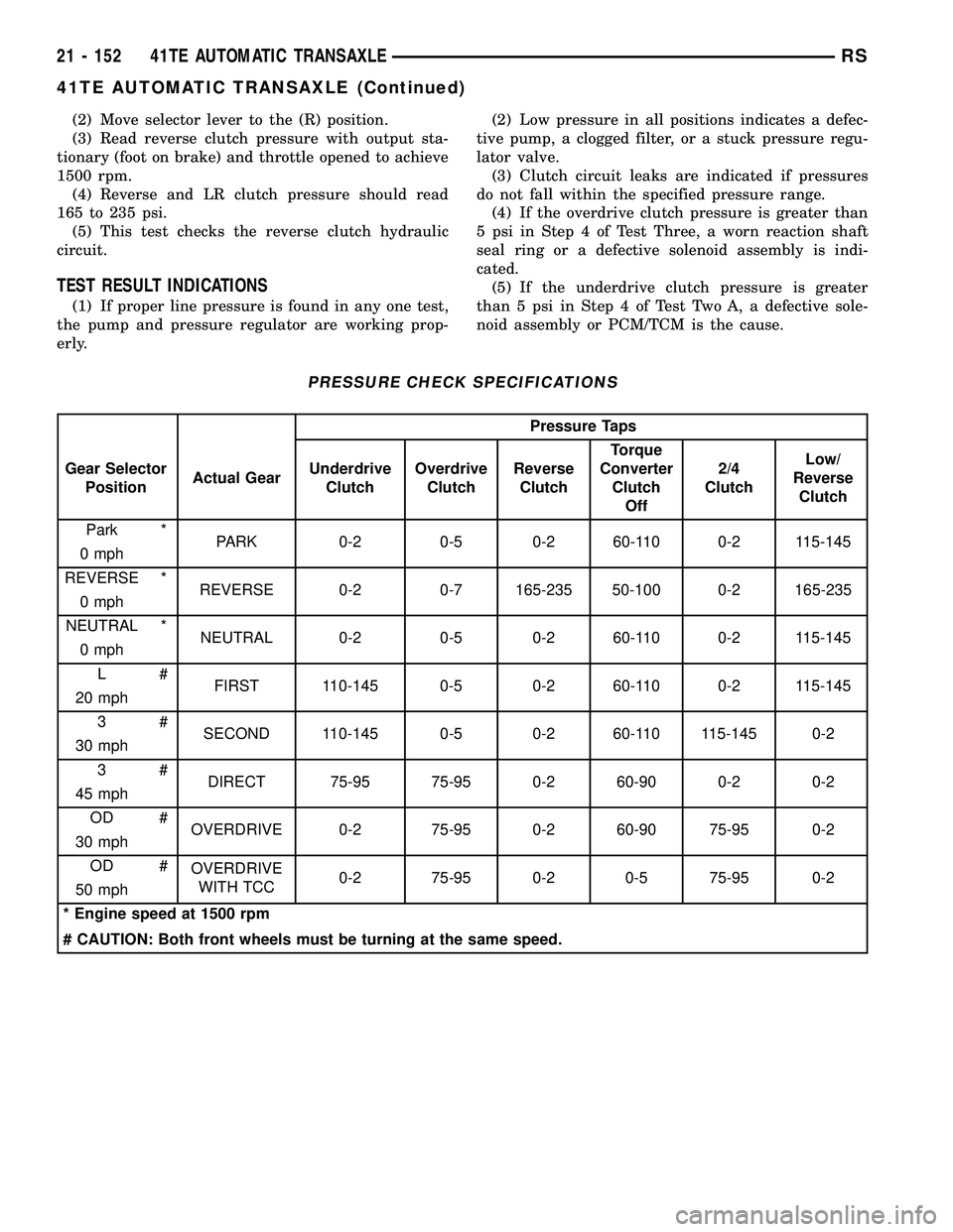
(2) Move selector lever to the (R) position.
(3) Read reverse clutch pressure with output sta-
tionary (foot on brake) and throttle opened to achieve
1500 rpm.
(4) Reverse and LR clutch pressure should read
165 to 235 psi.
(5) This test checks the reverse clutch hydraulic
circuit.
TEST RESULT INDICATIONS
(1) If proper line pressure is found in any one test,
the pump and pressure regulator are working prop-
erly.(2) Low pressure in all positions indicates a defec-
tive pump, a clogged filter, or a stuck pressure regu-
lator valve.
(3) Clutch circuit leaks are indicated if pressures
do not fall within the specified pressure range.
(4) If the overdrive clutch pressure is greater than
5 psi in Step 4 of Test Three, a worn reaction shaft
seal ring or a defective solenoid assembly is indi-
cated.
(5) If the underdrive clutch pressure is greater
than 5 psi in Step 4 of Test Two A, a defective sole-
noid assembly or PCM/TCM is the cause.
PRESSURE CHECK SPECIFICATIONS
Pressure Taps
Gear Selector
PositionActual GearUnderdrive
ClutchOverdrive
ClutchReverse
ClutchTorque
Converter
Clutch
Off2/4
ClutchLow/
Reverse
Clutch
Park *
PARK 0-2 0-5 0-2 60-110 0-2 115-145
0 mph
REVERSE *
REVERSE 0-2 0-7 165-235 50-100 0-2 165-235
0 mph
NEUTRAL *
NEUTRAL 0-2 0-5 0-2 60-110 0-2 115-145
0 mph
L#
FIRST 110-145 0-5 0-2 60-110 0-2 115-145
20 mph
3#
SECOND 110-145 0-5 0-2 60-110 115-145 0-2
30 mph
3#
DIRECT 75-95 75-95 0-2 60-90 0-2 0-2
45 mph
OD #
OVERDRIVE 0-2 75-95 0-2 60-90 75-95 0-2
30 mph
OD #
OVERDRIVE
WITH TCC0-2 75-95 0-2 0-5 75-95 0-2
50 mph
* Engine speed at 1500 rpm
# CAUTION: Both front wheels must be turning at the same speed.
21 - 152 41TE AUTOMATIC TRANSAXLERS
41TE AUTOMATIC TRANSAXLE (Continued)