clock CHRYSLER VOYAGER 2005 Service Manual
[x] Cancel search | Manufacturer: CHRYSLER, Model Year: 2005, Model line: VOYAGER, Model: CHRYSLER VOYAGER 2005Pages: 2339, PDF Size: 59.69 MB
Page 64 of 2339
(10) Remove the dust shield and jounce bumper as
an assembly from the strut shaft by pulling both
straight up and off the strut shaft. The dust shield
cannot be separated from the jounce bumper until
after it is removed from strut shaft.
(11) Remove the jounce bumper from the dust
shield. The jounce bumper is removed from the dust
shield by collapsing the dust shield until the jounce
bumper can be pulled free from the dust boot.
(12) Remove the spring isolator from the lower
spring seat on the strut (Fig. 38).
(13) Inspect the strut assembly components (Fig.
38) for the following and replace as necessary:
²Inspect the strut for any condition of shaft bind-
ing over the full stroke of the shaft.
²Check the upper mount for cracks and distortion
and its retaining studs for any sign of damage.
²Check the upper seat for stress cracks and wear.
²Check the upper spring isolator for severe dete-
rioration.
²Check for binding of the strut assembly pivot
bearing.
²Inspect the dust shield for rips and deteriora-
tion.
²Inspect the jounce bumper for cracks and signs
of deterioration.
ASSEMBLY - STRUT ASSEMBLY
For the disassembly and assembly of the strut
assembly, use of Strut Spring Compressor, Pentastar
Service Equipment (PSE) tool W-7200, or the equiva-
lent, is recommended to compress the coil spring.
Follow the manufacturer's instructions closely.
NOTE: Coil Springs on this vehicle are side-ori-
ented. Springs on the left side of the vehicle have a
left-hand wind top-to-bottom while springs on the
right side have a right-hand wind top-to-bottom.
Left and right springs must not be interchanged.
NOTE: If the coil spring has been removed from the
spring compressor, proceed with the next step, oth-
erwise, proceed with step 5.
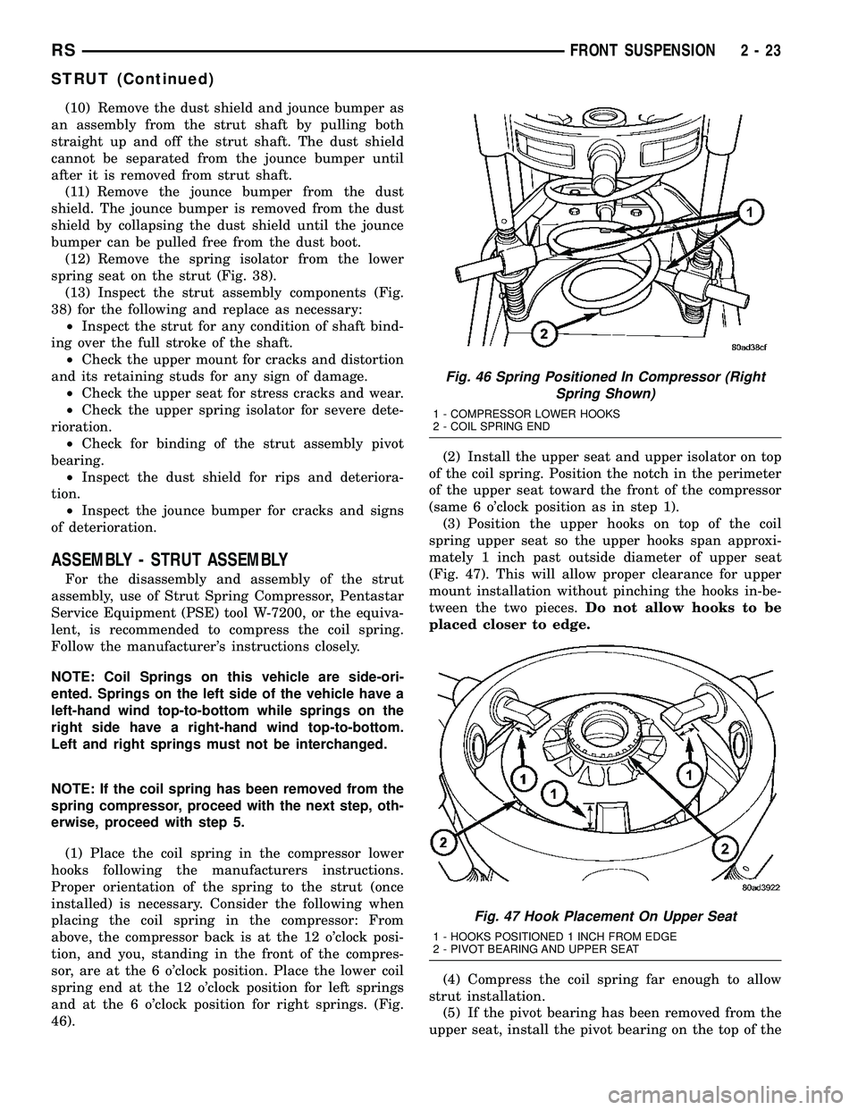
(1) Place the coil spring in the compressor lower
hooks following the manufacturers instructions.
Proper orientation of the spring to the strut (once
installed) is necessary. Consider the following when
placing the coil spring in the compressor: From
above, the compressor back is at the 12 o'clock posi-
tion, and you, standing in the front of the compres-
sor, are at the 6 o'clock position. Place the lower coil
spring end at the 12 o'clock position for left springs
and at the 6 o'clock position for right springs. (Fig.
46).(2) Install the upper seat and upper isolator on top
of the coil spring. Position the notch in the perimeter
of the upper seat toward the front of the compressor
(same 6 o'clock position as in step 1).
(3) Position the upper hooks on top of the coil
spring upper seat so the upper hooks span approxi-
mately 1 inch past outside diameter of upper seat
(Fig. 47). This will allow proper clearance for upper
mount installation without pinching the hooks in-be-
tween the two pieces.Do not allow hooks to be
placed closer to edge.
(4) Compress the coil spring far enough to allow
strut installation.
(5) If the pivot bearing has been removed from the
upper seat, install the pivot bearing on the top of the
Fig. 46 Spring Positioned In Compressor (Right
Spring Shown)
1 - COMPRESSOR LOWER HOOKS
2 - COIL SPRING END
Fig. 47 Hook Placement On Upper Seat
1 - HOOKS POSITIONED 1 INCH FROM EDGE
2 - PIVOT BEARING AND UPPER SEAT
RSFRONT SUSPENSION2-23
STRUT (Continued)
Page 65 of 2339
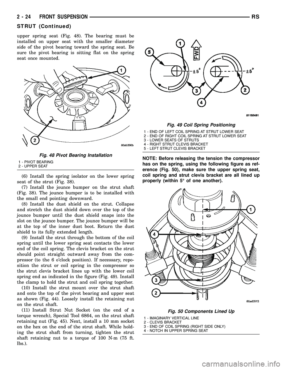
upper spring seat (Fig. 48). The bearing must be
installed on upper seat with the smaller diameter
side of the pivot bearing toward the spring seat. Be
sure the pivot bearing is sitting flat on the spring
seat once mounted.
(6) Install the spring isolator on the lower spring
seat of the strut (Fig. 38).
(7) Install the jounce bumper on the strut shaft
(Fig. 38). The jounce bumper is to be installed with
the small end pointing downward.
(8) Install the dust shield on the strut. Collapse
and stretch the dust shield down over the top of the
jounce bumper until the dust shield snaps into the
slot on the jounce bumper. The jounce bumper will be
at the top of the inner dust boot. Return the dust
shield to its fully extended length.
(9) Install the strut through the bottom of the coil
spring until the lower spring seat contacts the lower
end of the coil spring. The clevis bracket on the strut
should point straight outward away from the com-
pressor (to the 6 o'clock position). If necessary, repo-
sition the strut or coil spring in the compressor so
the strut clevis bracket lines up with the lower coil
spring end as indicated in the figure (Fig. 49). Install
the clamp to hold the strut and coil spring together.
(10) Install the strut mount over the strut shaft
and onto the top of the pivot bearing and upper seat
as shown (Fig. 44). Loosely install the retaining nut
on the strut shaft.
(11) Install Strut Nut Socket (on the end of a
torque wrench), Special Tool 6864, on the strut shaft
retaining nut (Fig. 45). Next, install a 10 mm socket
on the hex on the end of the strut shaft. While hold-
ing the strut shaft from turning, tighten the strut
shaft retaining nut to a torque of 100 N´m (75 ft.
lbs.).NOTE: Before releasing the tension the compressor
has on the spring, using the following figure as ref-
erence (Fig. 50), make sure the upper spring seat,
coil spring and strut clevis bracket are all lined up
properly (within 5É of one another).
Fig. 48 Pivot Bearing Installation
1 - PIVOT BEARING
2 - UPPER SEAT
Fig. 49 Coil Spring Positioning
1 - END OF LEFT COIL SPRING AT STRUT LOWER SEAT
2 - END OF RIGHT COIL SPRING AT STRUT LOWER SEAT
3 - LOWER SEATS OF STRUTS
4 - RIGHT STRUT CLEVIS BRACKET
5 - LEFT STRUT CLEVIS BRACKET
Fig. 50 Components Lined Up
1 - IMAGINARY VERTICAL LINE
2 - CLEVIS BRACKET
3 - END OF COIL SPRING (RIGHT SIDE ONLY)
4 - NOTCH IN UPPER SPRING SEAT
2 - 24 FRONT SUSPENSIONRS
STRUT (Continued)
Page 77 of 2339
REMOVAL
REMOVAL - AWD, HEAVY DUTY, CARGO
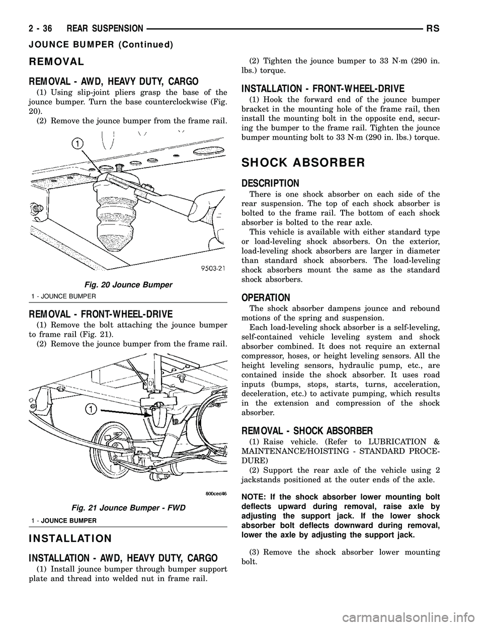
(1) Using slip-joint pliers grasp the base of the
jounce bumper. Turn the base counterclockwise (Fig.
20).
(2) Remove the jounce bumper from the frame rail.
REMOVAL - FRONT-WHEEL-DRIVE
(1) Remove the bolt attaching the jounce bumper
to frame rail (Fig. 21).
(2) Remove the jounce bumper from the frame rail.
INSTALLATION
INSTALLATION - AWD, HEAVY DUTY, CARGO
(1) Install jounce bumper through bumper support
plate and thread into welded nut in frame rail.(2) Tighten the jounce bumper to 33 N´m (290 in.
lbs.) torque.
INSTALLATION - FRONT-WHEEL-DRIVE
(1) Hook the forward end of the jounce bumper
bracket in the mounting hole of the frame rail, then
install the mounting bolt in the opposite end, secur-
ing the bumper to the frame rail. Tighten the jounce
bumper mounting bolt to 33 N´m (290 in. lbs.) torque.
SHOCK ABSORBER
DESCRIPTION
There is one shock absorber on each side of the
rear suspension. The top of each shock absorber is
bolted to the frame rail. The bottom of each shock
absorber is bolted to the rear axle.
This vehicle is available with either standard type
or load-leveling shock absorbers. On the exterior,
load-leveling shock absorbers are larger in diameter
than standard shock absorbers. The load-leveling
shock absorbers mount the same as the standard
shock absorbers.
OPERATION
The shock absorber dampens jounce and rebound
motions of the spring and suspension.
Each load-leveling shock absorber is a self-leveling,
self-contained vehicle leveling system and shock
absorber combined. It does not require an external
compressor, hoses, or height leveling sensors. All the
height leveling sensors, hydraulic pump, etc., are
contained inside the shock absorber. It uses road
inputs (bumps, stops, starts, turns, acceleration,
deceleration, etc.) to activate pumping, which results
in the extension and compression of the shock
absorber.
REMOVAL - SHOCK ABSORBER
(1) Raise vehicle. (Refer to LUBRICATION &
MAINTENANCE/HOISTING - STANDARD PROCE-
DURE)
(2) Support the rear axle of the vehicle using 2
jackstands positioned at the outer ends of the axle.
NOTE: If the shock absorber lower mounting bolt
deflects upward during removal, raise axle by
adjusting the support jack. If the lower shock
absorber bolt deflects downward during removal,
lower the axle by adjusting the support jack.
(3) Remove the shock absorber lower mounting
bolt.
Fig. 20 Jounce Bumper
1 - JOUNCE BUMPER
Fig. 21 Jounce Bumper - FWD
1-JOUNCE BUMPER
2 - 36 REAR SUSPENSIONRS
JOUNCE BUMPER (Continued)
Page 152 of 2339
(12) Disconnect wiring harness connectors (as
equipped) from clockspring, multi-function switch,
SKIM module, ignition switch and BTSI solenoid.
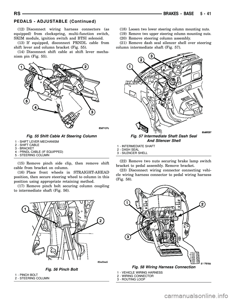
(13) If equipped, disconnect PRNDL cable from
shift lever and column bracket (Fig. 55).
(14) Disconnect shift cable at shift lever mecha-
nism pin (Fig. 55).
(15) Remove pinch side clip, then remove shift
cable from bracket on column.
(16) Place front wheels in STRAIGHT-AHEAD
position, then secure steering wheel to column in this
position using appropriate retaining method.
(17) Remove pinch bolt securing column coupling
to intermediate shaft (Fig. 56).(18)Loosen two lower steering column mounting nuts.
(19)Remove two upper steering column mounting nuts.
(20) Remove steering column assembly.
(21) Remove dash seal silencer shell over steering
column intermediate shaft (Fig. 57).
(22) Remove two nuts securing brake lamp switch
bracket to pedal assembly. Remove bracket.
(23) Disconnect wiring connector connecting vehi-
cle wiring harness connector to pedal wiring harness
(Fig. 58).
Fig. 55 Shift Cable At Steering Column
1 - SHIFT LEVER MECHANISM
2 - SHIFT CABLE
3 - BRACKET
4 - PRNDL CABLE (IF EQUIPPED)
5 - STEERING COLUMN
Fig. 56 Pinch Bolt
1 - PINCH BOLT
2 - STEERING COLUMN
Fig. 57 Intermediate Shaft Dash Seal
And Silencer Shell
1 - INTERMEDIATE SHAFT
2 - DASH SEAL
3 - SILENCER SHELL
Fig. 58 Wiring Harness Connection
1 - VEHICLE WIRING HARNESS
2 - WIRING CONNECTOR
3 - ROUTING LOOP
RSBRAKES - BASE5-41
PEDALS - ADJUSTABLE (Continued)
Page 154 of 2339
INSTALLATION
(1) Install adjustable pedals assembly under
instrument panel.
(2) Attach throttle cable to accelerator pedal using
cable retainer.
(3) Install two upper mounting bolts attaching
pedals assembly to steering column support bracket
on dash panel.Do not fully tighten at this time.
(4) Install four nuts attaching pedals assembly and
power brake booster to dash panel (Fig. 61).
(5) Tighten four booster mounting nuts and two
upper mounting bolts to 28 N´m (21 ft. lbs.) torque.
(6) Route pedal adjuster cable up and over right
side of pedals assembly and steering column bracket,
then down through hole in steering column bracket
as shown (Fig. 60). Attach end of cable to gear box.
(7) Place adjuster cable through loop on right side
of steering column bracket as shown (Fig. 60).
(8) Install booster input rod onto brake pedal pin
and install a NEW retaining clip.
(9) Connect wiring connector connecting vehicle
wiring harness to pedal wiring harness (Fig. 58).
(10) Connect routing clips retaining vehicle wiring
harness to pedal wiring harness (Fig. 58).
(11) Install brake lamp switch bracket on pedals
assembly. Tighten mounting nuts to 6 N´m (50 in.
lbs.) torque.
(12) Install dash seal silencer shell over steering
column intermediate shaft and fasten in place (Fig.
57).
(13) Install steering column onto lower mounting
studs with nuts started, then install column onto
upper mounting studs and install two upper mount-
ing nuts. Tighten upper, then lower mounting nuts to
12 N´m (105 in. lbs.) torque.
(14) Install column shaft coupling onto intermedi-
ate shaft and install pinch bolt. Make sure rounded
side of intermediate shaft is matched to the curva-
ture of the coupling. Tighten pinch bolt to 28 N´m
(250 in. lbs.) torque.
(15) Remove retainer holding steering wheel in
place on steering column.
(16) Attach shift cable to bracket on column.
(17) Connect shift cable end to shift lever mecha-
nism pin (Fig. 55).
(18) If equipped, connect PRNDL cable to end of
shift lever mechanism pin and column bracket (Fig.
55).(19) Connect column wiring harness connectors (as
equipped) to SKIM, BTSI solenoid, ignition switch,
multi-function switch, and clockspring.
(20) Install lower and upper steering column
shrouds. (Refer to 19 - STEERING/COLUMN/
LOWER SHROUD - INSTALLATION)
CAUTION: Do not reuse the original brake lamp
switch. The switch can only be adjusted once. That
is during initial installation of the switch. If the
switch is not adjusted properly or has been
removed for some service, a new switch must be
installed and adjusted.
(21) Install and adjust NEW brake lamp switch.
(Refer to 8 - ELECTRICAL/LAMPS/LIGHTING -
EXTERIOR/BRAKE LAMP SWITCH - INSTALLA-
TION)
(22) Install instrument panel lower left reinforce-
ment (Fig. 54).
(23) Attach hood release to lower left reinforce-
ment.
(24) Install knee blocker reinforcement plate (Fig.
53).
(25) Connect parking brake release link to release
handle.
(26) Install data link diagnostic connector to
mounting hole in reinforcement plate.
(27) Install lower steering column cover/knee
blocker (Fig. 53).
(28) Install throttle cable onto throttle body lever.
(Refer to 14 - FUEL SYSTEM/FUEL INJECTION/
THROTTLE CONTROL CABLE - INSTALLATION)
NOTE: When reconnecting the battery on a vehicle
that has had the airbag module removed, the fol-
lowing procedure should be used.
(29) Reconnect ground cable to negative post of
battery following special Diagnosis And Testing pro-
cedure. (Refer to 8 - ELECTRICAL/RESTRAINTS -
DIAGNOSIS AND TESTING)
(30) Test operation of adjustable pedals and all
functions that are steering column operated. If appli-
cable, reset radio and clock.
(31) Road test the vehicle to ensure proper opera-
tion of steering and brake systems.
RSBRAKES - BASE5-43
PEDALS - ADJUSTABLE (Continued)
Page 176 of 2339
the park brake in this position, install a pair of lock-
ing pliers on the front parking brake cable just rear-
ward of the second body outrigger bracket (Fig. 97).
(2) Install the equalizer on the front parking brake
cable.
(3) Install the left rear and intermediate park
brake cable in the correct location on the parking
brake cable equalizer (Fig. 98).
(4) Remove the locking pliers from the front park-
ing brake cable. This will allow the adjuster in the
park brake lever (pedal) mechanism to tension the
park brake cables.
(5) Apply and release the parking brake lever
(pedal) one time. This will seat the parking brake
cables and allow the auto adjuster in the parking
brake lever (pedal) mechanism to correctly tension
the parking brake cables.
STANDARD PROCEDURE - CABLE END
CLEANING AND LUBRICATION
Periodic cleaning and lubrication can be done to
ensure proper operation of the parking brake cables.This procedure applies to the trailing end of all park-
ing brake cables.
CAUTION: If a liquid cleaner is necessary, use a
cleaner such as MoparTNon-Chlorinated Brake
Parts Cleaner or equivalent.
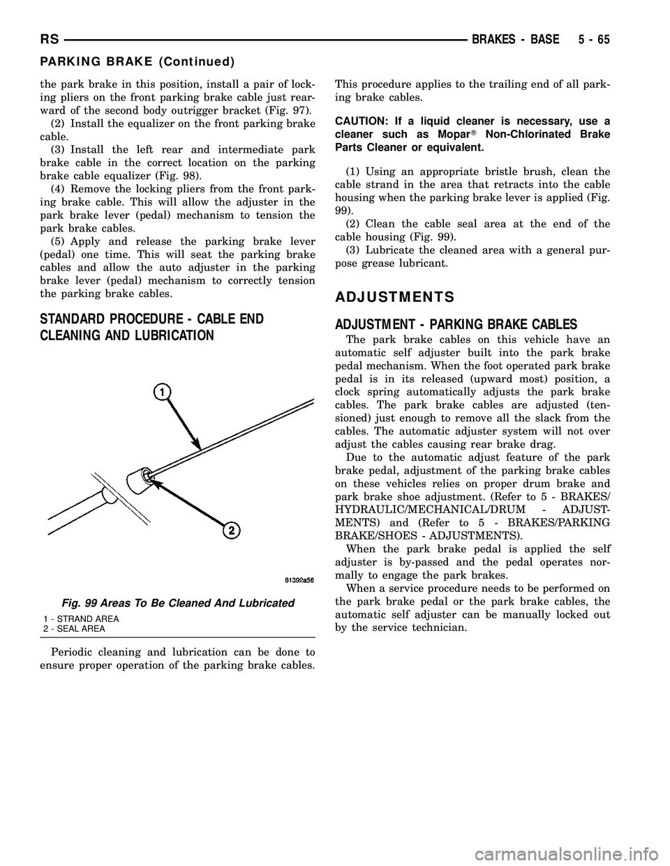
(1) Using an appropriate bristle brush, clean the
cable strand in the area that retracts into the cable
housing when the parking brake lever is applied (Fig.
99).
(2) Clean the cable seal area at the end of the
cable housing (Fig. 99).
(3) Lubricate the cleaned area with a general pur-
pose grease lubricant.
ADJUSTMENTS
ADJUSTMENT - PARKING BRAKE CABLES
The park brake cables on this vehicle have an
automatic self adjuster built into the park brake
pedal mechanism. When the foot operated park brake
pedal is in its released (upward most) position, a
clock spring automatically adjusts the park brake
cables. The park brake cables are adjusted (ten-
sioned) just enough to remove all the slack from the
cables. The automatic adjuster system will not over
adjust the cables causing rear brake drag.
Due to the automatic adjust feature of the park
brake pedal, adjustment of the parking brake cables
on these vehicles relies on proper drum brake and
park brake shoe adjustment. (Refer to 5 - BRAKES/
HYDRAULIC/MECHANICAL/DRUM - ADJUST-
MENTS) and (Refer to 5 - BRAKES/PARKING
BRAKE/SHOES - ADJUSTMENTS).
When the park brake pedal is applied the self
adjuster is by-passed and the pedal operates nor-
mally to engage the park brakes.
When a service procedure needs to be performed on
the park brake pedal or the park brake cables, the
automatic self adjuster can be manually locked out
by the service technician.
Fig. 99 Areas To Be Cleaned And Lubricated
1 - STRAND AREA
2 - SEAL AREA
RSBRAKES - BASE5-65
PARKING BRAKE (Continued)
Page 228 of 2339
REMOVAL
GENERATOR AND AIR CONDITIONING BELT
(1) Raise vehicle on hoist.
(2) Remove the drive belt shield (Fig. 8).
WARNING: DO NOT ALLOW DRIVE BELT TEN-
SIONER TO SNAP BACK, AS DAMAGE TO TEN-
SIONER AND/OR PERSONAL INJURY COULD
RESULT.
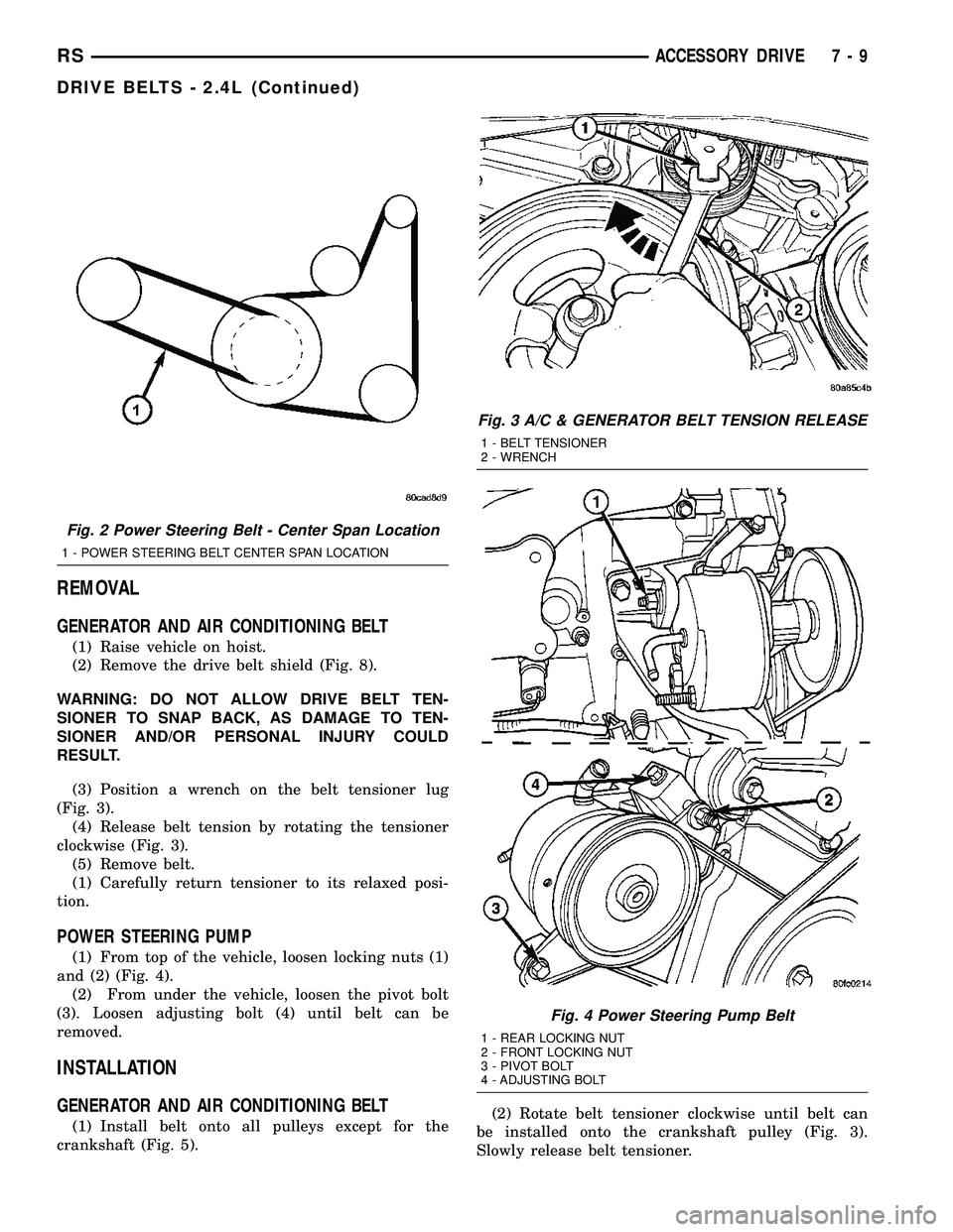
(3) Position a wrench on the belt tensioner lug
(Fig. 3).
(4) Release belt tension by rotating the tensioner
clockwise (Fig. 3).
(5) Remove belt.
(1) Carefully return tensioner to its relaxed posi-
tion.
POWER STEERING PUMP
(1) From top of the vehicle, loosen locking nuts (1)
and (2) (Fig. 4).
(2) From under the vehicle, loosen the pivot bolt
(3). Loosen adjusting bolt (4) until belt can be
removed.
INSTALLATION
GENERATOR AND AIR CONDITIONING BELT
(1) Install belt onto all pulleys except for the
crankshaft (Fig. 5).(2) Rotate belt tensioner clockwise until belt can
be installed onto the crankshaft pulley (Fig. 3).
Slowly release belt tensioner.
Fig. 2 Power Steering Belt - Center Span Location
1 - POWER STEERING BELT CENTER SPAN LOCATION
Fig. 3 A/C & GENERATOR BELT TENSION RELEASE
1 - BELT TENSIONER
2 - WRENCH
Fig. 4 Power Steering Pump Belt
1 - REAR LOCKING NUT
2 - FRONT LOCKING NUT
3 - PIVOT BOLT
4 - ADJUSTING BOLT
RSACCESSORY DRIVE7-9
DRIVE BELTS - 2.4L (Continued)
Page 230 of 2339
BELT TENSIONER - 2.4L
REMOVAL
(1) Raise vehicle on hoist.
(2) Remove the drive belt shield.
(3) Remove the generator/A/C drive belt. (Refer to
7 - COOLING/ACCESSORY DRIVE/DRIVE BELTS -
REMOVAL)
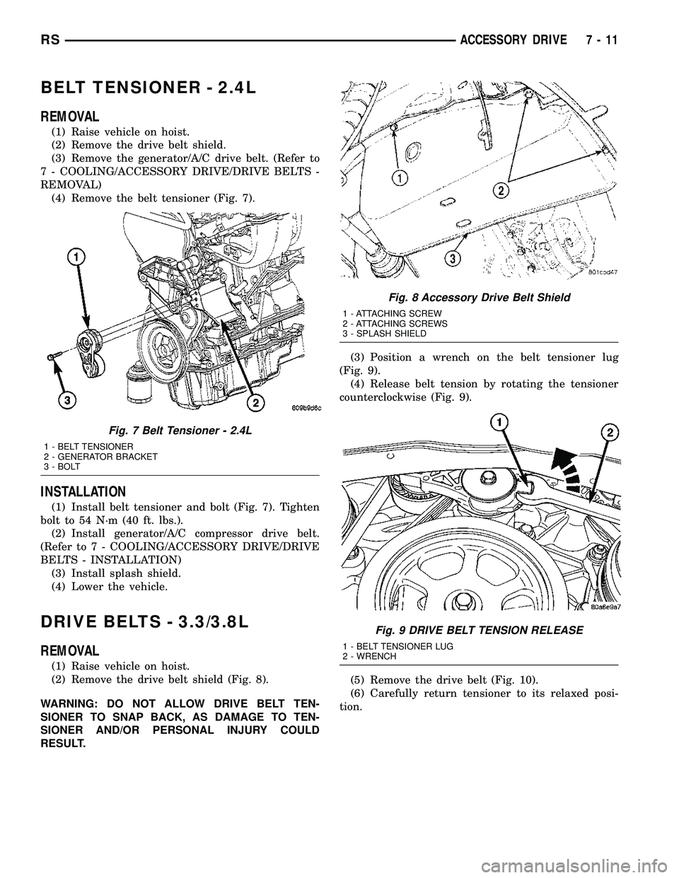
(4) Remove the belt tensioner (Fig. 7).
INSTALLATION
(1) Install belt tensioner and bolt (Fig. 7). Tighten
bolt to 54 N´m (40 ft. lbs.).
(2) Install generator/A/C compressor drive belt.
(Refer to 7 - COOLING/ACCESSORY DRIVE/DRIVE
BELTS - INSTALLATION)
(3) Install splash shield.
(4) Lower the vehicle.
DRIVE BELTS - 3.3/3.8L
REMOVAL
(1) Raise vehicle on hoist.
(2) Remove the drive belt shield (Fig. 8).
WARNING: DO NOT ALLOW DRIVE BELT TEN-
SIONER TO SNAP BACK, AS DAMAGE TO TEN-
SIONER AND/OR PERSONAL INJURY COULD
RESULT.(3) Position a wrench on the belt tensioner lug
(Fig. 9).
(4) Release belt tension by rotating the tensioner
counterclockwise (Fig. 9).
(5) Remove the drive belt (Fig. 10).
(6) Carefully return tensioner to its relaxed posi-
tion.
Fig. 7 Belt Tensioner - 2.4L
1 - BELT TENSIONER
2 - GENERATOR BRACKET
3 - BOLT
Fig. 8 Accessory Drive Belt Shield
1 - ATTACHING SCREW
2 - ATTACHING SCREWS
3 - SPLASH SHIELD
Fig. 9 DRIVE BELT TENSION RELEASE
1 - BELT TENSIONER LUG
2 - WRENCH
RSACCESSORY DRIVE7-11
Page 231 of 2339
INSTALLATION
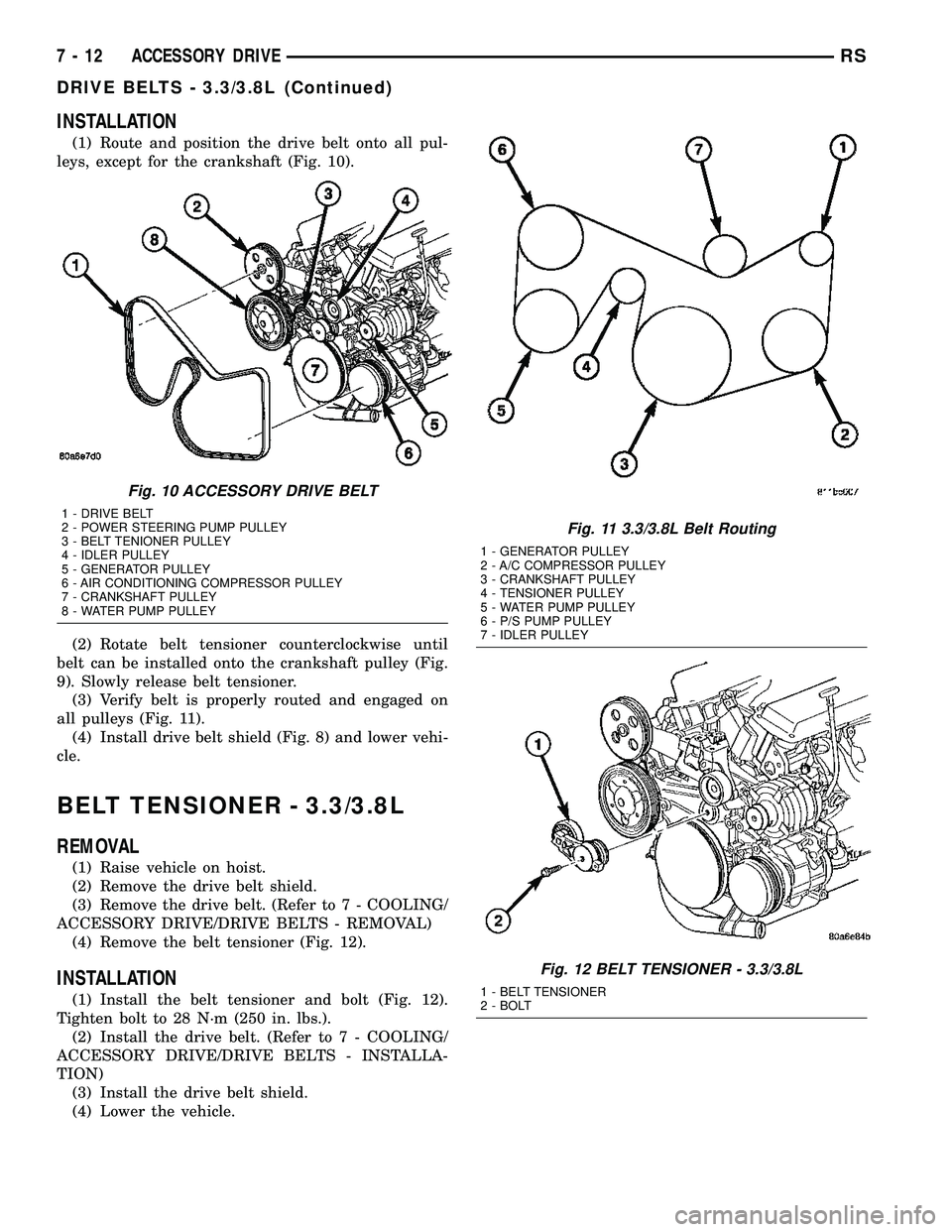
(1) Route and position the drive belt onto all pul-
leys, except for the crankshaft (Fig. 10).
(2) Rotate belt tensioner counterclockwise until
belt can be installed onto the crankshaft pulley (Fig.
9). Slowly release belt tensioner.
(3) Verify belt is properly routed and engaged on
all pulleys (Fig. 11).
(4) Install drive belt shield (Fig. 8) and lower vehi-
cle.
BELT TENSIONER - 3.3/3.8L
REMOVAL
(1) Raise vehicle on hoist.
(2) Remove the drive belt shield.
(3) Remove the drive belt. (Refer to 7 - COOLING/
ACCESSORY DRIVE/DRIVE BELTS - REMOVAL)
(4) Remove the belt tensioner (Fig. 12).
INSTALLATION
(1) Install the belt tensioner and bolt (Fig. 12).
Tighten bolt to 28 N´m (250 in. lbs.).
(2) Install the drive belt. (Refer to 7 - COOLING/
ACCESSORY DRIVE/DRIVE BELTS - INSTALLA-
TION)
(3) Install the drive belt shield.
(4) Lower the vehicle.
Fig. 10 ACCESSORY DRIVE BELT
1 - DRIVE BELT
2 - POWER STEERING PUMP PULLEY
3 - BELT TENIONER PULLEY
4 - IDLER PULLEY
5 - GENERATOR PULLEY
6 - AIR CONDITIONING COMPRESSOR PULLEY
7 - CRANKSHAFT PULLEY
8 - WATER PUMP PULLEY
Fig. 11 3.3/3.8L Belt Routing
1 - GENERATOR PULLEY
2 - A/C COMPRESSOR PULLEY
3 - CRANKSHAFT PULLEY
4 - TENSIONER PULLEY
5 - WATER PUMP PULLEY
6 - P/S PUMP PULLEY
7 - IDLER PULLEY
Fig. 12 BELT TENSIONER - 3.3/3.8L
1 - BELT TENSIONER
2 - BOLT
7 - 12 ACCESSORY DRIVERS
DRIVE BELTS - 3.3/3.8L (Continued)
Page 243 of 2339
ENGINE COOLANT
THERMOSTAT - 2.4L
REMOVAL
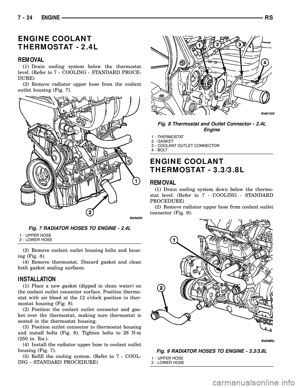
(1) Drain cooling system below the thermostat
level. (Refer to 7 - COOLING - STANDARD PROCE-
DURE)
(2) Remove radiator upper hose from the coolant
outlet housing (Fig. 7).
(3) Remove coolant outlet housing bolts and hous-
ing (Fig. 8).
(4) Remove thermostat. Discard gasket and clean
both gasket sealing surfaces.
INSTALLATION
(1) Place a new gasket (dipped in clean water) on
the coolant outlet connector surface. Position thermo-
stat with air bleed at the 12 o'clock position in ther-
mostat housing (Fig. 8).
(2) Position the coolant outlet connector and gas-
ket over the thermostat, making sure thermostat is
seated in the thermostat housing.
(3) Position outlet connector to thermostat housing
and install bolts (Fig. 8). Tighten bolts to 28 N´m
(250 in. lbs.).
(4) Install the radiator upper hose to coolant outlet
housing (Fig. 7).
(5) Refill the cooling system. (Refer to 7 - COOL-
ING - STANDARD PROCEDURE)
ENGINE COOLANT
THERMOSTAT - 3.3/3.8L
REMOVAL
(1) Drain cooling system down below the thermo-
stat level. (Refer to 7 - COOLING - STANDARD
PROCEDURE)
(2) Remove radiator upper hose from coolant outlet
connector (Fig. 9).
Fig. 7 RADIATOR HOSES TO ENGINE - 2.4L
1 - UPPER HOSE
2 - LOWER HOSE
Fig. 8 Thermostat and Outlet Connector - 2.4L
Engine
1 - THERMOSTAT
2 - GASKET
3 - COOLANT OUTLET CONNECTOR
4 - BOLT
Fig. 9 RADIATOR HOSES TO ENGINE - 3.3/3.8L
1 - UPPER HOSE
2 - LOWER HOSE
7 - 24 ENGINERS