exhaust CHRYSLER VOYAGER 2005 Owner's Manual
[x] Cancel search | Manufacturer: CHRYSLER, Model Year: 2005, Model line: VOYAGER, Model: CHRYSLER VOYAGER 2005Pages: 2339, PDF Size: 59.69 MB
Page 1203 of 2339
CYLINDER-TO-CYLINDER LEAKAGE TEST
To determine if an engine cylinder head gasket is
leaking between adjacent cylinders, follow the proce-
dures in Cylinder Compression Pressure Test (Refer
to 9 - ENGINE - DIAGNOSIS AND TESTING). An
engine cylinder head gasket leaking between adja-
cent cylinders will result in approximately a 50±70%
reduction in compression pressure.
CYLINDER-TO-WATER JACKET LEAKAGE TEST
WARNING: USE EXTREME CAUTION WHEN THE
ENGINE IS OPERATING WITH COOLANT PRES-
SURE CAP REMOVED.
VISUAL TEST METHOD
With the engine cool, remove the coolant pressure
cap. Start the engine and allow it to warm up until
thermostat opens.
If a large combustion/compression pressure leak
exists, bubbles will be visible in the coolant.
COOLING SYSTEM TESTER METHOD
WARNING: WITH COOLING SYSTEM TESTER IN
PLACE, PRESSURE WILL BUILD UP FAST. EXCES-
SIVE PRESSURE BUILT UP, BY CONTINUOUS
ENGINE OPERATION, MUST BE RELEASED TO A
SAFE PRESSURE POINT. NEVER PERMIT PRES-
SURE TO EXCEED 138 kPa (20 psi).
Install Cooling System Tester 7700 or equivalent to
pressure cap neck. Start the engine and observe the
tester's pressure gauge. If gauge pulsates with every
power stroke of a cylinder a combustion pressure
leak is evident.
CHEMICAL TEST METHOD
Combustion leaks into the cooling system can also
be checked by using Bloc-Chek Kit C-3685-A or
equivalent. Perform test following the procedures
supplied with the tool kit.
REMOVAL - CYLINDER HEAD
(1) Perform fuel system pressure release procedure
before attempting any repairs.(Refer to 14 -
FUEL SYSTEM/FUEL DELIVERY - SPECIFICA-
TIONS)
(2) Disconnect battery negative cable.
(3) Drain cooling system. (Refer to 7 - COOLING -
STANDARD PROCEDURE)
(4) Remove air filter housing and inlet tube.
(5) Remove upper intake manifold. (Refer to 9 -
ENGINE/MANIFOLDS/INTAKE MANIFOLD -
REMOVAL)(6) Remove heater tube support bracket from cyl-
inder head.
(7) Disconnect radiator upper and heater supply
hoses from intake manifold water outlet connections.
(8) Remove accessory drive belts. (Refer to 7 -
COOLING/ACCESSORY DRIVE/DRIVE BELTS -
REMOVAL)
(9) Raise vehicle and remove exhaust pipe from
manifold.
(10) Remove power steering pump reservoir and
line support bracket from lower intake manifold and
set aside. Do not disconnect lines.
(11) Remove ignition coil and wires from engine.
(12) Disconnect cam sensor and fuel injector wir-
ing connectors.
(13) Remove timing belt and camshaft sprockets.
(Refer to 9 - ENGINE/VALVE TIMING/TIMING
BELT/CHAIN AND SPROCKETS - REMOVAL)
(14) Remove timing belt idler pulley and rear tim-
ing belt cover. (Refer to 9 - ENGINE/VALVE TIM-
ING/TIMING BELT / CHAIN COVER(S) -
REMOVAL)
(15) Remove cylinder head cover. (Refer to 9 -
ENGINE/CYLINDER HEAD/CYLINDER HEAD
COVER(S) - REMOVAL)
(16) Remove camshafts (Refer to 9 - ENGINE/
CYLINDER HEAD/CAMSHAFT(S) - REMOVAL).
NOTE: Identify rocker arm position to ensure cor-
rect re-installation in original position, if reused.
(17) Remove rocker arms. (Refer to 9 - ENGINE/
CYLINDER HEAD/ROCKER ARMS - REMOVAL)
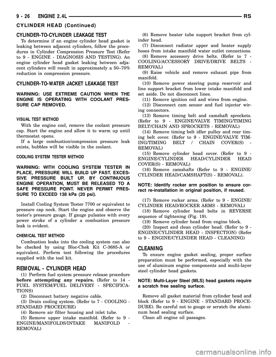
(18) Remove cylinder head bolts in REVERSE
sequence of tightening (Fig. 19).
(19) Remove cylinder head from engine block.
(20) Inspect and clean cylinder head. (Refer to 9 -
ENGINE/CYLINDER HEAD - INSPECTION) (Refer
to 9 - ENGINE/CYLINDER HEAD - CLEANING)
CLEANING
To ensure engine gasket sealing, proper surface
preparation must be performed, especially with the
use of aluminum engine components and multi-layer
steel cylinder head gaskets.
NOTE: Multi-Layer Steel (MLS) head gaskets require
a scratch free sealing surface.
Remove all gasket material from cylinder head and
block (Refer to 9 - ENGINE - STANDARD PROCE-
DURE). Be careful not to gouge or scratch the alumi-
num head sealing surface.
Clean all engine oil passages.
9 - 26 ENGINE 2.4LRS
CYLINDER HEAD (Continued)
Page 1205 of 2339

(5) Install rocker arms. (Refer to 9 - ENGINE/
CYLINDER HEAD/ROCKER ARMS - INSTALLA-
TION)
(6) Install camshafts. (Refer to 9 - ENGINE/CYL-
INDER HEAD/CAMSHAFT(S) - INSTALLATION).
(7) Install cylinder head cover. (Refer to 9 -
ENGINE/CYLINDER HEAD/CYLINDER HEAD
COVER(S) - INSTALLATION)
(8) Install timing belt rear cover and timing belt
idler pulley. (Refer to 9 - ENGINE/VALVE TIMING/
TIMING BELT / CHAIN COVER(S) - INSTALLA-
TION)
(9) Install timing belt and camshaft sprockets.
(Refer to 9 - ENGINE/VALVE TIMING/TIMING
BELT/CHAIN AND SPROCKETS - INSTALLATION)
(10) Connect cam sensor and fuel injectors wiring
connectors.
(11) Install ignition coil and wires. Connect igni-
tion coil wiring connector.
(12) Install power steering pump reservoir and
line support bracket to cylinder head.
(13) Raise vehicle and install the exhaust pipe to
the manifold.(14) Install accessory drive belts. (Refer to 7 -
COOLING/ACCESSORY DRIVE/DRIVE BELTS -
INSTALLATION)
(15) Install heater tube support bracket to cylinder
head.
(16) Connect radiator upper and heater hoses to
intake manifold water outlet connections.
(17) Install upper intake manifold. (Refer to 9 -
ENGINE/MANIFOLDS/INTAKE MANIFOLD -
INSTALLATION)
(18) Using new gaskets, install EGR tube and
tighten fasteners to 11 N´m (95 in. lbs.).
(19) Install air inlet tube and housing.
(20) Connect all vacuum lines, electrical wiring,
ground straps and fuel line.
(21) Fill cooling system. (Refer to 7 - COOLING -
STANDARD PROCEDURE)
(22) Connect battery negative cable.
CAMSHAFT OIL SEAL(S)
REMOVAL
(1) Remove timing belt (Refer to 9 - ENGINE/
VALVE TIMING/TIMING BELT AND SPROCKETS -
REMOVAL).
(2) Hold each camshaft sprocket with Special Tool
6847 while removing center bolt (Fig. 20).
(3) Remove camshaft sprockets.
(4) Remove rear timing belt cover (Refer to 9 -
ENGINE/VALVE TIMING/TIMING BELT COVER(S)
- REMOVAL).
(5) Remove camshaft seal using Special Tool
C-4679A (Fig. 21).
Fig. 18 Cylinder Head Gasket Positioning
1 - PART NUMBER FACES UP
2 - NO. 1 CYLINDER
Fig. 19 Cylinder Head Tightening Sequence
Fig. 20 Camshaft Sprocket - Removal/Installation
1 - SPECIAL TOOL 6847
9 - 28 ENGINE 2.4LRS
CYLINDER HEAD (Continued)
Page 1210 of 2339

INTAKE/EXHAUST VALVES &
SEATS
DESCRIPTION
The valves are made of heat resistant steel. They
have chrome plated stems to prevent scuffing. Viton
rubber valve stem seals are integral with the spring
seats. The valves have three-bead lock keepers to
retain springs and to promote valve rotation.
CLEANING
(1) Clean all valves thoroughly and discard
burned, warped and cracked valves.
VALVE SPRINGS & SEALS
REMOVAL
REMOVAL - CYLINDER HEAD ON
(1) Remove cylinder head cover (Refer to 9 -
ENGINE/CYLINDER HEAD/CYLINDER HEAD
COVER(S) - REMOVAL).
(2) Remove camshafts (Refer to 9 - ENGINE/CYL-
INDER HEAD/CAMSHAFT(S) - REMOVAL).
(3) Rotate crankshaft until piston is at TDC on
compression.
(4) With air hose attached to adapter tool installed
in spark plug hole, apply 90-120 psi air pressure.
(5) Using Special Tool MD-998772-A with adapter
6779 (Fig. 33), compress valve springs and remove
valve locks.
(6) Remove valve spring(s).
(7) Remove valve stem seal(s) by a using valve
stem seal tool (Fig. 35).
REMOVAL - CYLINDER HEAD OFF
(1) With cylinder head removed from cylinder
block, compress valve springs using a universal valve
spring compressor.
(2) Remove valve retaining locks, valve spring
retainers, valve stem seals and valve springs.
(3) Before removing valves,remove any burrs
from valve stem lock grooves to prevent dam-
age to the valve guides.Identify valves, locks and
retainers to insure installation in original location.
(4) Inspect the valves. (Refer to 9 - ENGINE/CYL-
INDER HEAD/VALVE SPRINGS - INSPECTION)
INSPECTION
(1) Whenever valves have been removed for inspec-
tion, reconditioning or replacement, valve springs
should be tested for correct tension. Discard the
springs that do not meet specifications. The following
specifications apply to both intake and exhaust
valves springs:
²Valve Closed Nominal TensionÐ76 lbs. @ 38.0
mm (1.50 in.)
²Valve Open Nominal TensionÐ136 lbs. @ 29.75
mm (1.17 in.)
(2) Inspect each valve spring for squareness with a
steel square and surface plate, test springs from both
ends. If the spring is more than 1.5 mm (1/16 inch)
out of square, install a new spring.
INSTALLATION
INSTALLATION - CYLINDER HEAD ON
(1) Install valve seal/valve spring seat assembly
(Fig. 34). Push the assembly down to seat it onto the
valve guide.
(2) Install valve spring and retainer, use Special
Tool MD-998772-A with adapter 6779 to compress
valve springs only enough to install locks (Fig. 33).
Correct alignment of tool is necessary to avoid nick-
ing valve stems.
(3) Remove air hose and install spark plugs.
(4) Install camshafts (Refer to 9 - ENGINE/CYL-
INDER HEAD/CAMSHAFT(S) - INSTALLATION).
(5) Install cylinder head cover (Refer to 9 -
ENGINE/CYLINDER HEAD/CYLINDER HEAD
COVER - INSTALLATION).
INSTALLATION - CYLINDER HEAD OFF
(1) Coat valve stems with clean engine oil and
insert in cylinder head.
(2) Install new valve stem seals on all valves
using a valve stem seal tool (Fig. 35). The valve stem
seals should be pushed firmly and squarely over
valve guide.
Fig. 33 Valve Spring - Removal/Installation
1 - VALVE SPRING COMPRESSOR MD 998772A
2 - AIR HOSE
RSENGINE 2.4L9-33
Page 1238 of 2339
(9) Disconnect throttle and speed control (if
equipped) cables from throttle lever and bracket.
(Refer to 14 - FUEL SYSTEM/FUEL INJECTION/
THROTTLE CONTROL CABLE - REMOVAL)
(10) Remove the EGR tube. (Refer to 25 - EMIS-
SIONS CONTROL/EXHAUST GAS RECIRCULA-
TION/TUBE - REMOVAL)
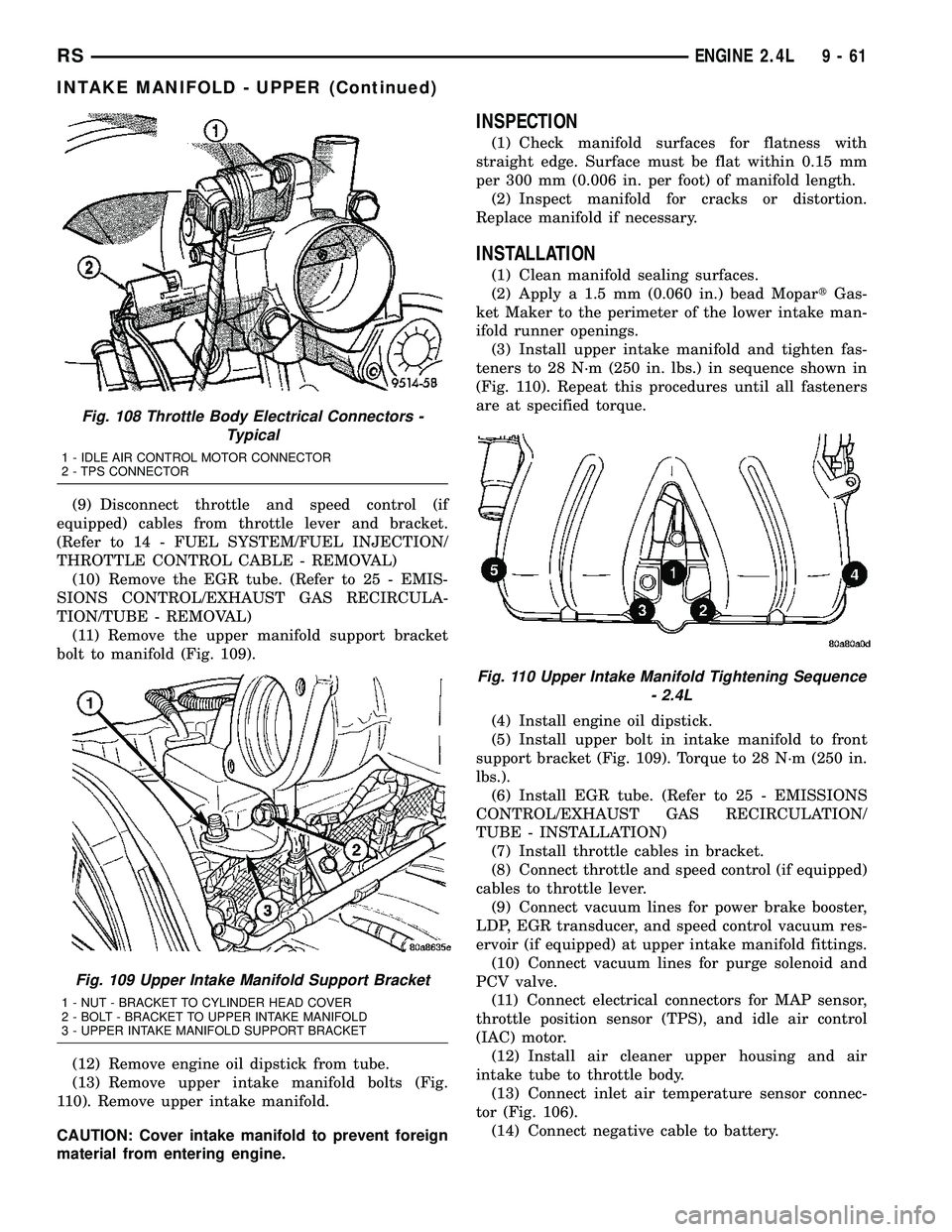
(11) Remove the upper manifold support bracket
bolt to manifold (Fig. 109).
(12) Remove engine oil dipstick from tube.
(13) Remove upper intake manifold bolts (Fig.
110). Remove upper intake manifold.
CAUTION: Cover intake manifold to prevent foreign
material from entering engine.
INSPECTION
(1) Check manifold surfaces for flatness with
straight edge. Surface must be flat within 0.15 mm
per 300 mm (0.006 in. per foot) of manifold length.
(2) Inspect manifold for cracks or distortion.
Replace manifold if necessary.
INSTALLATION
(1) Clean manifold sealing surfaces.
(2) Apply a 1.5 mm (0.060 in.) bead MopartGas-
ket Maker to the perimeter of the lower intake man-
ifold runner openings.
(3) Install upper intake manifold and tighten fas-
teners to 28 N´m (250 in. lbs.) in sequence shown in
(Fig. 110). Repeat this procedures until all fasteners
are at specified torque.
(4) Install engine oil dipstick.
(5) Install upper bolt in intake manifold to front
support bracket (Fig. 109). Torque to 28 N´m (250 in.
lbs.).
(6) Install EGR tube. (Refer to 25 - EMISSIONS
CONTROL/EXHAUST GAS RECIRCULATION/
TUBE - INSTALLATION)
(7) Install throttle cables in bracket.
(8) Connect throttle and speed control (if equipped)
cables to throttle lever.
(9) Connect vacuum lines for power brake booster,
LDP, EGR transducer, and speed control vacuum res-
ervoir (if equipped) at upper intake manifold fittings.
(10) Connect vacuum lines for purge solenoid and
PCV valve.
(11) Connect electrical connectors for MAP sensor,
throttle position sensor (TPS), and idle air control
(IAC) motor.
(12) Install air cleaner upper housing and air
intake tube to throttle body.
(13) Connect inlet air temperature sensor connec-
tor (Fig. 106).
(14) Connect negative cable to battery.
Fig. 108 Throttle Body Electrical Connectors -
Typical
1 - IDLE AIR CONTROL MOTOR CONNECTOR
2 - TPS CONNECTOR
Fig. 109 Upper Intake Manifold Support Bracket
1 - NUT - BRACKET TO CYLINDER HEAD COVER
2 - BOLT - BRACKET TO UPPER INTAKE MANIFOLD
3 - UPPER INTAKE MANIFOLD SUPPORT BRACKET
Fig. 110 Upper Intake Manifold Tightening Sequence
- 2.4L
RSENGINE 2.4L9-61
INTAKE MANIFOLD - UPPER (Continued)
Page 1240 of 2339

(8) Install the upper intake manifold. (Refer to 9 -
ENGINE/MANIFOLDS/INTAKE MANIFOLD -
INSTALLATION)
(9) Fill the cooling system. (Refer to 7 - COOLING
- STANDARD PROCEDURE)
EXHAUST MANIFOLD
REMOVAL
(1) Raise vehicle and disconnect exhaust pipe from
the exhaust manifold.
(2) Disconnect upstream oxygen sensor connector
at the rear of exhaust manifold.
(3) Remove the bolts attaching the manifold to the
cylinder head.
(4) Remove exhaust manifold.
(5) Inspect the manifold. (Refer to 9 - ENGINE/
MANIFOLDS/EXHAUST MANIFOLD - INSPEC-
TION)
CLEANING
(1) Discard gasket (if equipped) and clean all sur-
faces of manifold and cylinder head.
INSPECTION
(1) Inspect manifold gasket surfaces for flatness
with straight edge. Surface must be flat within 0.15
mm per 300 mm (0.006 in. per foot) of manifold
length.
(2) Inspect manifolds for cracks or distortion.
Replace manifold as necessary.
INSTALLATION
(1) Install exhaust manifold with a new gasket.
Tighten attaching nuts in the sequence shown in
(Fig. 113) to 19 N´m (170 in. lbs.).
(2) Attach exhaust pipe to exhaust manifold and
tighten fasteners to 37 N´m (27 ft. lbs.).
(3) Install and connect the oxygen sensor. (Refer to
14 - FUEL SYSTEM/FUEL INJECTION/O2 SENSOR
- COMPONENT LOCATION)
TIMING BELT COVER(S)
REMOVAL
FRONT COVER - UPPER
(1) Remove upper timing belt cover fasteners (Fig.
114) and remove cover.
FRONT COVER - LOWER
(1) Remove crankshaft vibration damper (Refer to
9 - ENGINE/ENGINE BLOCK/VIBRATION
DAMPER - REMOVAL).(2) Remove generator drive belt tensioner assem-
bly (Refer to 7 - COOLING/ACCESSORY DRIVE/
BELT TENSIONERS - REMOVAL).
(3) Remove timing belt front cover bolts (Fig. 114)
and remove covers.
Fig. 113 Exhaust Manifold Tightening Sequence
Fig. 114 Front Timing Belt Covers
1 - BOLTS - UPPER FRONT COVER 6 N´m (50 in. lbs.)
2 - BOLTS - LOWER FRONT COVER 6 N´m (50 in. lbs.)
RSENGINE 2.4L9-63
INTAKE MANIFOLD - LOWER (Continued)
Page 1244 of 2339
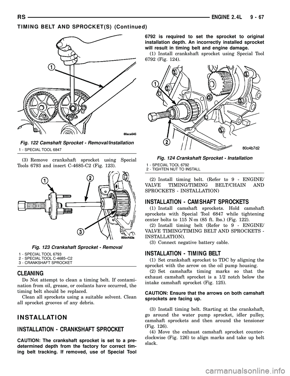
(3) Remove crankshaft sprocket using Special
Tools 6793 and insert C-4685-C2 (Fig. 123).
CLEANING
Do Not attempt to clean a timing belt. If contami-
nation from oil, grease, or coolants have occurred, the
timing belt should be replaced.
Clean all sprockets using a suitable solvent. Clean
all sprocket grooves of any debris.
INSTALLATION
INSTALLATION - CRANKSHAFT SPROCKET
CAUTION: The crankshaft sprocket is set to a pre-
determined depth from the factory for correct tim-
ing belt tracking. If removed, use of Special Tool6792 is required to set the sprocket to original
installation depth. An incorrectly installed sprocket
will result in timing belt and engine damage.
(1) Install crankshaft sprocket using Special Tool
6792 (Fig. 124).
(2) Install timing belt. (Refer to 9 - ENGINE/
VALVE TIMING/TIMING BELT/CHAIN AND
SPROCKETS - INSTALLATION)
INSTALLATION - CAMSHAFT SPROCKETS
(1) Install camshaft sprockets. Hold camshaft
sprockets with Special Tool 6847 while tightening
center bolts to 115 N´m (85 ft. lbs.) (Fig. 122).
(2) Install timing belt (Refer to 9 - ENGINE/
VALVE TIMING/TIMING BELT AND SPROCKETS -
INSTALLATION).
(3) Connect negative battery cable.
INSTALLATION - TIMING BELT
(1) Set crankshaft sprocket to TDC by aligning the
sprocket with the arrow on the oil pump housing.
(2) Set camshafts timing marks so that the
exhaust camshaft sprocket is a 1/2 notch below the
intake camshaft sprocket (Fig. 125).
CAUTION: Ensure that the arrows on both camshaft
sprockets are facing up.
(3) Install timing belt. Starting at the crankshaft,
go around the water pump sprocket, idler pulley,
camshaft sprockets and then around the tensioner
(Fig. 126).
(4) Move the exhaust camshaft sprocket counter-
clockwise (Fig. 126) to align marks and take up belt
slack.
Fig. 122 Camshaft Sprocket - Removal/Installation
1 - SPECIAL TOOL 6847
Fig. 123 Crankshaft Sprocket - Removal
1 - SPECIAL TOOL 6793
2 - SPECIAL TOOL C-4685±C2
3 - CRANKSHAFT SPROCKET
Fig. 124 Crankshaft Sprocket - Installation
1 - SPECIAL TOOL 6792
2 - TIGHTEN NUT TO INSTALL
RSENGINE 2.4L9-67
TIMING BELT AND SPROCKET(S) (Continued)
Page 1245 of 2339
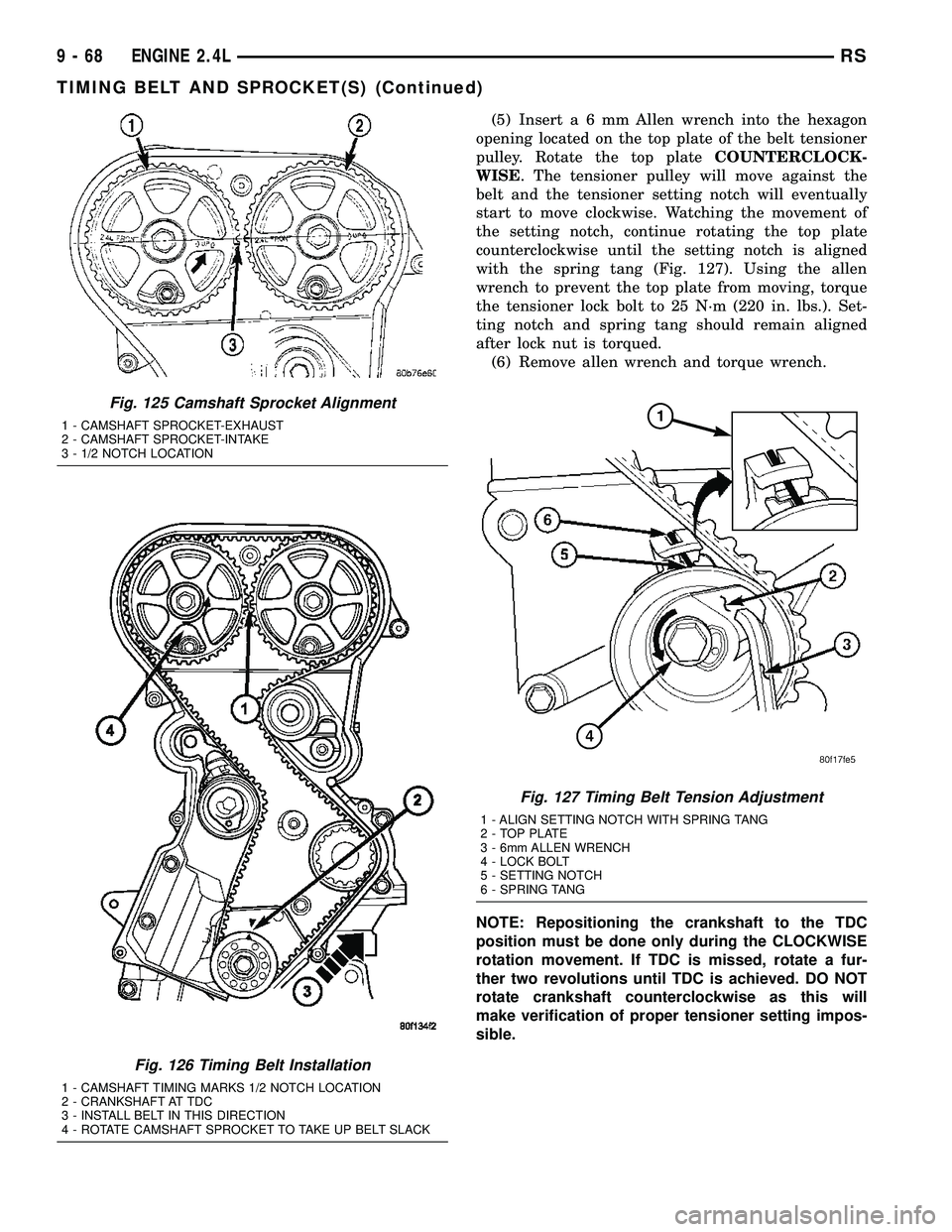
(5) Inserta6mmAllen wrench into the hexagon
opening located on the top plate of the belt tensioner
pulley. Rotate the top plateCOUNTERCLOCK-
WISE. The tensioner pulley will move against the
belt and the tensioner setting notch will eventually
start to move clockwise. Watching the movement of
the setting notch, continue rotating the top plate
counterclockwise until the setting notch is aligned
with the spring tang (Fig. 127). Using the allen
wrench to prevent the top plate from moving, torque
the tensioner lock bolt to 25 N´m (220 in. lbs.). Set-
ting notch and spring tang should remain aligned
after lock nut is torqued.
(6) Remove allen wrench and torque wrench.
NOTE: Repositioning the crankshaft to the TDC
position must be done only during the CLOCKWISE
rotation movement. If TDC is missed, rotate a fur-
ther two revolutions until TDC is achieved. DO NOT
rotate crankshaft counterclockwise as this will
make verification of proper tensioner setting impos-
sible.
Fig. 125 Camshaft Sprocket Alignment
1 - CAMSHAFT SPROCKET-EXHAUST
2 - CAMSHAFT SPROCKET-INTAKE
3 - 1/2 NOTCH LOCATION
Fig. 126 Timing Belt Installation
1 - CAMSHAFT TIMING MARKS 1/2 NOTCH LOCATION
2 - CRANKSHAFT AT TDC
3 - INSTALL BELT IN THIS DIRECTION
4 - ROTATE CAMSHAFT SPROCKET TO TAKE UP BELT SLACK
Fig. 127 Timing Belt Tension Adjustment
1 - ALIGN SETTING NOTCH WITH SPRING TANG
2 - TOP PLATE
3 - 6mm ALLEN WRENCH
4 - LOCK BOLT
5 - SETTING NOTCH
6 - SPRING TANG
9 - 68 ENGINE 2.4LRS
TIMING BELT AND SPROCKET(S) (Continued)
Page 1253 of 2339

ENGINE 3.3/3.8L
TABLE OF CONTENTS
page page
ENGINE 3.3/3.8L
DESCRIPTION.........................78
DIAGNOSIS AND TESTING
DIAGNOSIS AND TESTING - ENGINE
DIAGNOSIS - INTRODUCTION...........78
DIAGNOSIS AND TESTING - ENGINE
DIAGNOSIS - PERFORMANCE...........80
DIAGNOSIS AND TESTING - ENGINE
DIAGNOSIS - MECHANICAL.............82
DIAGNOSIS AND TESTING - ENGINE OIL
LEAK INSPECTION....................84
DIAGNOSIS AND TESTING - CYLINDER
COMPRESSION PRESSURE TEST........85
DIAGNOSIS AND TESTING - CYLINDER
COMBUSTION PRESSURE LEAKAGE
TEST...............................85
STANDARD PROCEDURE
STANDARD PROCEDURE - MEASURING
BEARING CLEARANCE USING
PLASTIGAGE........................86
FORM-IN-PLACE GASKETS AND SEALERS . 86
STANDARD PROCEDURE - ENGINE
GASKET SURFACE PREPARATION........87
HYDROSTATIC LOCKED ENGINE.........87
STANDARD PROCEDURE - REPAIR OF
DAMAGED OR WORN THREADS.........88
STANDARD PROCEDURE - ENGINE CORE
AND OIL GALLERY PLUGS..............88
REMOVAL - ENGINE ASSEMBLY...........88
INSTALLATION - ENGINE ASSEMBLY........91
SPECIFICATIONS
3.3/3.8L ENGINE......................93
SPECIFICATIONS - TORQUE............97
SPECIAL TOOLS
3.3/3.8L ENGINE......................98
AIR CLEANER ELEMENT
REMOVAL............................101
INSTALLATION........................101
AIR CLEANER HOUSING
REMOVAL............................101
INSTALLATION........................102
CYLINDER HEAD
DESCRIPTION........................102
DIAGNOSIS AND TESTINGÐCYLINDER HEAD
GASKET...........................102
REMOVAL - CYLINDER HEAD............103
CLEANING...........................103
INSPECTION.........................104
INSTALLATION - CYLINDER HEAD.........104CYLINDER HEAD COVER(S)
DESCRIPTION........................105
CYLINDER HEAD COVER - RIGHT
REMOVAL............................106
INSTALLATION........................106
CYLINDER HEAD COVER - LEFT
REMOVAL............................107
INSTALLATION........................107
INTAKE/EXHAUST VALVES & SEATS
DESCRIPTION........................107
OPERATION..........................107
STANDARD PROCEDURE - REFACING
VALVESANDVALVESEATS ............107
REMOVAL............................108
CLEANING...........................108
INSPECTION.........................108
INSTALLATION........................109
VALVE SPRINGS
DESCRIPTION........................109
OPERATION..........................109
REMOVAL
REMOVAL - CYLINDER HEAD OFF.......109
REMOVAL - CYLINDER HEAD ON........111
INSPECTION..........................111
INSTALLATION
INSTALLATION - CYLINDER HEAD OFF . . . 111
INSTALLATION - CYLINDER HEAD ON....111
ROCKER ARMS
DESCRIPTION
DESCRIPTION - ROCKER ARMS.........112
DESCRIPTION - PUSHRODS............112
OPERATION
OPERATION - ROCKER ARMS..........112
OPERATION - PUSHRODS.............112
REMOVAL - ROCKER ARMS AND SHAFT....112
DISASSEMBLY - ROCKER ARMS
AND SHAFT.........................113
ASSEMBLY - ROCKER ARMS AND SHAFT . . . 113
INSTALLATION - ROCKER ARMS
AND SHAFT.........................113
VALVE STEM SEALS
DESCRIPTION........................114
REMOVAL............................115
INSTALLATION........................115
ENGINE BLOCK
DESCRIPTION........................115
STANDARD PROCEDURE - CYLINDER BORE
HONING............................115
CLEANING...........................115
9 - 76 ENGINE 3.3/3.8LRS
Page 1255 of 2339

INSPECTION.........................145
ASSEMBLY...........................146
INSTALLATION........................146
INTAKE MANIFOLD
DESCRIPTION........................147
DIAGNOSIS AND TESTING - INTAKE
MANIFOLD LEAKS....................147
INTAKE MANIFOLD - UPPER
STANDARD PROCEDURE
STANDARD PROCEDURE - MANIFOLD
STRIPPED THREAD REPAIR............147
STANDARD PROCEDURE - INTAKE
MANIFOLD VACUUM PORT REPAIR......148
REMOVAL - UPPER INTAKE MANIFOLD.....148
CLEANING...........................148
INSPECTION.........................149
INSTALLATION - UPPER INTAKE MANIFOLD . 149
INTAKE MANIFOLD - LOWER
REMOVAL - LOWER INTAKE MANIFOLD....150
CLEANING...........................151
INSPECTION.........................151
INSTALLATION - LOWER INTAKE MANIFOLD . 151
EXHAUST MANIFOLD - RIGHT
REMOVAL............................152
CLEANING...........................153
INSPECTION.........................153INSTALLATION........................153
EXHAUST MANIFOLD - LEFT
REMOVAL............................154
CLEANING...........................154
INSPECTION.........................155
INSTALLATION........................155
VALVE TIMING
STANDARD PROCEDURE
STANDARD PROCEDURE - VALVE TIMING
VERIFICATION.......................155
STANDARD PROCEDURE - MEASURING
TIMING CHAIN WEAR.................155
TIMING CHAIN COVER
REMOVAL............................156
INSTALLATION........................157
TIMING CHAIN AND SPROCKETS
REMOVAL
REMOVAL - TIMING CHAIN AND
CAMSHAFT SPROCKET...............159
REMOVAL - CRANKSHAFT SPROCKET . . . 159
INSTALLATION
INSTALLATION - CRANKSHAFT
SPROCKET.........................160
INSTALLATION - TIMING CHAIN AND
CAMSHAFT SPROCKET...............160
ENGINE 3.3/3.8L
DESCRIPTION
The 3.3 Liter (201 cu. in.) and 3.8 Liter (231 cu.
in.) engines are 60É V-6 engines with cast iron cylin-
der blocks and aluminum cylinder heads (Fig. 1). The
engine uses a single, block mounted camshaft with
pushrods to actuate the valves. These engines do not
have provisions for a free wheeling valve train.
The firing order is 1±2±3±4±5±6. The cylinders are
numbered from the front of the engine to the rear.
The front cylinder bank is numbered 2, 4, and 6. The
rear cylinder bank is numbered 1, 3, and 5.
The engine identification number is located on the
rear of the cylinder block just below the cylinder
head (Fig. 2).
DIAGNOSIS AND TESTING
DIAGNOSIS AND TESTING - ENGINE
DIAGNOSIS - INTRODUCTION
Engine diagnosis is helpful in determining the
causes of malfunctions not detected and remedied by
routine maintenance.These malfunctions may be classified as either
mechanical (e.g., a strange noise), or performance
(e.g., engine idles rough and stalls).
Refer to the Engine Mechanical and the Engine
Performance diagnostic charts, for possible causes
and corrections of malfunctions (Refer to 9 - ENGINE
- DIAGNOSIS AND TESTING - MECHANICAL)
(Refer to 9 - ENGINE - DIAGNOSIS AND TESTING
- PERFORMANCE).
For fuel system diagnosis, (Refer to 14 - FUEL
SYSTEM/FUEL DELIVERY - DIAGNOSIS AND
TESTING).
Additional tests and diagnostic procedures may be
necessary for specific engine malfunctions that can-
not be isolated with the Service Diagnosis charts.
Information concerning additional tests and diagno-
sis is provided within the following:
²Cylinder Compression Pressure Test
²Cylinder Combustion Pressure Leakage Test
²Engine Cylinder Head Gasket Failure Diagnosis
²Intake Manifold Leakage Diagnosis
²Hydraulic Lash Adjuster Noise Diagnosis
²Engine Oil Leak Inspection
9 - 78 ENGINE 3.3/3.8LRS
Page 1258 of 2339

CONDITION POSSIBLE CAUSE CORRECTION
ENGINE LOSS OF POWER 1. Dirty or incorrectly gapped plugs. 1. Clean plugs and set gap.
2. Contamination in fuel system. 2. Clean system and replace fuel
filter.
3. Faulty fuel pump. 3. Test and replace as necessary.
(Refer to Appropriate Diagnostic
Information)
4. Incorrect valve timing. 4. Correct valve timing.
5. Leaking cylinder head gasket. 5. Replace cylinder head gasket.
6. Low compression. 6. Test compression of each
cylinder.
7. Burned, warped, or pitted valves. 7. Replace valves.
8. Plugged or restricted exhaust
system.8. Perform exhaust restriction test.
(Refer to 11 - EXHAUST SYSTEM -
DIAGNOSIS AND TESTING) Install
new parts, as necessary.
9. Faulty ignition coil(s). 9. Test and replace as necessary.
(Refer to Appropriate Diagnostic
Information)
ENGINE MISSES ON
ACCELERATION1. Dirty or incorrectly gapped spark
plugs.1. Clean spark plugs and set gap.
2. Contamination in Fuel System. 2. Clean fuel system and replace
fuel filter.
3. Burned, warped, or pitted valves. 3. Replace valves.
4. Faulty ignition coil(s). 4. Test and replace as necessary.
(Refer to Appropriate Diagnostic
Information)
ENGINE MISSES AT HIGH SPEED 1. Dirty or incorrect spark plug gap. 1. Clean spark plugs and set gap.
2. Faulty ignition coil(s). 2. Test and replace as necessary.
(Refer to Appropriate Diagnostic
Information)
3. Dirty fuel injector(s). 3. Test and replace as necessary.
(Refer to Appropriate Diagnostic
Information)
4. Contamination in fuel system. 4. Clean system and replace fuel
filter.
RSENGINE 3.3/3.8L9-81
ENGINE 3.3/3.8L (Continued)