exhaust CHRYSLER VOYAGER 2005 Repair Manual
[x] Cancel search | Manufacturer: CHRYSLER, Model Year: 2005, Model line: VOYAGER, Model: CHRYSLER VOYAGER 2005Pages: 2339, PDF Size: 59.69 MB
Page 1401 of 2339

INSTALLATION
INSTALLATION - 2.4L
(1) Install sensor.
(2) Install two screws and tighten.
(3) Connect the electrical connector and vacuum
hose to the MAP sensor (Fig. 20).
(4) Connect the negative battery cable.
INSTALLATION - 3.3/3.8L
(1) Install sensor (Fig. 21).
(2) Install screws and tighten toPLASTIC MAN-
IFOLD 1.7 N´m (15 in. lbs.) ALUMINUM MANI-
FOLD 3.3 N´m (30 in. lbs.).
(3) Connect the electrical connector to the sensor.
Install vacuum hose.
(4) Connect the negative battery cable.
O2 SENSOR
DESCRIPTION
The upstream oxygen sensor threads into the out-
let flange of the exhaust manifold (Fig. 22) or (Fig.
23).
The downstream heated oxygen sensor threads into
the outlet pipe at the rear of the catalytic convertor
(Fig. 24).
OPERATION
A seperate upstream and downstream grounds are
used on the NGC vehicles (4 Cyl.).
As vehicles accumulate mileage, the catalytic con-
vertor deteriorates. The deterioration results in a
less efficient catalyst. To monitor catalytic convertordeterioration, the fuel injection system uses two
heated oxygen sensors. One sensor upstream of the
catalytic convertor, one downstream of the convertor.
The PCM compares the reading from the sensors to
calculate the catalytic convertor oxygen storage
capacity and converter efficiency. Also, the PCM uses
the upstream heated oxygen sensor input when
adjusting injector pulse width.
When the catalytic converter efficiency drops below
emission standards, the PCM stores a diagnostic
trouble code and illuminates the malfunction indica-
tor lamp (MIL).
The O2 sensors produce a constant 2.5 volts on
NGC vehicles, depending upon the oxygen content of
the exhaust gas. When a large amount of oxygen is
Fig. 22 O2 SENSOR UPSTREAM 1/1 - 2.4L
Fig. 23 O2 SENSOR UPSTREAM 1/1 - 3.3/3.8L
Fig. 24 O2 SENSOR DOWNSTREAM 1/2 - 2.4/3.3/
3.8L
14 - 36 FUEL INJECTIONRS
MAP SENSOR (Continued)
Page 1402 of 2339

present (caused by a lean air/fuel mixture, can be
caused by misfire and exhaust leaks), the sensors
produces a low voltage. When there is a lesser
amount of oxygen present (caused by a rich air/fuel
mixture, can be caused by internal engine problems)
it produces a higher voltage. By monitoring the oxy-
gen content and converting it to electrical voltage,
the sensors act as a rich-lean switch.
The oxygen sensors are equipped with a heating
element that keeps the sensors at proper operating
temperature during all operating modes. Maintaining
correct sensor temperature at all times allows the
system to enter into closed loop operation sooner.
Also, it allows the system to remain in closed loop
operation during periods of extended idle.
In Closed Loop operation the PCM monitors the O2
sensors input (along with other inputs) and adjusts
the injector pulse width accordingly. During Open
Loop operation the PCM ignores the O2 sensor input.
The PCM adjusts injector pulse width based on pre-
programmed (fixed) values and inputs from other
sensors.
NGC Controller - Has a common ground for the
heater in the O2S. 12 volts is supplied to the heater
in the O2S by the NGC controller. Both the upstream
and downstream O2 sensors for NGC are pulse width
modulation (PWM).NOTE: When replacing an O2
Sensor, the PCM RAM memory must be cleared,
either by disconnecting the PCM C-1 connector or
momentarily disconnecting the Battery negative ter-
minal. The NGC learns the characteristics of each O2
heater element and these old values should be
cleared when installing a new O2 sensor. The cus-
tomer may experience driveability issues if this is not
performed.
UPSTREAM OXYGEN SENSOR
The input from the upstream heated oxygen sensor
tells the PCM the oxygen content of the exhaust gas.
Based on this input, the PCM fine tunes the air-fuel
ratio by adjusting injector pulse width.
The sensor input switches from 2.5 to 3.5 volt,
depending upon the oxygen content of the exhaust
gas in the exhaust manifold. When a large amount ofoxygen is present (caused by a lean air-fuel mixture),
the sensor produces voltage as low as 2.5 volt. When
there is a lesser amount of oxygen present (rich air-
fuel mixture) the sensor produces a voltage as high
as 3.5 volt. By monitoring the oxygen content and
converting it to electrical voltage, the sensor acts as
a rich-lean switch.
The heating element in the sensor provides heat to
the sensor ceramic element. Heating the sensor
allows the system to enter into closed loop operation
sooner. Also, it allows the system to remain in closed
loop operation during periods of extended idle.
In Closed Loop, the PCM adjusts injector pulse
width based on the upstream heated oxygen sensor
input along with other inputs. In Open Loop, the
PCM adjusts injector pulse width based on prepro-
grammed (fixed) values and inputs from other sen-
sors.
DOWNSTREAM OXYGEN SENSOR
The downstream heated oxygen sensor input is
used to detect catalytic convertor deterioration. As
the convertor deteriorates, the input from the down-
stream sensor begins to match the upstream sensor
input except for a slight time delay. By comparing
the downstream heated oxygen sensor input to the
input from the upstream sensor, the PCM calculates
catalytic convertor efficiency. Also used to establish
the upstream O2 goal voltage (switching point).
REMOVAL
REMOVAL - UPSTREAM 1/1 - 2.4L
(1) Disconnect the negative battery cable.
(2) Raise and support the vehicle.
(3) Disconnect the electrical connector (Fig. 23).
(4) Use a socket such as the Snap-OntYA8875 or
equivalent to remove the sensor
(5) When the sensor is removed, the threads must
be cleaned with an 18 mm X 1.5 + 6E tap. If using
the original sensor, coat the threads with Loctite
771±64 anti-seize compound or equivalent.
RSFUEL INJECTION14-37
O2 SENSOR (Continued)
Page 1403 of 2339

REMOVAL - UPSTREAM 1/1 - 3.3/3.8L
(1) Remove battery, refer to the Battery section for
more information.
(2) Remove the battery tray, refer to the Battery
section for more information.
(3) Disconnect the speed control vacuum harness
from servo.
(4) Disconnect the electrical connector from servo.
(5) Remove the speed control servo and bracket
and reposition.
(6) Use a socket such as the Snap-OntYA8875 or
equivalent to remove the sensor (Fig. 25).
(7) When the sensor is removed, the threads must
be cleaned with an 18 mm X 1.5 + 6E tap. If using
the original sensor, coat the threads with Loctite
771±64 anti-seize compound or equivalent.
REMOVAL - DOWNSTREAM 1/2 - 2.4/3.3/3.8L
(1) Disconnect the negative battery cable.
(2) Raise and support the vehicle.
(3) Disconnect the electrical connector (Fig. 26).
(4) Use a socket such as the Snap-OntYA8875 or
equivalent to remove the sensor (Fig. 27).
(5) When the sensor is removed, the threads must
be cleaned with an 18 mm X 1.5 + 6E tap. If using
the original sensor, coat the threads with Loctite
771±64 anti-seize compound or equivalent.
INSTALLATION
INSTALLATION - UPSTREAM 1/1 - 2.4L
The engines uses two heated oxygen sensors.
(1) After removing the sensor, the exhaust mani-
fold threads must be cleaned with an 18 mm X 1.5 +
6E tap. If reusing the original sensor, coat the sensor
threads with an anti-seize compound such as Loctite
771- 64 or equivalent. New sensors have compound
on the threads and do not require an additional coat-
ing.
Fig. 25 O2 SENSOR 1/1
Fig. 26 Downstream Oxygen Sensor (1/2)
1 - OXYGEN SENSOR CONNECTOR
2 - CATALYTIC CONVERTER
3 - DOWNSTREAM OXYGEN SENSOR
4 - ENGINE HARNESS CONNECTOR
Fig. 27 DOWNSTREAM 2/1 O2 SENSOR
14 - 38 FUEL INJECTIONRS
O2 SENSOR (Continued)
Page 1404 of 2339

(2) Install sensor and tighten to 27 N´m (20 ft.
lbs.) (Fig. 23).
(3) Connect the electrical connector for the O2 sen-
sor and install onto bracket.
(4) Lower vehicle.
(5) Connect the negative battery cable.
INSTALLATION - UPSTREAM 1/1 - 3.3/3.8L
The engines uses two heated oxygen sensors.
(1) After removing the sensor, the exhaust mani-
fold threads must be cleaned with an 18 mm X 1.5 +
6E tap. If reusing the original sensor, coat the sensor
threads with an anti-seize compound such as Loctite
771- 64 or equivalent. New sensors have compound
on the threads and do not require an additional coat-
ing.
(2) Install sensor and tighten to 27 N´m (20 ft.
lbs.).
(3) Connect the electrical connector for the O2 sen-
sor and install onto bracket.
(4) Connect the electrical connector for the speed
control servo.
(5) Install the speed control servo and bracket
refer to the Speed Control Servo for more informa-
tion.
(6) Connect the speed control vacuum harness to
servo.
(7) Install the battery tray, refer to the Battery
section for more information.
(8) Install battery, refer to the Battery section for
more information.
INSTALLATION DOWNSTREAM 2/1 -
2.4/3.3/3.8L
The O2S is located on the side of the catalytic con-
verter.
Threads of new oxygen sensors are factory coated
with anti-seize compound to aid in removal.DO
NOT add any additional anti-seize compound to
the threads of a new oxygen sensor.
(1) Install sensor and tighten to 27 N´m (20 ft.
lbs.).
(2) Connect the electrical connector.
(3) Lower vehicle.
(4) Install the negative battery cable.
THROTTLE BODY
DESCRIPTION
The throttle body is located on the intake manifold
(Fig. 28) or (Fig. 29). Fuel does not enter the intake
manifold through the throttle body. Fuel is sprayed
into the manifold by the fuel injectors.
OPERATION
Filtered air from the air cleaner enters the intake
manifold through the throttle body. The throttle body
contains an air control passage controlled by an Idle
Air Control (IAC) motor. The air control passage is
used to supply air for idle conditions. A throttle valve
(plate) is used to supply air for above idle conditions.
Certain sensors are attached to the throttle body.
The accelerator pedal cable, speed control cable are
connected to the throttle body cam.
Fig. 28 IAC VALVE 2.4L
1 - Idle Air Control Valve
2 - Throttle Position Sensor
Fig. 29 IAC VALVE LOCATION 3.3/3.8L
1 - Idle Air Control Valve
2 - Throttle Position Sensor
RSFUEL INJECTION14-39
O2 SENSOR (Continued)
Page 1433 of 2339

GEAR
TABLE OF CONTENTS
page page
GEAR
DESCRIPTION.........................26
OPERATION...........................26
WARNING
WARNINGS AND CAUTIONS.............26
REMOVAL
REMOVAL - LHD GEAR.................26
REMOVAL - RHD GEAR................29INSTALLATION
INSTALLATION - LHD GEAR.............31
INSTALLATION - RHD GEAR.............33
SPECIAL TOOLS
POWER STEERING GEAR..............34
OUTER TIE ROD
REMOVAL.............................34
INSTALLATION.........................35
GEAR
DESCRIPTION
This vehicle is equipped with a rack and pinion
power steering gear (Fig. 1). It is mounted to the
underside of the front suspension cradle/crossmem-
ber.
The steering column is attached to the gear
through the use of an intermediate shaft and cou-
plers. The outer ends of the power steering gear's
outer tie rods connect to the steering knuckles.
NOTE: The power steering gear should NOT be ser-
viced or adjusted unless DaimlerChrysler Corpora-
tion authorizes. If a malfunction or oil leak occurs,
the complete steering gear should be replaced.
Only the outer tie rods may be replaced separately
from the rest of the gear.
OPERATION
Turning of the steering wheel is converted into lin-
ear (side-to-side) travel through the meshing of the
helical pinion teeth with the rack teeth in the steer-
ing gear. This travel pushes and pulls the tie rods to
change the direction of the vehicle's front wheels.
Power assist steering provided by the power steer-
ing pump is controlled by an open center, rotary type
control valve which directs oil from the pump to
either side of the integral rack piston upon demand.
Road feel is controlled by the diameter of a torsion
bar which initially steers the vehicle. As required
steering effort increases, as in a turn, the torsion bar
twists, causing relative rotary motion between the
rotary valve body and the valve spool. This move-
ment directs oil behind the integral rack piston
which, in turn, builds hydraulic pressure and assists
in the turning effort.Manual steering control of the vehicle can be main-
tained if power steering assist is lost. However,
under this condition, steering effort is significantly
increased.
WARNING
WARNINGS AND CAUTIONS
WARNING: POWER STEERING FLUID, ENGINE
PARTS AND EXHAUST SYSTEM MAY BE
EXTREMELY HOT IF ENGINE HAS BEEN RUNNING.
DO NOT START ENGINE WITH ANY LOOSE OR DIS-
CONNECTED HOSES. DO NOT ALLOW HOSES TO
TOUCH HOT EXHAUST MANIFOLD OR CATALYST.
WARNING: FLUID LEVEL SHOULD BE CHECKED
WITH THE ENGINE OFF TO PREVENT PERSONAL
INJURY FROM MOVING PARTS.
CAUTION: When the system is open, cap all open
ends of the hoses, power steering pump fittings or
power steering gear ports to prevent entry of for-
eign material into the components.
REMOVAL
REMOVAL - LHD GEAR
(1) Remove cap from power steering fluid reser-
voir.
(2) Using a siphon pump, remove as much fluid as
possible from the power steering fluid reservoir.Use
care not to damage the filter mesh below the
fluid surface.
19 - 26 GEARRS
Page 1444 of 2339

DESCRIPTION - PUMP (DIESEL)
Hydraulic pressure for the operation of the power
steering gear is provided by a belt driven power
steering pump. The power steering pump is mounted
front lower right corner of the engine (Fig. 13).
The pump has a supply fitting for fluid coming
from the reservoir and a pressure port for exiting
fluid that is headed for the steering gear.
OPERATION
The power steering pump is a constant displace-
ment vane type pump. The 2.4L pump has an inte-
gral fluid reservoir and there is a secondary remote
non-flow reservoir which acts only as a fluid fill and
check point. The 3.3L/3.8L pump houses very little
fluid and is therefore supplied by a remote flow
through reservoir.
WARNING
WARNING: POWER STEERING FLUID, ENGINE
PARTS AND EXHAUST SYSTEM MAY BE
EXTREMELY HOT IF ENGINE HAS BEEN RUNNING.
DO NOT START ENGINE WITH ANY LOOSE OR DIS-
CONNECTED HOSES. DO NOT ALLOW HOSES TO
TOUCH HOT EXHAUST MANIFOLD OR CATALYST.
WARNING: FLUID LEVEL SHOULD BE CHECKED
WITH THE ENGINE OFF TO PREVENT PERSONAL
INJURY FROM MOVING PARTS.
CAUTION
CAUTION: When the system is open, cap all open
ends of the hoses, power steering pump fittings or
power steering gear ports to prevent entry of for-
eign material into the components.
STANDARD PROCEDURE - POWER STEERING
PUMP INITIAL OPERATION
WARNING: FLUID LEVEL SHOULD BE CHECKED
AND ADJUSTED WITH ENGINE OFF TO PREVENT
INJURY FROM MOVING ENGINE COMPONENTS.
CAUTION: Use only MoparTAutomatic Transmis-
sion Fluid (MS-9602) in power steering system. Use
of other MoparTpower steering fluids (MS5931 and
MS9933) should be avoided to ensure peak perfor-
mance of the power steering system under all oper-
ating conditions. Do not overfill.
Fig. 1 POWER STEERING PUMP (2.4L)
1 - PULLEY
2 - BRACKET
3 - PRESSURE FITTING
4 - RETURN FITTING
5 - SUPPLY FITTING
Fig. 2 POWER STEERING PUMP (3.3L/3.8L)
1 - SUPPLY FITTING
2 - PRESSURE FITTING
3 - PULLEY
RSPUMP19-37
PUMP (Continued)
Page 1445 of 2339
Read the fluid level through the side of the power
steering fluid reservoir. The fluid level should indi-
cateªFILL RANGEºwhen the fluid is at a temper-
ature of approximately 21ÉC to 27ÉC (70ÉF to 80ÉF).
(1) Wipe the filler cap and area clean, then remove
the cap.
(2) Fill the fluid reservoir to the proper level and
let the fluid settle for at least two (2) minutes.
(3) Start the engine and let run for a few seconds,
then turn the engine off.
(4) Add fluid if necessary. Repeat the above steps
until the fluid level remains constant after running
the engine.
(5) Raise the front wheels off the ground.
(6) Start the engine.
(7) Slowly turn the steering wheel right and left,
lightly contacting the wheel stops.
(8) Add fluid if necessary.
(9) Lower the vehicle, then turn the steering wheel
slowly from lock-to-lock.
(10) Stop the engine. Check the fluid level and
refill as required.
(11) If the fluid is extremely foamy, allow the vehi-
cle to stabilize a few minutes, then repeat the above
procedure.
REMOVAL
REMOVAL - PUMP (2.4L ENGINE)
(1) Remove the (-) negative battery cable from the
battery and isolate cable.
(2) Remove the cap from the power steering fluid
reservoir.
(3) Using a siphon pump, remove as much power
steering fluid as possible from the power steering
fluid reservoir.
(4) Raise the vehicle on jack stands or centered on
a frame contact type hoist. See Hoisting in Lubrica-
tion and Maintenance.
(5) Disconnect the oxygen sensor wiring harness
from the vehicle wiring harness at the rear engine
mount bracket.
NOTE: The exhaust system needs to be removed
from the engine to allow for an area to remove the
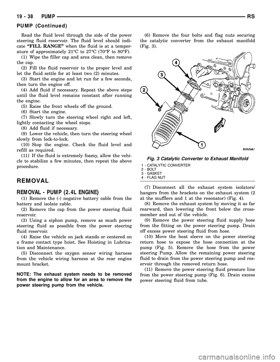
power steering pump from the vehicle.(6) Remove the four bolts and flag nuts securing
the catalytic converter from the exhaust manifold
(Fig. 3).
(7) Disconnect all the exhaust system isolators/
hangers from the brackets on the exhaust system (2
at the mufflers and 1 at the resonator) (Fig. 4).
(8) Remove the exhaust system by moving it as far
rearward, then lowering the front below the cross-
member and out of the vehicle.
(9) Remove the power steering fluid supply hose
from the fitting on the power steering pump. Drain
off excess power steering fluid from hose.
(10) Move the heat sleeve on the power steering
return hose to expose the hose connection at the
pump (Fig. 5). Remove the hose from the power
steering Pump. Allow the remaining power steering
fluid to drain from the power steering pump and res-
ervoir through the removed return hose.
(11) Remove the power steering fluid pressure line
from the power steering pump (Fig. 6). Drain excess
power steering fluid from tube.
Fig. 3 Catalytic Converter to Exhaust Manifold
1 - CATALYTIC CONVERTER
2 - BOLT
3 - GASKET
4 - FLAG NUT
19 - 38 PUMPRS
PUMP (Continued)
Page 1446 of 2339

Fig. 4 Exhaust System - Typical (All Vehicles)
1 - CATALYTIC CONVERTER 4 - SUPPORT - RESONATOR
2 - BAND CLAMP 5 - RESONATOR
3 - SUPPORTS - MUFFLER 6 - MUFFLER
Fig. 5 Pressure And Return Hoses - 2.4L
1 - POWER STEERING PUMP
2 - RETURN HOSE (HEAT SLEEVE COVERED)
3 - ROUTING CLAMPS
4 - PRESSURE HOSE TUBE NUT
5 - RETURN HOSE TUBE NUT
6 - CRADLE CROSSMEMBER
7 - POWER STEERING GEAR
8 - PRESSURE HOSE
Fig. 6 Power Steering Fluid Pressure And Return
Hose
1 - POWER STEERING FLUID RETURN HOSE
2 - POWER STEERING PUMP
3 - POWER STEERING FLUID PRESSURE HOSE
RSPUMP19-39
PUMP (Continued)
Page 1447 of 2339

(12) Remove the fasteners, then the accessory
drive splash shield.
(13) Remove the adjuster nut attaching rear of
power steering pump to the cast mounting bracket.
(Fig. 7)
(14) Remove the front adjuster nut and the lower
pivot bolt (Fig. 8) attaching power steering pump
bracket to cast bracket.
(15) Remove the drive belt from the power steering
pump pulley.
(16) Remove the power steering pump and the
front bracket from the cast bracket on the engine as
an assembly through the exhaust tunnel.(17) Remove the 3 bolts attaching the front
bracket to the power steering pump and separate the
power steering pump from the front bracket.
(18) If the power steering pump pulley needs to be
transferred, (Refer to 19 - STEERING/PUMP - DIS-
ASSEMBLY).
REMOVAL - PUMP (3.3L/3.8L ENGINE)
(1) Remove the (-) negative battery cable from the
battery and isolate cable.
(2) Remove the wiper module (unit)(Refer to 8 -
ELECTRICAL/WIPERS/WASHERS/WIPER MOD-
ULE - REMOVAL).
(3) Raise the vehicle. (Refer to LUBRICATION &
MAINTENANCE/HOISTING - STANDARD PROCE-
DURE)
(4) Remove the drive belt splash shield.
(5) Remove the pressure hose routing bracket bolt
(Fig. 9).
(6) lower the vehicle.
(7) Remove cap from power steering fluid reser-
voir.
(8) Using a siphon pump, remove as much power
steering fluid as possible from the power steering
fluid reservoir.
(9) Disconnect the pressure hose from the pump
(Fig. 10).
(10) Disconnect the fluid supply hose from the
pump (Fig. 10).
Fig. 7 Power Steering Pump Attaching Nut
1 - POWER STEERING PUMP MOUNTING BRACKET
2 - FRONT SUSPENSION CRADLE
3 - POWER STEERING PUMP
4 - ADJUSTER NUT
Fig. 8 Pump Front Mounting
1 - ADJUSTER NUT
2 - PIVOT BOLT
3 - PUMP
Fig. 9 Pressure Hose Routing Clamp
1 - PRESSURE HOSE TUBE
2 - STEERING GEAR
3 - CRADLE CROSSMEMBER
4 - DRIVESHAFT
5 - ROUTING CLAMP BRACKET
19 - 40 PUMPRS
PUMP (Continued)
Page 1450 of 2339

INSTALLATION
INSTALLATION - PUMP (2.4L ENGINE)
(1) Install power steering pump back in vehicle
using the reverse order of its removal through the
exhaust tunnel of the vehicle.
(2) Install the power steering pump on its cast
mounting bracket (Fig. 7), then install the nut and
bolt attaching the front bracket to the cast bracket
(Fig. 8).Do not fully tighten at this time..
(3) Install the rear nut (Fig. 7).
(4) Install the power steering pump drive belt on
pulley and adjust (Refer to 7 - COOLING/ACCES-
SORY DRIVE/DRIVE BELTS - INSTALLATION).
(5) Tighten the two adjustment slot bolts and the
one pivot bolt to 54 N´m (40 ft. lbs.) torque.
(6) Install the accessory drive splash shield.
NOTE: Before installing power steering fluid pres-
sure hose on power steering pump, inspect the
O-ring on the pressure hose for damage and
replace if necessary.
(7) Install the power steering fluid pressure line
onto the output fitting of the power steering pump
(Fig. 6). Tighten the pressure line to pump fitting
tube nut to a torque of 31 N´m (275 in. lbs.).
(8) Install the power steering fluid low pressure
return hose on the power steering pump low pressure
fitting (Fig. 6).Be sure hose clamps are properly
reinstalled.
(9) Install the power steering fluid supply hose on
the power steering pump fluid fitting.Be sure hose
is clear of accessory drive belts all hose clamps
are properly reinstalled.
CAUTION: Heat sleeve must cover entire rubber
portion of return hose to ensure desired thermal
protection from exhaust.
(10) Properly position the protective heat sleeve
over the power steering return hose. Securely tie
strap the heat sleeve to the power steering hose to
keep in it's proper position.
(11)
Install the exhaust system (Fig. 4). Install all
exhaust system isolators/hangers on the exhaust sys-
tem brackets, then the four bolts and flag nuts (Fig. 3).
(12) Connect the oxygen sensor wiring harness to
the vehicle wiring harness.
(13) Lower vehicle.
(14) Connect the negative battery cable on the
negative battery post.
(15) Perform the POWER STEERING PUMP INI-
TIAL OPERATION procedure to properly fill and
bleed the power steering system. (Refer to 19 -
STEERING/PUMP - STANDARD PROCEDURE)
(16) Inspect for leaks.
INSTALLATION - PUMP (3.3L/3.8L ENGINE)
(1) Install power steering pump back in vehicle
using the reverse order of its removal through the
engine compartment of the vehicle.
(2) Install the power steering pump on its mount-
ing bracket.
(3) Install the 3 front power steering pump mount-
ing bolts (Fig. 11). Tighten the 3 front power steering
pump mounting bolts to a torque of 54 N´m (40 ft.
lbs.).
NOTE: Before installing power steering pressure
hose on power steering pump, inspect the O-ring
on the power steering pressure hose for damage
and replace if required.
(4) Install the power steering fluid pressure line
into the pressure output fitting of the power steering
pump (Fig. 10).Do not fully tighten tube nut at
this time.
(5) Install the power steering fluid supply hose on
the power steering pump supply fitting (Fig. 10).Be
sure hose clamp is properly installed.
(6) Raise the vehicle.
(7) Install the routing clip on the engine for the
pressure hose (Fig. 9) and tighten fastener.
(8) Install the serpentine drive belt (Refer to 7 -
COOLING/ACCESSORY DRIVE/DRIVE BELTS -
INSTALLATION).
(9) Install the drive belt splash shield.
(10) Lower the vehicle.
(11) Tighten the pressure line to pump pressure
fitting tube nut to a torque of 31 N´m (275 in. lbs.).
(12) Install the wiper module (unit)(Refer to 8 -
ELECTRICAL/WIPERS/WASHERS/WIPER MOD-
ULE - INSTALLATION).
(13) Connect the negative battery cable on the
negative battery post.
(14) Fill and bleed the power steering system
using the Power Steering Pump Initial Operation
Procedure (Refer to 19 - STEERING/PUMP - STAN-
DARD PROCEDURE).
(15) Inspect for leaks.
INSTALLATION - PUMP (DIESEL)
(1) Install the power steering pump on its cast
mounting bracket.
(2) Install the three front power steering pump
mounting bolts. Tighten the mounting bolts to a
torque of 54 N´m (40 ft. lbs.).
(3) Install the rear mounting bolt fastening the
stamped bracket to the cast bracket (Fig. 13).
Tighten the mounting bolt to a torque of 54 N´m (40
ft. lbs.).
RSPUMP19-43
PUMP (Continued)