Module CHRYSLER VOYAGER 2005 Service Manual
[x] Cancel search | Manufacturer: CHRYSLER, Model Year: 2005, Model line: VOYAGER, Model: CHRYSLER VOYAGER 2005Pages: 2339, PDF Size: 59.69 MB
Page 1752 of 2339

ASSEMBLY
NOTE: If valve body assembly is reconditioned, the
PCM/TCM Quick Learn Procedure must be per-
formed. (Refer to 8 - ELECTRICAL/ELECTRONIC
CONTROL MODULES/TRANSMISSION CONTROL
MODULE - STANDARD PROCEDURE)
(1) Install valves and springs as shown in (Fig.
356).
(2) Install regulator valve spring retainer (Fig.
357).
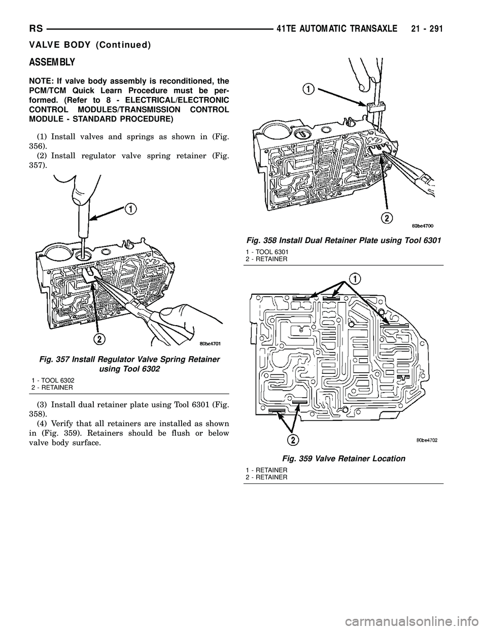
(3) Install dual retainer plate using Tool 6301 (Fig.
358).
(4) Verify that all retainers are installed as shown
in (Fig. 359). Retainers should be flush or below
valve body surface.
Fig. 357 Install Regulator Valve Spring Retainer
using Tool 6302
1 - TOOL 6302
2 - RETAINER
Fig. 358 Install Dual Retainer Plate using Tool 6301
1 - TOOL 6301
2 - RETAINER
Fig. 359 Valve Retainer Location
1 - RETAINER
2 - RETAINER
RS41TE AUTOMATIC TRANSAXLE21 - 291
VALVE BODY (Continued)
Page 1756 of 2339

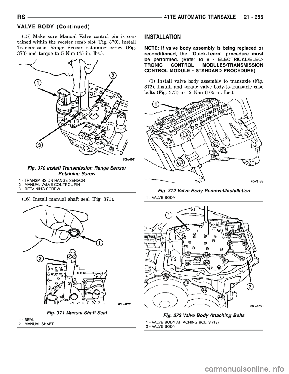
(15) Make sure Manual Valve control pin is con-
tained within the rooster comb slot (Fig. 370). Install
Transmission Range Sensor retaining screw (Fig.
370) and torque to 5 N´m (45 in. lbs.).
(16) Install manual shaft seal (Fig. 371).INSTALLATION
NOTE: If valve body assembly is being replaced or
reconditioned, the ªQuick-Learnº procedure must
be performed. (Refer to 8 - ELECTRICAL/ELEC-
TRONIC CONTROL MODULES/TRANSMISSION
CONTROL MODULE - STANDARD PROCEDURE)
(1) Install valve body assembly to transaxle (Fig.
372). Install and torque valve body-to-transaxle case
bolts (Fig. 373) to 12 N´m (105 in. lbs.).
Fig. 370 Install Transmission Range Sensor
Retaining Screw
1 - TRANSMISSION RANGE SENSOR
2 - MANUAL VALVE CONTROL PIN
3 - RETAINING SCREW
Fig. 371 Manual Shaft Seal
1 - SEAL
2 - MANUAL SHAFT
Fig. 372 Valve Body Removal/Installation
1 - VALVE BODY
Fig. 373 Valve Body Attaching Bolts
1 - VALVE BODY ATTACHING BOLTS (18)
2 - VALVE BODY
RS41TE AUTOMATIC TRANSAXLE21 - 295
VALVE BODY (Continued)
Page 1767 of 2339

OPERATION
The Tire Pressure Monitoring (TPM) system uses
radio and sensor technology to monitor tire air pres-
sure levels. Sensors, mounted to each road wheel as
part of the valve stem, transmit a low frequency indi-
cating their individual pressure to a receiver located
in the Wireless Control Module (WCM) portion of the
Sentry Key Remote Electronic Entry Module
(SKREEM). These transmissions occur approximately
once every minute at speeds over 20 mph (32 km/h).
The Tire Pressure Monitoring system remains active
even if no tire pressure related message is displayed.
The sensors lay dormant (Park Mode), then wake
and start transmitting (Drive Mode) when the vehicle
first reaches speeds over 20 mph (32 km/h). Once the
wheels stop rotating for a period of approximately 30
minutes, the sensors shut down until again awaken.
Although not transmitting as when in Drive Mode,
while in Park Mode, the sensors still transmit
approximately once every 13 hours to let the receiver
know air pressure status at that time.
The receiver only receives information from the
four rotating tires. A fifth sensor may be located in
the spare tire wheel, depending on vehicle options.
Although this fifth sensor may be present, it does not
broadcast any information because it does not rotate.
When the system detects that a tire is going low,
below the Low Pressure (lamp) ON Threshold (See
following table), the driver is alerted to the situation.
The Base system illuminates an indicator lamp,
warning the driver of a pressure issue and sounds an
audible chime. In equipped with the Premium sys-
tem, the information is also displayed on the Elec-
tronic Vehicle Information Center (EVIC).
Once pressure in the suspect tire raises above the
Low Pressure (lamp) OFF Threshold, the lamp will
go out and the system returns to normal.
TPM THRESHOLD PRESSURES
DESCRIPTION SPECIFICATION
Placard Pressure (Cold) 36 PSI (248 kPa)
Low Pressure OFF Threshold 33 PSI (228 kPa)
Low Pressure ON Threshold 28 PSI (193 kPa)
SENSOR - TPM
DESCRIPTION
On vehicles equipped with Tire Pressure Monitor-
ing, one tire pressure sensor is mounted to each road
wheel (Fig. 18), and depending on factory wheel
options, a sensor may be located in the spare tire
wheel. Both aluminum and steel wheels are used in
this system, although sensors for one type wheel can-
not be used in the other type wheel.Each sensor has an internal battery that lasts up
to 10 years. The battery is not serviceable. At the
time of battery failure, the sensor must be replaced.
The serviceable components of the tire pressure sen-
sor are:
²Sensor-To-Wheel Grommet
²Valve Stem Cap
²Valve Stem Core
Valve stem caps and cores are specifically designed
for the tire pressure monitoring sensors. Although
similar to standard valve stem caps and cores, they
are different.
CAUTION: Do not use a standard valve stem cap or
core in a tire pressure sensor. Always use the orig-
inal equipment style sensor cap and core.
CAUTION: Do not reuse the Sensor-To-Wheel Grom-
met. Always use a new grommet when installing a
pressure sensor and properly torque the sensor
nut.
CAUTION: Do not attempt to install a tire pressure
sensor in an aftermarket wheel. Use only in original
style factory wheels.
OPERATION
The battery operated tire pressure sensors lay dor-
mant (Park Mode), then wake and start transmitting
(Drive Mode) when the vehicle first reaches speeds
over 20 mph (32 km/h). Once the wheels stop rotat-
ing for a period of approximately 30 minutes, the
sensors shut down until again awaken. Although not
transmitting as when in Drive Mode, while in Park
Mode, the sensors still transmit approximately once
every 13 hours to let the receiver know air pressure
status at that time.
Each sensor transmits tire pressure data approxi-
mately once every minute. Each sensor's (transmit-
ter) broadcast is uniquely coded so that the wireless
control module (WCM) can monitor the state of each
of the sensors on the four rotating road wheels. The
WCM (located in the SKREEM) automatically learns
and stores the sensor's ID while driving after a sen-
sor has been replaced. There is no retraining neces-
sary.
The receiver only receives information from the
four rotating tires. A fifth sensor may be located in
the spare tire wheel, depending on vehicle options.
Although this fifth sensor may be present, it does not
broadcast any information because it does not rotate.
For additional information, refer to Appropriate
Diagnostic Information.
22 - 10 TIRES/WHEELSRS
TIRE PRESSURE MONITORING (Continued)
Page 1789 of 2339

(a) If the heat staked or component seam loca-
tion is loose, hold the two components tightly
together and using a soldering gun with a flat tip,
melt the material securing the components
together. Do not over heat the affected area, dam-
age to the exterior of the trim panel may occur.
(b) If the heat staked material is broken or miss-
ing, use a hot glue gun to apply new material to
the area to be repaired. The panels that are being
heat staked must be held together while the apply-ing the glue. Once the new material is in place, it
may be necessary to use a soldering gun to melt
the newly applied material. Do not over heat the
affected area, damage to the exterior of the trim
panel may occur.
(4) Allow the repaired area to cool and verify the
repair.
(5) Install trim panel.
SPECIFICATIONS
TORQUE
TORQUE SPECIFICATIONS
DESCRIPTION N´m Ft. Lbs. In. Lbs.
All seat belt anchor bolts 39 29 Ð
Armrest shoulder bolt 29 21 Ð
Bench seat riser bolts 48 35 Ð
Bench seat track nuts 48 35 Ð
Quad bucket seat track to cushion frame bolts 40 30 Ð
Bucket seat back pivot bolts 33 24 Ð
Center seat to seat track bolts 24 17 Ð
Child seat module screws (bench seats) 7 Ð 62
Child seat module screws (quad seats) 13.5 10 Ð
Crossmember to radiator closure panel bolts 28 21 Ð
Door check strap to door end frame 12 Ð 105
Door latch to door end frame bolts 10 Ð 89
Floor latch to seat cushion frame bolts 27 19 Ð
Fig. 14 COVER GAPS WITH MESH
1 - GROUND DOWN AREA
2 - PATCH
3 - MESH
Fig. 15 COVER MESH WITH ADHESIVE
1 - ADHESIVE
2 - MESH
3 - PATCH
4 - SPREADER
23 - 10 BODYRS
BODY (Continued)
Page 1829 of 2339

COWL GRILLE
REMOVAL
(1) Remove wiper arms. (Refer to 8 - ELECTRI-
CAL/WIPERS/WASHERS/WIPER ARMS -
REMOVAL)
(2) Remove four (4) screws securing cowl cover to
wiper module (Fig. 6).
(3) Disengage quarter turn fasteners at outboard
ends of cowl grill from body.
(4) Release hood latch and open hood.
CAUTION: To prevent hood scratching of cowl grille
before removal, cover outboard exterior ends of
cowl grille with masking tape or equivalent method.
NOTE: Do not over bend cowl grille during removal.
Bend cowl grille just enough to clear top of wiper
pivot shaft and bottom rear corner of hood.
(5) Remove cowl grill by raising above driver side
wiper pivot shaft and swinging away towards engine
compartment. The cowl grille will need to be bent onoutboard end to clear simultaneously top of wiper
pivot shaft and bottom corner of hood.
(6) Close hood. Do not latch. Remove outboard
screws. (Fig. 7).
(7) Disconnect washer hose in line connector.
(8) Disconnect washer hose and grommet from
hole in wiper module and pull out.
(9) Remove cowl grille by raising over opposite
wiper pivot shaft and removing away from vehicle.
(10) Remove cowl cover from vehicle.
INSTALLATION
(1) Reverse removal procedure.
(2) When installing cowl cover over wiper module,
make sure fore aft locator on the underside of cowl
grill seat into the locator grooves on top of wiper
module.
(3) Start all cowl grille mounting screws by hand
before torquing to specifications.
(4) Assure washer hose is properly routed and not
pinched.
(5) Center cowl grille to body and windshield.
(6) Assure ªarrowº indicator head of quarter turn
fasteners is pointing toward windshield.
Fig. 5 BODY SIDE MOLDINGS WITH APPLIQUE - TYPICAL
1 - FRONT ROCKER PANEL APPLIQUE
2 - FRONT DOOR MOLDING
3 - SLIDING DOOR MOLDING4 - REAR ROCKER PANEL APPLIQUE
5 - LIFTGATE MOLDING
6 - POP-RIVET
23 - 50 EXTERIORRS
BODY SIDE MOLDINGS (Continued)
Page 1841 of 2339

HOOD
TABLE OF CONTENTS
page page
HINGE
REMOVAL.............................62
INSTALLATION.........................62
HOOD
REMOVAL.............................62
INSTALLATION.........................63
LATCH
REMOVAL.............................63INSTALLATION.........................63
LATCH RELEASE CABLE
REMOVAL.............................63
INSTALLATION.........................64
LATCH STRIKER
REMOVAL.............................64
INSTALLATION.........................64
HINGE
REMOVAL
(1) Remove Front Wiper Unit (Refer to 8 - ELEC-
TRICAL/WIPERS/WASHERS/WIPER MODULE -
REMOVAL) for procedure.
(2) Raise hood.
(3) Mark all bolt and hinge attachment locations
with a grease pencil or other suitable device to pro-
vide reference marks for installation.
(4) Remove pivot bolt from the body half of hood
hinge and use suitable device to support the hood.
(5) Remove bolts attaching body half of hood hinge
to front fender flange and remove hinge from vehicle
(Fig. 1).
INSTALLATION
(1) If necessary, paint new hinge before installa-
tion.
(2) Place body half of hood hinge in position on
vehicle.
(3) Install bolts attaching hood hinge to front
fender flange. Tighten bolts to 8 N´m (70 in. lbs.)
torque.
(4) Install pivot bolt to the body half of hood hinge.
Tighten bolts to 28 N´m (21 ft. lbs.) torque.
(5) Install Front Wiper Unit (Refer to 8 - ELEC-
TRICAL/WIPERS/WASHERS/WIPER MODULE -
INSTALLATION) for proper procedures.
(6) Align all marks and secure bolts. The hood
should be aligned to 4 mm (0.160 in.) gap to the front
fenders and flush across the top surfaces along fend-
ers. Shims can be added or removed under hood
hinge to achieve proper hood height. Tighten bolts to
13.5 N´m (10 ft. lbs.) torque.Close hood.
HOOD
REMOVAL
(1) Raise hood to full up position.
(2) Mark all bolt and hinge attachment locations
with a grease pencil or other suitable device to pro-
vide reference marks for installation.
(3) Remove the top bolts attaching hood to hinge
and loosen the bottom bolts until they can be
removed by hand (Fig. 2).
(4) With assistance from a helper at the opposite
side of the vehicle to support the hood, remove bot-
tom bolts attaching hood to hinge.
(5) Remove the hood from the vehicle.
Fig. 1 HOOD HINGE
1 - HOOD
2 - HOOD HALF OF HOOD HINGE
3 - HOOD HINGE PIVOT BUSHING
4 - BODY HALF OF HOOD HINGE
5 - FENDER
23 - 62 HOODRS
Page 1846 of 2339

INSTRUMENT PANEL
ASSEMBLY
REMOVAL
WARNING: TO AVOID PERSONAL INJURY OR
DEATH, ON VEHICLES EQUIPPED WITH AIRBAGS,
DISABLE THE SUPPLEMENTAL RESTRAINT SYS-
TEM BEFORE ATTEMPTING ANY STEERING
WHEEL, STEERING COLUMN, AIRBAG, OCCUPANT
CLASSIFICATION SYSTEM, SEAT BELT TEN-
SIONER, IMPACT SENSOR, OR INSTRUMENT
PANEL COMPONENT DIAGNOSIS OR SERVICE.
DISCONNECT AND ISOLATE THE BATTERY NEGA-
TIVE (GROUND) CABLE, THEN WAIT TWO MINUTES
FOR THE SYSTEM CAPACITOR TO DISCHARGE
BEFORE PERFORMING FURTHER DIAGNOSIS OR
SERVICE. THIS IS THE ONLY SURE WAY TO DIS-
ABLE THE SUPPLEMENTAL RESTRAINT SYSTEM.
FAILURE TO TAKE THE PROPER PRECAUTIONS
COULD RESULT IN ACCIDENTAL AIRBAG DEPLOY-
MENT.
WARNING: TO AVOID PERSONAL INJURY OR
DEATH ON VEHICLES EQUIPPED WITH THE OCCU-
PANT CLASSIFICATION SYSTEM (OCS), ONLY THE
OCCUPANT CLASSIFICATION MODULE (OCM) AND
THE SEAT CUSHION TRIM MAY BE SERVICED SEP-
ARATELY. ALL OTHER COMPONENTS OF THE PAS-
SENGER SIDE FRONT SEAT CUSHION ASSEMBLY
MUST BE SERVICED ONLY AS A COMPLETE FAC-
TORY-CALIBRATED, ASSEMBLED AND TAMPER-EV-
IDENT SERVICE REPLACEMENT PACKAGE. THIS
PACKAGE INCLUDES THE FRAME, SPRINGS, PAD,
BLADDER, SENSOR, FOAM, WIRING AND A CALI-
BRATED OCM. WHEN INSTALLING THIS PACKAGE
ALWAYS REPLACE ALL OF THE EXISTING COMPO-
NENTS WITH THE NEW COMPONENTS AS A UNIT.
DO NOT ATTEMPT TO SEPARATE OR DISCONNECT
ANY OF THE NEW OCS COMPONENTS IN THE SER-
VICE REPLACEMENT PACKAGE FROM EACH
OTHER, AND DO NOT ATTEMPT TO REUSE ANY OF
THE REPLACED COMPONENTS IN THIS OR ANY
OTHER VEHICLE. FAILURE TO TAKE THE PROPER
PRECAUTIONS COULD RESULT IN FAILURE OF
THE PASSENGER AIRBAG TO DEPLOY WHEN
REQUIRED, OR IN PASSENGER AIRBAG DEPLOY-
MENT WHEN NOT REQUIRED.
(1) Disconnect and isolate the battery negative
cable.
(2) Remove the lower console:
(a) Remove five retaining screws.
(b) Pull rearward and disconnect the auxiliary
power outlet.(c) Remove lower console from vehicle.
(3) Remove the bolts attaching the lower supports
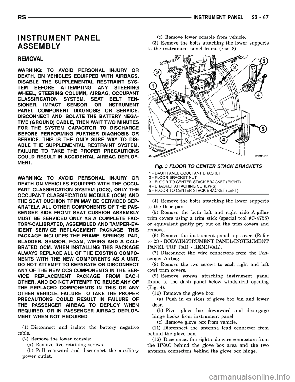
to the instrument panel frame (Fig. 3).
(4) Remove the bolts attaching the lower supports
to the floor pan.
(5) Remove the both left and right side A-pillar
trim covers using a trim stick (special tool #C-4755)
or equivalent gently pry out on the trim covers and
remove.
(6) Remove the instrument panel top cover. (Refer
to 23 - BODY/INSTRUMENT PANEL/INSTRUMENT
PANEL TOP PAD - REMOVAL).
(7) Disconnect the wire connectors from the Pas-
senger Airbag.
(8) Remove the two screws to each right and left
cowl trim covers.
(9) Remove screws attaching instrument panel
frame to the dash panel below windshield opening
(Fig. 4).
(10) Remove the glove box:
(a) Push in on sides of glove box bin and lower
door.
(b) Pivot glove box downward and disengage
hinge hooks from instrument panel.
(c) Remove glove box from vehicle.
(11) Disconnect the antenna lead connector from
behind the glove box.
(12) Disconnect the right side wire connectors from
the HVAC behind the glove box area and the two
antenna connectors behind the glove box hinge.
Fig. 3 FLOOR TO CENTER STACK BRACKETS
1 - DASH PANEL OCCUPANT BRACKET
2 - FLOOR BRACKET NUT
3 - FLOOR TO CENTER STACK BRACKET (RIGHT)
4 - BRACKET ATTACHING SCREW(S)
5 - FLOOR TO CENTER STACK BRACKET (LEFT)
RSINSTRUMENT PANEL23-67
Page 1849 of 2339

(29) Remove both the left and right power mirrors:
(a) Using a trim stick or equivalent, gently pry
out on mirror trim cover.
(b) Open door and remove the three torx retain-
ing screws.
(c) Disconnect the wire connector and remove
mirror from the vehicle.
(30) Feed power mirror wire harness inboard
through the A-pillar.
(31) Loosen the left side roll down bolt (Fig. 8).
(32) Remove the left side A-pillar retaining bolts.
There are two 13 mm bolts and one 10 mm bolt (Fig.
8).
(33) With the help of an assistant remove the
instrument panel from vehicle. Lift the instrument
panel up off the HVAC so you won't damage the seal-
ing surface of the distribution duct.
(34) If the instrument panel is being replaced,
transfer all parts to the new instrument panel
assembly.
INSTALLATION
WARNING: TO AVOID PERSONAL INJURY OR
DEATH, ON VEHICLES EQUIPPED WITH AIRBAGS,
DISABLE THE SUPPLEMENTAL RESTRAINT SYS-
TEM BEFORE ATTEMPTING ANY STEERING
WHEEL, STEERING COLUMN, AIRBAG, OCCUPANT
CLASSIFICATION SYSTEM, SEAT BELT TEN-
SIONER, IMPACT SENSOR, OR INSTRUMENT
PANEL COMPONENT DIAGNOSIS OR SERVICE.
DISCONNECT AND ISOLATE THE BATTERY NEGA-
TIVE (GROUND) CABLE, THEN WAIT TWO MINUTESFOR THE SYSTEM CAPACITOR TO DISCHARGE
BEFORE PERFORMING FURTHER DIAGNOSIS OR
SERVICE. THIS IS THE ONLY SURE WAY TO DIS-
ABLE THE SUPPLEMENTAL RESTRAINT SYSTEM.
FAILURE TO TAKE THE PROPER PRECAUTIONS
COULD RESULT IN ACCIDENTAL AIRBAG DEPLOY-
MENT.
WARNING: TO AVOID PERSONAL INJURY OR
DEATH ON VEHICLES EQUIPPED WITH THE OCCU-
PANT CLASSIFICATION SYSTEM (OCS), ONLY THE
OCCUPANT CLASSIFICATION MODULE (OCM) AND
THE SEAT CUSHION TRIM MAY BE SERVICED SEP-
ARATELY. ALL OTHER COMPONENTS OF THE PAS-
SENGER SIDE FRONT SEAT CUSHION ASSEMBLY
MUST BE SERVICED ONLY AS A COMPLETE FAC-
TORY-CALIBRATED, ASSEMBLED AND TAMPER-EV-
IDENT SERVICE REPLACEMENT PACKAGE. THIS
PACKAGE INCLUDES THE FRAME, SPRINGS, PAD,
BLADDER, SENSOR, FOAM, WIRING AND A CALI-
BRATED OCM. WHEN INSTALLING THIS PACKAGE
ALWAYS REPLACE ALL OF THE EXISTING COMPO-
NENTS WITH THE NEW COMPONENTS AS A UNIT.
DO NOT ATTEMPT TO SEPARATE OR DISCONNECT
ANY OF THE NEW OCS COMPONENTS IN THE SER-
VICE REPLACEMENT PACKAGE FROM EACH
OTHER, AND DO NOT ATTEMPT TO REUSE ANY OF
THE REPLACED COMPONENTS IN THIS OR ANY
OTHER VEHICLE. FAILURE TO TAKE THE PROPER
PRECAUTIONS COULD RESULT IN FAILURE OF
THE PASSENGER AIRBAG TO DEPLOY WHEN
REQUIRED, OR IN PASSENGER AIRBAG DEPLOY-
MENT WHEN NOT REQUIRED.
(1) With the help of an assistant place the instru-
ment panel into vehicle on roll down bolts. As you
roll the instrument panel up, lift the instrument
panel up so the duct work does not bind or bend and
you can set it down on the HVAC housing to get the
proper seal at the distribution duct. Get one bolt
started in the dash panel.
(2) Start the locator screw and install the right
side A-pillar retaining bolts (Fig. 5). There are two 13
mm bolts and one 10 mm bolt.
(3) Install the left side A-pillar retaining bolts.
There are two 13 mm bolts and one 10 mm bolt (Fig.
8).
(4) Tighten the right and left side cowl side roll
down bolt.
(5) Feed power mirror wire harness outboard
through the A-pillar.
(6) Install both the left and right power mirrors:
(a) Connect the wire connector and install the
mirror onto the vehicle.
(b) Install the three torx retaining screws.
(c) Using a firm push, snap the mirror trim
cover into place.
Fig. 9 INSTRUMENT PANEL LOWER
REINFORCEMENT
1 - LOWER RIGHT REINFORCEMENT
2 - STEERING WHEEL ASSEMBLY
23 - 70 INSTRUMENT PANELRS
INSTRUMENT PANEL ASSEMBLY (Continued)
Page 1870 of 2339

HEADLINER
REMOVAL
(1) Remove sun visors and vanity mirrors.
(2) Remove sun visor center supports.
(3) If equipped, remove coat hooks.
(4) If equipped, remove roof rail modules.
(5) Remove A-pillar trim covers. (Refer to 23 -
BODY/INTERIOR/A-PILLAR TRIM - REMOVAL).
(6) Remove B-pillar upper trim covers (Fig. 20).
(Refer to 23 - BODY/INTERIOR/B-PILLAR UPPER
TRIM - REMOVAL).
(7) Remove C-pillar upper trim covers (Fig. 21).
(Refer to 23 - BODY/INTERIOR/C-PILLAR TRIM -
REMOVAL).
(8) Remove D-pillar trim covers. (Refer to 23 -
BODY/INTERIOR/RIGHT D-PILLAR TRIM PANEL -
REMOVAL) and (Refer to 23 - BODY/INTERIOR/
LEFT D-PILLAR TRIM PANEL - REMOVAL).
(9) Remove liftgate opening header trim.
(10) If equipped, remove overhead console screws.
(11) If equipped, remove reading lamps.
(12) Remove dome lamp.
(13) Remove push in locking fasteners attaching
headlining to rear roof header and roof bows (Fig.
22).(14) Remove wiring connections.
(15) Remove headlining from roof (Fig. 23), (Fig.
24), (Fig. 25), and (Fig. 26).
(16) Extract headlining through liftgate opening.
Fig. 20 HEADLINER AT B-PILLAR
1 - FRONT AND SLIDING DOOR WEATHERSTRIP SEAL
2 - B-PILLAR UPPER TRIM PANEL
Fig. 21 HEADLINER AT C-PILLAR
1 - SLIDING DOOR WEATHERSTRIP
2 - C-PILLAR UPPER TRIM PANEL
3 - REAR QUARTER WINDOW OPENING WEATHERSTRIP
Fig. 22 HEADLINER PUSH PINS
RSINTERIOR23-91
Page 1871 of 2339

INSTALLATION
(1) Insert headlining through liftgate opening (Fig.
23), (Fig. 24), (Fig. 25), and (Fig. 26).
(2) Place headlining in position on roof.
(3) Connect wire connectors.
(4) Install left sun visor support.
(5) Install push in locking fasteners attaching
headlining to rear roof header and bows (Fig. 22).
(6) Install right sun visor support.
(7) Install sun visors and vanity mirrors.
(8) If equipped, install roof rail modules.
(9) If equipped, install coat hooks.
(10) Install dome lamp.
(11) If equipped, install reading lamp.
(12) If equipped, install overhead console.
(13) Install liftgate opening header trim.
(14) Install D-pillar trim covers. (Refer to 23 -
BODY/INTERIOR/LEFT D-PILLAR TRIM PANEL -
INSTALLATION), and (Refer to 23 - BODY/INTERI-
OR/RIGHT D-PILLAR TRIM PANEL - INSTALLA-
TION).(15) Install C-pillar upper trim covers. (Refer to 23
- BODY/INTERIOR/C-PILLAR TRIM - INSTALLA-
TION).
(16) Install B-pillar upper trim covers. (Refer to 23
- BODY/INTERIOR/B-PILLAR UPPER TRIM -
INSTALLATION).
(17) Install A-pillar trim covers. (Refer to 23 -
BODY/INTERIOR/A-PILLAR TRIM - INSTALLA-
TION).
Fig. 23 HEADLINER WITH SIDE CURTAINS
1 - 4-WAY LOCATOR AT FRONT OF HEADLINER
2 - PUSH IN CLIPS ON SUN VISOR RETAINER RACKET AND
TWO SCREWS IN SUN VISOR SWIVEL BRACKET
3 - ONE SCREW IN OVER HEAD CONSOLE
4 - PUSH PINS ATTACHING HEADLINER TO OVERHEAD5-2WAYLOCATOR AT REAR OF HEADLINER
6 - COAT HANGER HOOKS
7 - 2-WAY LOCATORS
8 - WIRE HARNESS
23 - 92 INTERIORRS
HEADLINER (Continued)