instrument panel CHRYSLER VOYAGER 2005 Service Manual
[x] Cancel search | Manufacturer: CHRYSLER, Model Year: 2005, Model line: VOYAGER, Model: CHRYSLER VOYAGER 2005Pages: 2339, PDF Size: 59.69 MB
Page 6 of 2339
FASTENER USAGE
DESCRIPTION
FASTENER USAGE
WARNING: USE OF AN INCORRECT FASTENER
MAY RESULT IN COMPONENT DAMAGE OR PER-
SONAL INJURY.
Fasteners and torque specifications references in
this Service Manual are identified in metric and SAE
format.
During any maintenance or repair procedures, it is
important to salvage all fasteners (nuts, bolts, etc.)
for reassembly. If the fastener is not salvageable, a
fastener of equivalent specification must be used.
THREADED HOLE REPAIR
Most stripped threaded holes can be repaired using
a Helicoilt. Follow the vehicle or Helicoiltrecommen-
dations for application and repair procedures.
INTERNATIONAL SYMBOLS
DESCRIPTION
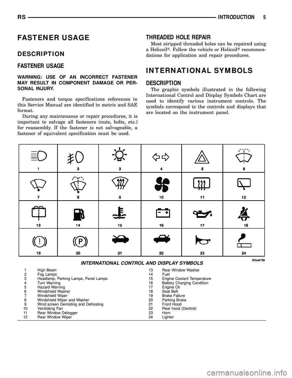
The graphic symbols illustrated in the following
International Control and Display Symbols Chart are
used to identify various instrument controls. The
symbols correspond to the controls and displays that
are located on the instrument panel.
INTERNATIONAL CONTROL AND DISPLAY SYMBOLS
1 High Beam 13 Rear Window Washer
2 Fog Lamps 14 Fuel
3 Headlamp, Parking Lamps, Panel Lamps 15 Engine Coolant Temperature
4 Turn Warning 16 Battery Charging Condition
5 Hazard Warning 17 Engine Oil
6 Windshield Washer 18 Seat Belt
7 Windshield Wiper 19 Brake Failure
8 Windshield Wiper and Washer 20 Parking Brake
9 Wind screen Demisting and Defrosting 21 Front Hood
10 Ventilating Fan 22 Rear hood (Decklid)
11 Rear Window Defogger 23 Horn
12 Rear Window Wiper 24 Lighter
RSINTRODUCTION5
Page 10 of 2339
Individual Torque Charts appear within many or
the Groups. Refer to the Standard Torque Specifica-
tions Chart for torque references not listed in the
individual torque charts.
VEHICLE IDENTIFICATION
NUMBER
DESCRIPTION
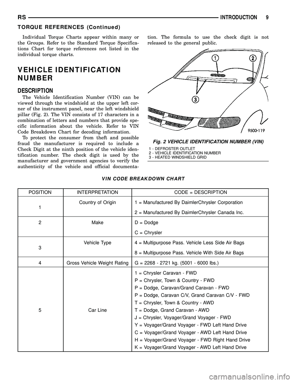
The Vehicle Identification Number (VIN) can be
viewed through the windshield at the upper left cor-
ner of the instrument panel, near the left windshield
pillar (Fig. 2). The VIN consists of 17 characters in a
combination of letters and numbers that provide spe-
cific information about the vehicle. Refer to VIN
Code Breakdown Chart for decoding information.
To protect the consumer from theft and possible
fraud the manufacturer is required to include a
Check Digit at the ninth position of the vehicle iden-
tification number. The check digit is used by the
manufacturer and government agencies to verify the
authenticity of the vehicle and official documenta-tion. The formula to use the check digit is not
released to the general public.
VIN CODE BREAKDOWN CHART
POSITION INTERPRETATION CODE = DESCRIPTION
1Country of Origin 1 = Manufactured By DaimlerChrysler Corporation
2 = Manufactured By DaimlerChrysler Canada Inc.
2 Make D = Dodge
C = Chrysler
3Vehicle Type 4 = Multipurpose Pass. Vehicle Less Side Air Bags
8 = Multipurpose Pass. Vehicle With Side Air Bags
4 Gross Vehicle Weight Rating G = 2268 - 2721 kg. (5001 - 6000 lbs.)
5 Car Line1 = Chrysler Caravan - FWD
P = Chrysler, Town & Country - FWD
P = Dodge, Caravan/Grand Caravan - FWD
P = Dodge, Caravan C/V, Grand Caravan C/V - FWD
T = Chrysler, Town & Country - AWD
T = Dodge, Grand Caravan - AWD
J = Chrysler, Voyager/Grand Voyager - FWD
Y = Voyager/Grand Voyager - FWD Left Hand Drive
C = Voyager/Grand Voyager - AWD Left Hand Drive
H = Voyager/Grand Voyager - FWD Right Hand Drive
K = Voyager/Grand Voyager - AWD Left Hand Drive
Fig. 2 VEHICLE IDENTIFICATION NUMBER (VIN)
1 - DEFROSTER OUTLET
2 - VEHICLE IDENTIFICATION NUMBER
3 - HEATED WINDSHIELD GRID
RSINTRODUCTION9
TORQUE REFERENCES (Continued)
Page 151 of 2339
CAUTION: When tightening the primary and sec-
ondary brake tube nuts at master cylinder, be sure
brake tubes do not contact any other components
within the vehicle and that there is slack in the flex-
ible sections of the tubes. This is required due to
the movement between the ABS ICU and the master
cylinder while the vehicle is in motion.
(4) Connect primary and secondary brake tubes to
master cylinder primary and secondary ports (Fig.
50). Brake tubes must be held securely when tight-
ened to control orientation of flex section. Tighten
tube nuts to a torque of 17 N´m (145 in. lbs.).
(5) Install wiring harness connector to brake fluid
level switch mounted in brake fluid reservoir (Fig.
46).
(6) Install battery, clamp and nut.
(7) Install battery shield.
(8) Connect positive battery terminal.
(9) Connect negative battery terminal.
(10) Fill master cylinder with clean, fresh Mopart
Brake Fluid or equivalent.
(11) Road test vehicle to ensure proper operation of
brakes.
PEDALS - ADJUSTABLE
REMOVAL
NOTE: Before proceeding, review all Steering Col-
umn and Airbag Warnings and Cautions. (Refer to
19 - STEERING/COLUMN - WARNING)(Refer to 8 -
ELECTRICAL/RESTRAINTS - WARNING)
(1) Move driver's seat to full rearward position.
(2) Disconnect negative battery cable from battery
post and isolate.
(3) Remove throttle cable from throttle body lever.
(Refer to 14 - FUEL SYSTEM/FUEL INJECTION/
THROTTLE CONTROL CABLE - REMOVAL)
(4) Remove screws securing lower steering column
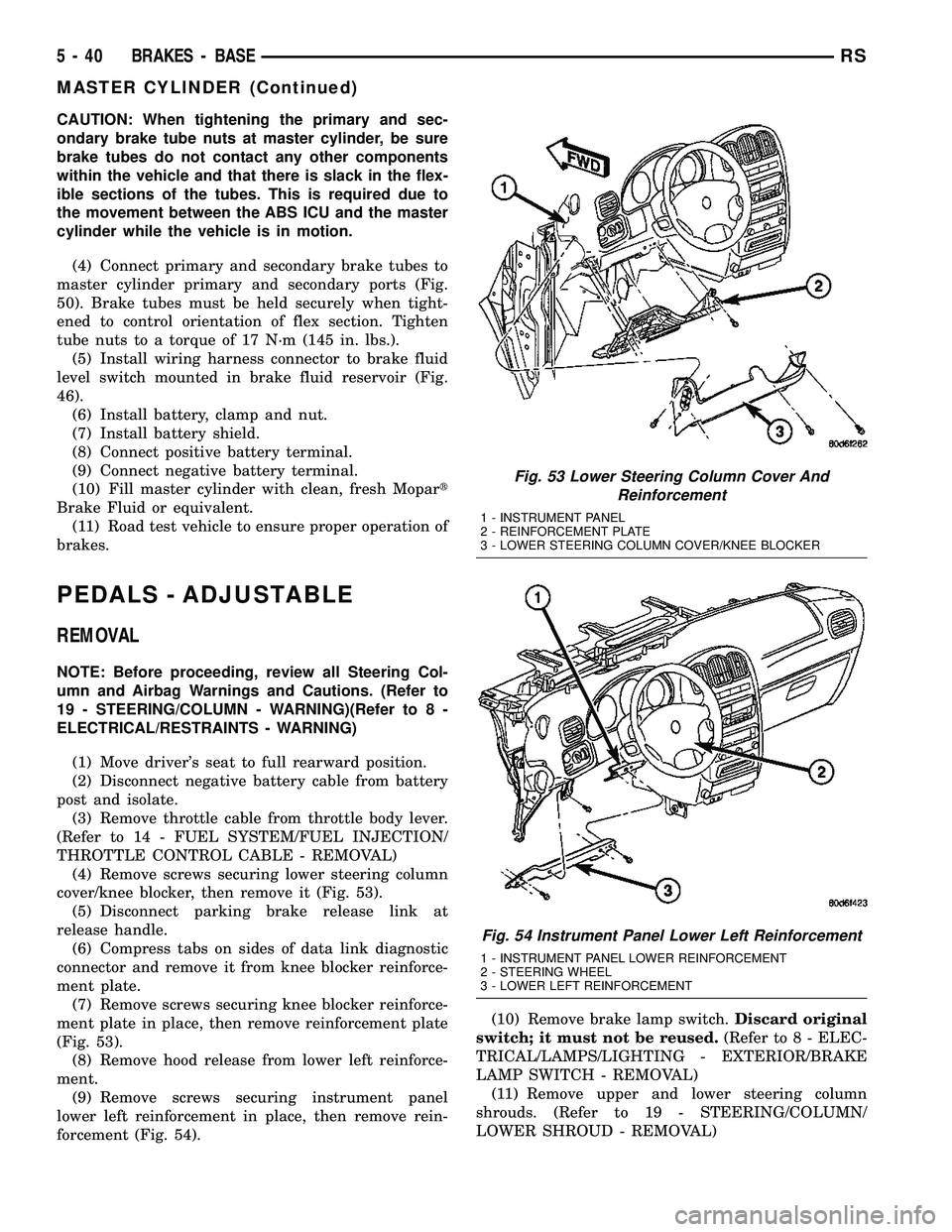
cover/knee blocker, then remove it (Fig. 53).
(5) Disconnect parking brake release link at
release handle.
(6) Compress tabs on sides of data link diagnostic
connector and remove it from knee blocker reinforce-
ment plate.
(7) Remove screws securing knee blocker reinforce-
ment plate in place, then remove reinforcement plate
(Fig. 53).
(8) Remove hood release from lower left reinforce-
ment.
(9) Remove screws securing instrument panel
lower left reinforcement in place, then remove rein-
forcement (Fig. 54).(10) Remove brake lamp switch.Discard original
switch; it must not be reused.(Refer to 8 - ELEC-
TRICAL/LAMPS/LIGHTING - EXTERIOR/BRAKE
LAMP SWITCH - REMOVAL)
(11) Remove upper and lower steering column
shrouds. (Refer to 19 - STEERING/COLUMN/
LOWER SHROUD - REMOVAL)
Fig. 53 Lower Steering Column Cover And
Reinforcement
1 - INSTRUMENT PANEL
2 - REINFORCEMENT PLATE
3 - LOWER STEERING COLUMN COVER/KNEE BLOCKER
Fig. 54 Instrument Panel Lower Left Reinforcement
1 - INSTRUMENT PANEL LOWER REINFORCEMENT
2 - STEERING WHEEL
3 - LOWER LEFT REINFORCEMENT
5 - 40 BRAKES - BASERS
MASTER CYLINDER (Continued)
Page 154 of 2339
INSTALLATION
(1) Install adjustable pedals assembly under
instrument panel.
(2) Attach throttle cable to accelerator pedal using
cable retainer.
(3) Install two upper mounting bolts attaching
pedals assembly to steering column support bracket
on dash panel.Do not fully tighten at this time.
(4) Install four nuts attaching pedals assembly and
power brake booster to dash panel (Fig. 61).
(5) Tighten four booster mounting nuts and two
upper mounting bolts to 28 N´m (21 ft. lbs.) torque.
(6) Route pedal adjuster cable up and over right
side of pedals assembly and steering column bracket,
then down through hole in steering column bracket
as shown (Fig. 60). Attach end of cable to gear box.
(7) Place adjuster cable through loop on right side
of steering column bracket as shown (Fig. 60).
(8) Install booster input rod onto brake pedal pin
and install a NEW retaining clip.
(9) Connect wiring connector connecting vehicle
wiring harness to pedal wiring harness (Fig. 58).
(10) Connect routing clips retaining vehicle wiring
harness to pedal wiring harness (Fig. 58).
(11) Install brake lamp switch bracket on pedals
assembly. Tighten mounting nuts to 6 N´m (50 in.
lbs.) torque.
(12) Install dash seal silencer shell over steering
column intermediate shaft and fasten in place (Fig.
57).
(13) Install steering column onto lower mounting
studs with nuts started, then install column onto
upper mounting studs and install two upper mount-
ing nuts. Tighten upper, then lower mounting nuts to
12 N´m (105 in. lbs.) torque.
(14) Install column shaft coupling onto intermedi-
ate shaft and install pinch bolt. Make sure rounded
side of intermediate shaft is matched to the curva-
ture of the coupling. Tighten pinch bolt to 28 N´m
(250 in. lbs.) torque.
(15) Remove retainer holding steering wheel in
place on steering column.
(16) Attach shift cable to bracket on column.
(17) Connect shift cable end to shift lever mecha-
nism pin (Fig. 55).
(18) If equipped, connect PRNDL cable to end of
shift lever mechanism pin and column bracket (Fig.
55).(19) Connect column wiring harness connectors (as
equipped) to SKIM, BTSI solenoid, ignition switch,
multi-function switch, and clockspring.
(20) Install lower and upper steering column
shrouds. (Refer to 19 - STEERING/COLUMN/
LOWER SHROUD - INSTALLATION)
CAUTION: Do not reuse the original brake lamp
switch. The switch can only be adjusted once. That
is during initial installation of the switch. If the
switch is not adjusted properly or has been
removed for some service, a new switch must be
installed and adjusted.
(21) Install and adjust NEW brake lamp switch.
(Refer to 8 - ELECTRICAL/LAMPS/LIGHTING -
EXTERIOR/BRAKE LAMP SWITCH - INSTALLA-
TION)
(22) Install instrument panel lower left reinforce-
ment (Fig. 54).
(23) Attach hood release to lower left reinforce-
ment.
(24) Install knee blocker reinforcement plate (Fig.
53).
(25) Connect parking brake release link to release
handle.
(26) Install data link diagnostic connector to
mounting hole in reinforcement plate.
(27) Install lower steering column cover/knee
blocker (Fig. 53).
(28) Install throttle cable onto throttle body lever.
(Refer to 14 - FUEL SYSTEM/FUEL INJECTION/
THROTTLE CONTROL CABLE - INSTALLATION)
NOTE: When reconnecting the battery on a vehicle
that has had the airbag module removed, the fol-
lowing procedure should be used.
(29) Reconnect ground cable to negative post of
battery following special Diagnosis And Testing pro-
cedure. (Refer to 8 - ELECTRICAL/RESTRAINTS -
DIAGNOSIS AND TESTING)
(30) Test operation of adjustable pedals and all
functions that are steering column operated. If appli-
cable, reset radio and clock.
(31) Road test the vehicle to ensure proper opera-
tion of steering and brake systems.
RSBRAKES - BASE5-43
PEDALS - ADJUSTABLE (Continued)
Page 155 of 2339
PEDAL TORQUE SHAFT - RHD
REMOVAL
(1) Remove the instrument panel. (Refer to 23 -
BODY/INSTRUMENT PANEL/INSTRUMENT
PANEL ASSEMBLY - REMOVAL)
(2) Remove the HVAC housing. (Refer to 24 -
HEATING & AIR CONDITIONING/DISTRIBUTION/
HVAC HOUSING - REMOVAL)
(3) Remove the retaining clip at the torque shaft
end of the brake pedal-to-torque shaft link. Remove
the link from the torque shaft. Discard the retaining
clip. It is not to be reused. Replace with a new clip
when reassembled.
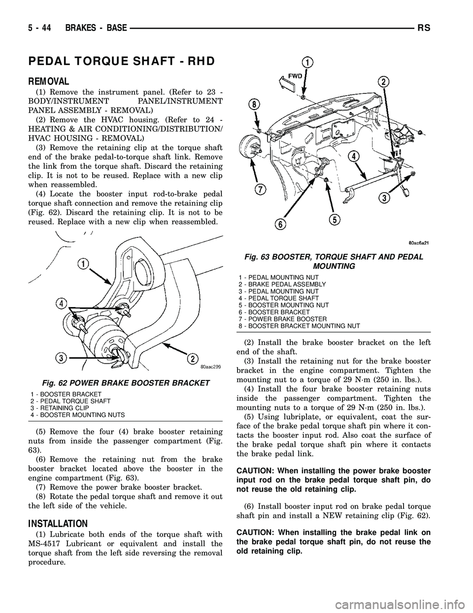
(4) Locate the booster input rod-to-brake pedal
torque shaft connection and remove the retaining clip
(Fig. 62). Discard the retaining clip. It is not to be
reused. Replace with a new clip when reassembled.
(5) Remove the four (4) brake booster retaining
nuts from inside the passenger compartment (Fig.
63).
(6) Remove the retaining nut from the brake
booster bracket located above the booster in the
engine compartment (Fig. 63).
(7) Remove the power brake booster bracket.
(8) Rotate the pedal torque shaft and remove it out
the left side of the vehicle.
INSTALLATION
(1) Lubricate both ends of the torque shaft with
MS-4517 Lubricant or equivalent and install the
torque shaft from the left side reversing the removal
procedure.(2) Install the brake booster bracket on the left
end of the shaft.
(3) Install the retaining nut for the brake booster
bracket in the engine compartment. Tighten the
mounting nut to a torque of 29 N´m (250 in. lbs.).
(4) Install the four brake booster retaining nuts
inside the passenger compartment. Tighten the
mounting nuts to a torque of 29 N´m (250 in. lbs.).
(5) Using lubriplate, or equivalent, coat the sur-
face of the brake pedal torque shaft pin where it con-
tacts the booster input rod. Also coat the surface of
the brake pedal torque shaft pin where it contacts
the brake pedal link.
CAUTION: When installing the power brake booster
input rod on the brake pedal torque shaft pin, do
not reuse the old retaining clip.
(6) Install booster input rod on brake pedal torque
shaft pin and install a NEW retaining clip (Fig. 62).
CAUTION: When installing the brake pedal link on
the brake pedal torque shaft pin, do not reuse the
old retaining clip.
Fig. 62 POWER BRAKE BOOSTER BRACKET
1 - BOOSTER BRACKET
2 - PEDAL TORQUE SHAFT
3 - RETAINING CLIP
4 - BOOSTER MOUNTING NUTS
Fig. 63 BOOSTER, TORQUE SHAFT AND PEDAL
MOUNTING
1 - PEDAL MOUNTING NUT
2 - BRAKE PEDAL ASSEMBLY
3 - PEDAL MOUNTING NUT
4 - PEDAL TORQUE SHAFT
5 - BOOSTER MOUNTING NUT
6 - BOOSTER BRACKET
7 - POWER BRAKE BOOSTER
8 - BOOSTER BRACKET MOUNTING NUT
5 - 44 BRAKES - BASERS
Page 156 of 2339
(7) Connect the brake pedal link to the torque
shaft. Install a NEW retaining clip at the torque
shaft end of the brake pedal-to-torque shaft link.
(8) Install the HVAC housing. (Refer to 24 - HEAT-
ING & AIR CONDITIONING/DISTRIBUTION/HVAC
HOUSING - INSTALLATION)
(9) Install the instrument panel. (Refer to 23 -
BODY/INSTRUMENT PANEL/INSTRUMENT
PANEL ASSEMBLY - INSTALLATION)
CAUTION: Do not reuse the original brake lamp
switch. The switch can only be adjusted once. That
is during initial installation of the switch. If the
switch is not adjusted properly or has been
removed for some service, a new switch must be
installed and adjusted.
(10) Remove and replace the brake lamp switch
with a NEW switch. (Refer to 8 - ELECTRICAL/
LAMPS/LIGHTING - EXTERIOR/BRAKE LAMP
SWITCH - REMOVAL), (Refer to 8 - ELECTRICAL/
LAMPS/LIGHTING - EXTERIOR/BRAKE LAMP
SWITCH - INSTALLATION)
(11) Road test vehicle to ensure proper operation of
the brakes.
POWER BRAKE BOOSTER
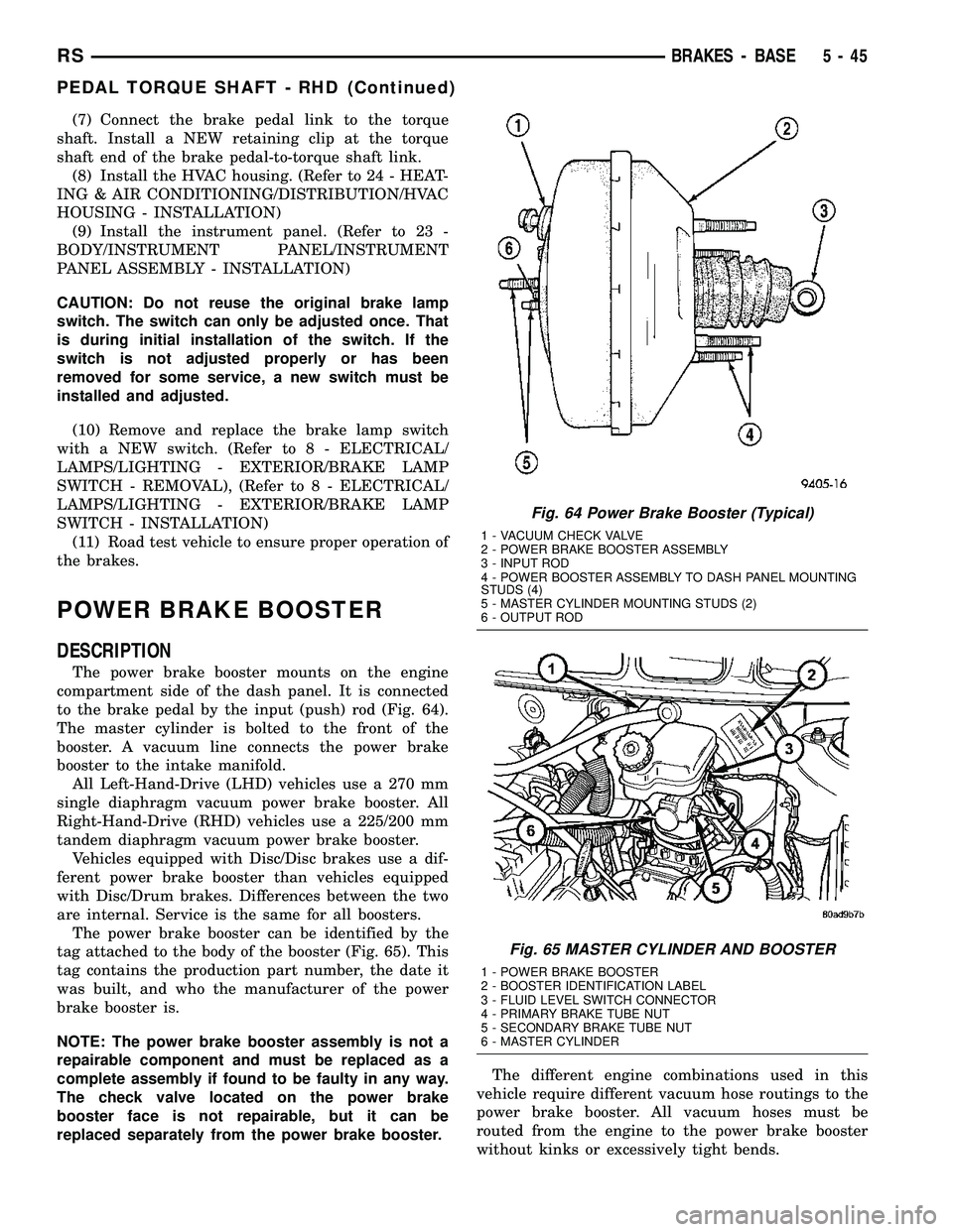
DESCRIPTION
The power brake booster mounts on the engine
compartment side of the dash panel. It is connected
to the brake pedal by the input (push) rod (Fig. 64).
The master cylinder is bolted to the front of the
booster. A vacuum line connects the power brake
booster to the intake manifold.
All Left-Hand-Drive (LHD) vehicles use a 270 mm
single diaphragm vacuum power brake booster. All
Right-Hand-Drive (RHD) vehicles use a 225/200 mm
tandem diaphragm vacuum power brake booster.
Vehicles equipped with Disc/Disc brakes use a dif-
ferent power brake booster than vehicles equipped
with Disc/Drum brakes. Differences between the two
are internal. Service is the same for all boosters.
The power brake booster can be identified by the
tag attached to the body of the booster (Fig. 65). This
tag contains the production part number, the date it
was built, and who the manufacturer of the power
brake booster is.
NOTE: The power brake booster assembly is not a
repairable component and must be replaced as a
complete assembly if found to be faulty in any way.
The check valve located on the power brake
booster face is not repairable, but it can be
replaced separately from the power brake booster.The different engine combinations used in this
vehicle require different vacuum hose routings to the
power brake booster. All vacuum hoses must be
routed from the engine to the power brake booster
without kinks or excessively tight bends.
Fig. 64 Power Brake Booster (Typical)
1 - VACUUM CHECK VALVE
2 - POWER BRAKE BOOSTER ASSEMBLY
3 - INPUT ROD
4 - POWER BOOSTER ASSEMBLY TO DASH PANEL MOUNTING
STUDS (4)
5 - MASTER CYLINDER MOUNTING STUDS (2)
6 - OUTPUT ROD
Fig. 65 MASTER CYLINDER AND BOOSTER
1 - POWER BRAKE BOOSTER
2 - BOOSTER IDENTIFICATION LABEL
3 - FLUID LEVEL SWITCH CONNECTOR
4 - PRIMARY BRAKE TUBE NUT
5 - SECONDARY BRAKE TUBE NUT
6 - MASTER CYLINDER
RSBRAKES - BASE5-45
PEDAL TORQUE SHAFT - RHD (Continued)
Page 159 of 2339
(17) Inside vehicle, remove silencer panel under
instrument panel below steering column.
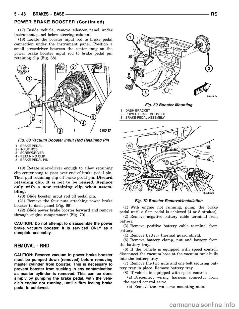
(18) Locate the booster input rod to brake pedal
connection under the instrument panel. Position a
small screwdriver between the center tang on the
power brake booster input rod to brake pedal pin
retaining clip (Fig. 68).
(19) Rotate screwdriver enough to allow retaining
clip center tang to pass over end of brake pedal pin.
Then pull retaining clip off brake pedal pin.Discard
retaining clip. It is not to be reused. Replace
only with a new retaining clip when assem-
bling.
(20) Slide booster input rod off pedal pin.
(21) Remove the four nuts attaching power brake
booster to dash panel (Fig. 69).
(22) Slide power brake booster forward and remove
through engine compartment (Fig. 70).
CAUTION: Do not attempt to disassemble the power
brake vacuum booster. It is serviced ONLY as a
complete assembly.
REMOVAL - RHD
CAUTION: Reserve vacuum in power brake booster
must be pumped down (removed) before removing
master cylinder from booster. This is necessary to
prevent booster from sucking in any contamination
as master cylinder is removed. This can be done
simply by pumping the brake pedal, with the vehi-
cle's engine not running, until a firm feeling brake
pedal is achieved.(1) With engine not running, pump the brake
pedal until a firm pedal is achieved (4 or 5 strokes).
(2) Remove negative battery cable terminal from
battery.
(3) Remove positive battery cable terminal from
battery.
(4) Remove battery thermal guard shield.
(5) Remove battery clamp, nut and battery from
the battery tray.
(6) If the vehicle is equipped with speed control,
disconnect the vacuum hose at the vacuum tank built
into the battery tray.
(7) Remove the two nuts and one bolt securing bat-
tery tray in place. Remove battery tray.
(8) If vehicle is equipped with speed control:
(a) Disconnect wiring harness connector from
the speed control servo.
(b) Remove the two servo mounting nuts.
Fig. 68 Vacuum Booster Input Rod Retaining Pin
1 - BRAKE PEDAL
2 - INPUT ROD
3 - SCREWDRIVER
4 - RETAINING CLIP
5 - BRAKE PEDAL PIN
Fig. 69 Booster Mounting
1 - DASH BRACKET
2 - POWER BRAKE BOOSTER
3 - BRAKE PEDAL ASSEMBLY
Fig. 70 Booster Removal/Installation
5 - 48 BRAKES - BASERS
POWER BRAKE BOOSTER (Continued)
Page 160 of 2339
(c) Lay speed control servo off to the side, out of
the way.
(9) If the vehicle is equipped with the 2.5L diesel
engine, remove the coolant recovery pressure con-
tainer and bracket. (Refer to 7 - COOLING/ENGINE/
COOLANT RECOVERY PRESS CONTAINER -
REMOVAL)
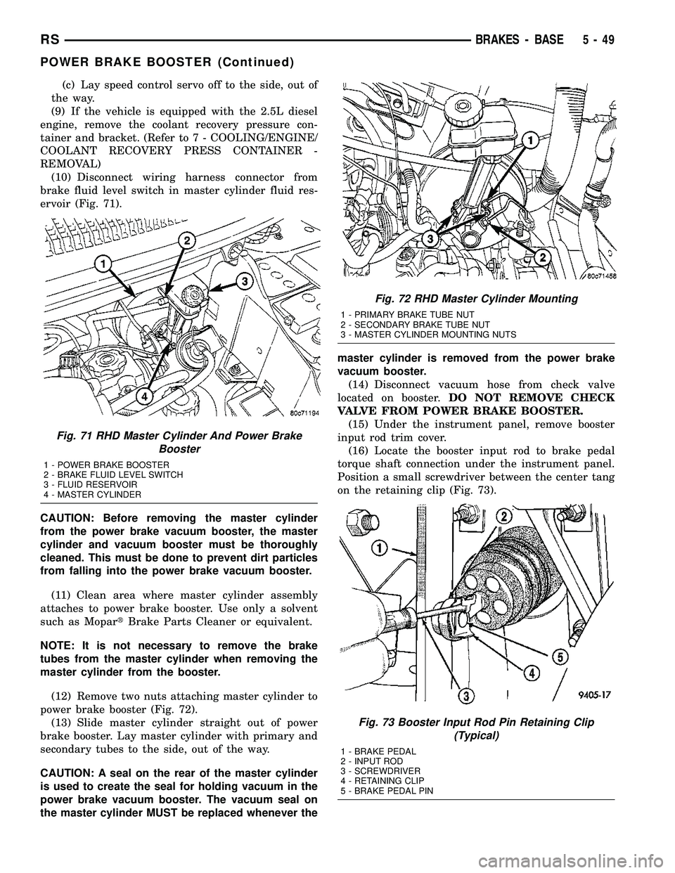
(10) Disconnect wiring harness connector from
brake fluid level switch in master cylinder fluid res-
ervoir (Fig. 71).
CAUTION: Before removing the master cylinder
from the power brake vacuum booster, the master
cylinder and vacuum booster must be thoroughly
cleaned. This must be done to prevent dirt particles
from falling into the power brake vacuum booster.
(11) Clean area where master cylinder assembly
attaches to power brake booster. Use only a solvent
such as MopartBrake Parts Cleaner or equivalent.
NOTE: It is not necessary to remove the brake
tubes from the master cylinder when removing the
master cylinder from the booster.
(12) Remove two nuts attaching master cylinder to
power brake booster (Fig. 72).
(13) Slide master cylinder straight out of power
brake booster. Lay master cylinder with primary and
secondary tubes to the side, out of the way.
CAUTION: A seal on the rear of the master cylinder
is used to create the seal for holding vacuum in the
power brake vacuum booster. The vacuum seal on
the master cylinder MUST be replaced whenever themaster cylinder is removed from the power brake
vacuum booster.
(14) Disconnect vacuum hose from check valve
located on booster.DO NOT REMOVE CHECK
VALVE FROM POWER BRAKE BOOSTER.
(15) Under the instrument panel, remove booster
input rod trim cover.
(16) Locate the booster input rod to brake pedal
torque shaft connection under the instrument panel.
Position a small screwdriver between the center tang
on the retaining clip (Fig. 73).
Fig. 71 RHD Master Cylinder And Power Brake
Booster
1 - POWER BRAKE BOOSTER
2 - BRAKE FLUID LEVEL SWITCH
3 - FLUID RESERVOIR
4 - MASTER CYLINDER
Fig. 72 RHD Master Cylinder Mounting
1 - PRIMARY BRAKE TUBE NUT
2 - SECONDARY BRAKE TUBE NUT
3 - MASTER CYLINDER MOUNTING NUTS
Fig. 73 Booster Input Rod Pin Retaining Clip
(Typical)
1 - BRAKE PEDAL
2 - INPUT ROD
3 - SCREWDRIVER
4 - RETAINING CLIP
5 - BRAKE PEDAL PIN
RSBRAKES - BASE5-49
POWER BRAKE BOOSTER (Continued)
Page 162 of 2339
CAUTION: Do not reuse the original brake lamp
switch. The switch can only be adjusted once. That
is during initial installation of the switch. If the
switch is not adjusted properly or has been
removed for some service, a new switch must be
installed and adjusted.
(5) Remove and replace the brake lamp switch
with a NEW switch. (Refer to 8 - ELECTRICAL/
LAMPS/LIGHTING - EXTERIOR/BRAKE LAMP
SWITCH - REMOVAL), (Refer to 8 - ELECTRICAL/
LAMPS/LIGHTING - EXTERIOR/BRAKE LAMP
SWITCH - INSTALLATION)
(6) Install the silencer panel below the steering
column.
(7) Connect vacuum hose to check valve on power
brake booster.
CAUTION: The master cylinder (and its rear seal) is
used to create the seal for holding vacuum in the
vacuum booster. The vacuum seal on the master
cylinder MUST be replaced with a NEW seal when-
ever the master cylinder is removed from the vac-
uum booster.
CAUTION: When removing the vacuum seal from
the master cylinder do not use a sharp tool.
(8) Using a soft tool such as a trim stick, remove
the vacuum seal from the master cylinder mounting
flange.
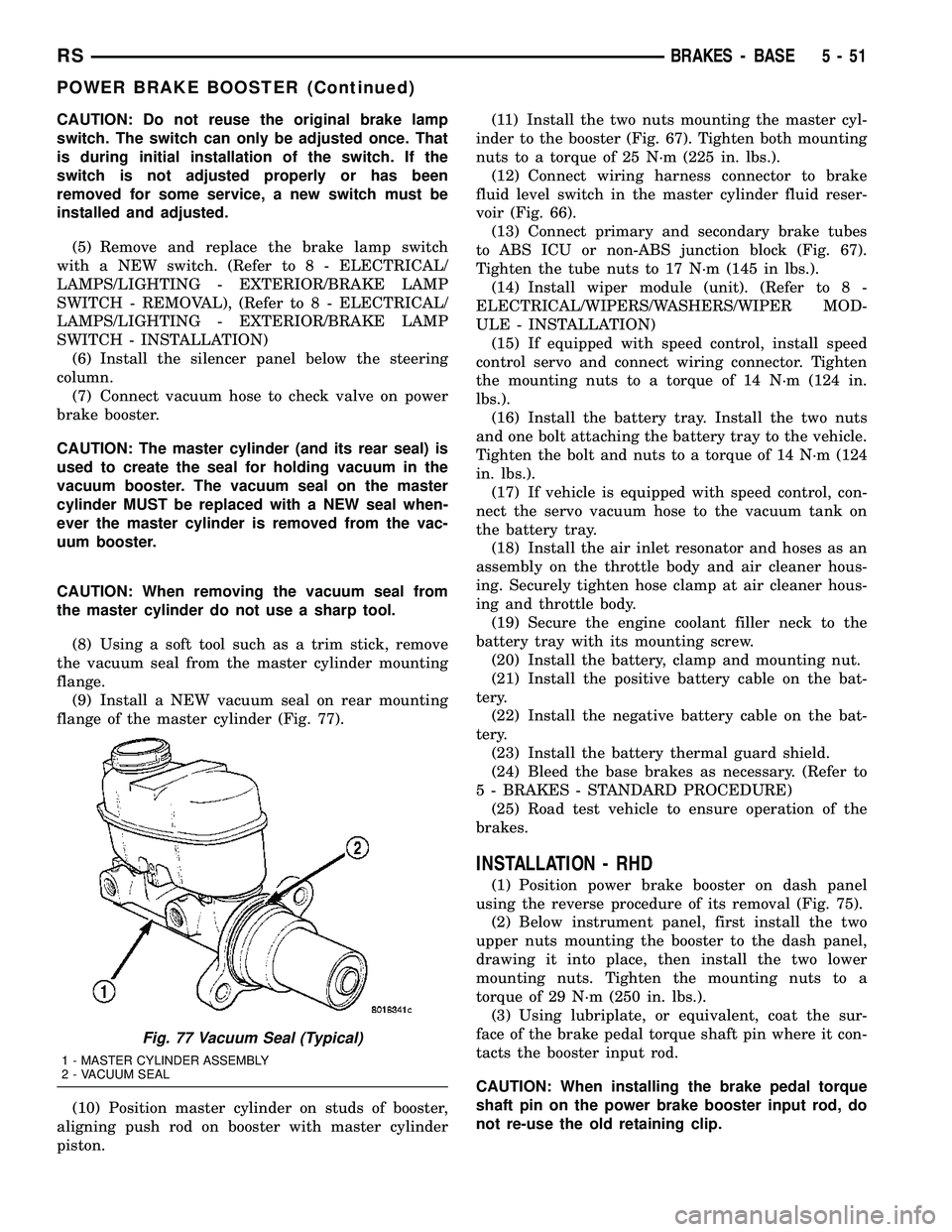
(9) Install a NEW vacuum seal on rear mounting
flange of the master cylinder (Fig. 77).
(10) Position master cylinder on studs of booster,
aligning push rod on booster with master cylinder
piston.(11) Install the two nuts mounting the master cyl-
inder to the booster (Fig. 67). Tighten both mounting
nuts to a torque of 25 N´m (225 in. lbs.).
(12) Connect wiring harness connector to brake
fluid level switch in the master cylinder fluid reser-
voir (Fig. 66).
(13) Connect primary and secondary brake tubes
to ABS ICU or non-ABS junction block (Fig. 67).
Tighten the tube nuts to 17 N´m (145 in lbs.).
(14) Install wiper module (unit). (Refer to 8 -
ELECTRICAL/WIPERS/WASHERS/WIPER MOD-
ULE - INSTALLATION)
(15) If equipped with speed control, install speed
control servo and connect wiring connector. Tighten
the mounting nuts to a torque of 14 N´m (124 in.
lbs.).
(16) Install the battery tray. Install the two nuts
and one bolt attaching the battery tray to the vehicle.
Tighten the bolt and nuts to a torque of 14 N´m (124
in. lbs.).
(17) If vehicle is equipped with speed control, con-
nect the servo vacuum hose to the vacuum tank on
the battery tray.
(18) Install the air inlet resonator and hoses as an
assembly on the throttle body and air cleaner hous-
ing. Securely tighten hose clamp at air cleaner hous-
ing and throttle body.
(19) Secure the engine coolant filler neck to the
battery tray with its mounting screw.
(20) Install the battery, clamp and mounting nut.
(21) Install the positive battery cable on the bat-
tery.
(22) Install the negative battery cable on the bat-
tery.
(23) Install the battery thermal guard shield.
(24) Bleed the base brakes as necessary. (Refer to
5 - BRAKES - STANDARD PROCEDURE)
(25) Road test vehicle to ensure operation of the
brakes.
INSTALLATION - RHD
(1) Position power brake booster on dash panel
using the reverse procedure of its removal (Fig. 75).
(2) Below instrument panel, first install the two
upper nuts mounting the booster to the dash panel,
drawing it into place, then install the two lower
mounting nuts. Tighten the mounting nuts to a
torque of 29 N´m (250 in. lbs.).
(3) Using lubriplate, or equivalent, coat the sur-
face of the brake pedal torque shaft pin where it con-
tacts the booster input rod.
CAUTION: When installing the brake pedal torque
shaft pin on the power brake booster input rod, do
not re-use the old retaining clip.
Fig. 77 Vacuum Seal (Typical)
1 - MASTER CYLINDER ASSEMBLY
2 - VACUUM SEAL
RSBRAKES - BASE5-51
POWER BRAKE BOOSTER (Continued)
Page 186 of 2339
INSTALLATION - LEFT REAR
(1) Install the rear parking brake cable in the
brake support plate. Insert cable housing retainer
into brake support plate making certain that cable
housing retainer fingers lock the housing and
retainer firmly into place.
(2) Attach the parking brake cable onto the park
brake actuator lever.
(3) Install the brake shoes on the rear brake sup-
port plate. (Refer to 5 - BRAKES/HYDRAULIC/ME-
CHANICAL/BRAKE PADS/SHOES -
INSTALLATION).
(4) Insert cable housing retainer into body outrig-
ger bracket making certain that cable housing
retainer fingers lock the housing firmly into place.
(5) Connect rear parking brake cable to the equal-
izer bracket (Fig. 115).
(6) Install brake drum, and wheel and tire assem-
bly.
(7) Remove the locking pliers from the front park
brake cable. This will automatically adjust the park
brake cables.
(8) Apply and release park brake pedal 1 time.
This will seat the park brake cables.
INSTALLATION - FOLD-IN-FLOOR SEATING
(1) Pass the leading end of the rear parking brake
cable through the hole in the end of the intermediate
bracket (Fig. 123). Press the cable housing retainer
through the hole until the fingers on the retainer
lock it into place.
(2) Route the cable back toward the brake assem-
bly placing it in the routing clip fastened to the
underbody of the vehicle (Fig. 119). Make sure to
stay to the inside of the left stabilizer bar link while
routing either cable.
(3) If the right rear cable is being serviced, install
screws, attaching the cable routing clamps to the
rear axle (Fig. 120).
(4) Pass the cable through the hole in the brake
adapter and hook the cable eyelet to the shoe lever
(Fig. 121).
(5) Install the screw fastening the cable to the rear
brake adapter (Fig. 121).
(6) Pull straight back on the front cable button
(and pliers) and properly attach the equalizer to all
three parking brake cables (Fig. 118).
(7) Remove the locking pliers from the front park-
ing brake cable and allow the automatic self-adjust-
ing mechanism in the lever to take up any slack.
(8) Lower the vehicle.
(9) Apply and release park brake pedal 1 time.
This will seat the parking brake cables.
LEVER - PARKING BRAKE
REMOVAL
(1) Manually release the automatic self-adjusting
mechanism tension of the parking brake lever (pedal)
assembly. (Refer to 5 - BRAKES/PARKING BRAKE -
STANDARD PROCEDURE).
(2) Disconnect negative (ground) cable from the
battery and isolate cable from battery terminal.
(3) Remove sill scuff plate from left door sill.
(4) Remove the left side kick panel.
(5) Remove the steering column cover from the
lower instrument panel.
(6) Remove the reinforcement from the lower
instrument panel.
(7) Remove the three bolts mounting the wiring
junction block to the instrument panel.
NOTE: When removing the lower mounting bolt,
push the park brake pedal down 5 clicks to access
the lower mounting bolt.
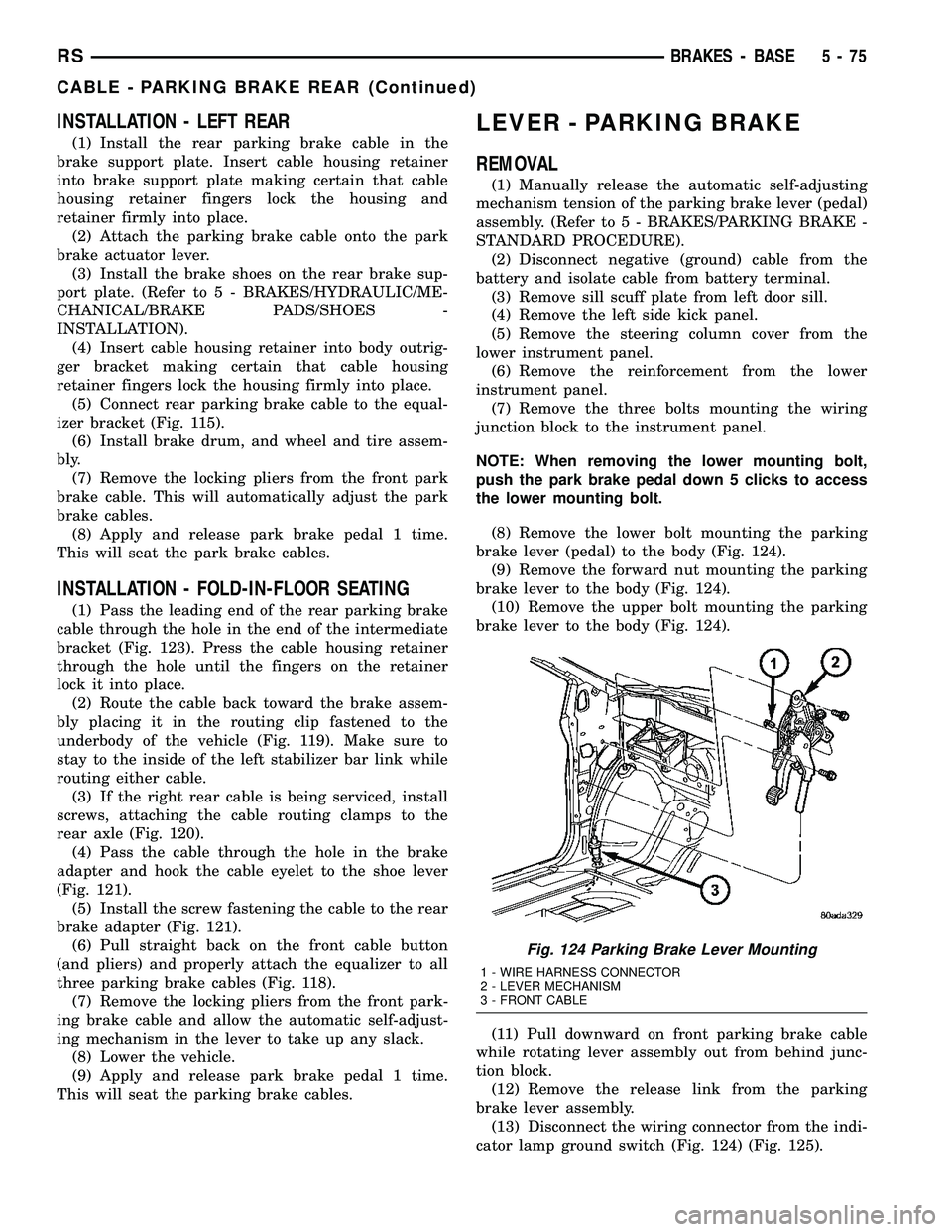
(8) Remove the lower bolt mounting the parking
brake lever (pedal) to the body (Fig. 124).
(9) Remove the forward nut mounting the parking
brake lever to the body (Fig. 124).
(10) Remove the upper bolt mounting the parking
brake lever to the body (Fig. 124).
(11) Pull downward on front parking brake cable
while rotating lever assembly out from behind junc-
tion block.
(12) Remove the release link from the parking
brake lever assembly.
(13) Disconnect the wiring connector from the indi-
cator lamp ground switch (Fig. 124) (Fig. 125).
Fig. 124 Parking Brake Lever Mounting
1 - WIRE HARNESS CONNECTOR
2 - LEVER MECHANISM
3 - FRONT CABLE
RSBRAKES - BASE5-75
CABLE - PARKING BRAKE REAR (Continued)