reset CHRYSLER VOYAGER 2005 Owner's Guide
[x] Cancel search | Manufacturer: CHRYSLER, Model Year: 2005, Model line: VOYAGER, Model: CHRYSLER VOYAGER 2005Pages: 2339, PDF Size: 59.69 MB
Page 466 of 2339

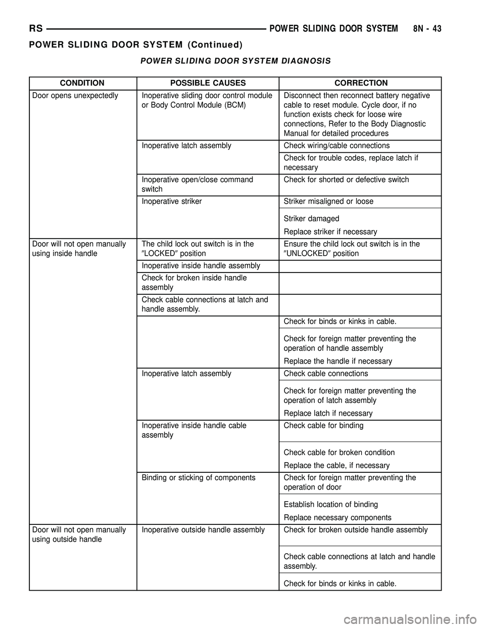
POWER SLIDING DOOR SYSTEM DIAGNOSIS
CONDITION POSSIBLE CAUSES CORRECTION
Door opens unexpectedly Inoperative sliding door control module
or Body Control Module (BCM)Disconnect then reconnect battery negative
cable to reset module. Cycle door, if no
function exists check for loose wire
connections, Refer to the Body Diagnostic
Manual for detailed procedures
Inoperative latch assembly Check wiring/cable connections
Check for trouble codes, replace latch if
necessary
Inoperative open/close command
switchCheck for shorted or defective switch
Inoperative striker Striker misaligned or loose
Striker damaged
Replace striker if necessary
Door will not open manually
using inside handleThe child lock out switch is in the
9LOCKED9positionEnsure the child lock out switch is in the
9UNLOCKED9position
Inoperative inside handle assembly
Check for broken inside handle
assembly
Check cable connections at latch and
handle assembly.
Check for binds or kinks in cable.
Check for foreign matter preventing the
operation of handle assembly
Replace the handle if necessary
Inoperative latch assembly Check cable connections
Check for foreign matter preventing the
operation of latch assembly
Replace latch if necessary
Inoperative inside handle cable
assemblyCheck cable for binding
Check cable for broken condition
Replace the cable, if necessary
Binding or sticking of components Check for foreign matter preventing the
operation of door
Establish location of binding
Replace necessary components
Door will not open manually
using outside handleInoperative outside handle assembly Check for broken outside handle assembly
Check cable connections at latch and handle
assembly.
Check for binds or kinks in cable.
RSPOWER SLIDING DOOR SYSTEM8N-43
POWER SLIDING DOOR SYSTEM (Continued)
Page 467 of 2339

CONDITION POSSIBLE CAUSES CORRECTION
Check for foreign matter preventing the
operation of handle assembly
Replace the handle if necessary
Inoperative latch assembly Check cable connections
Check for foreign matter preventing the
operation of latch assembly
Replace latch assembly, if necessary
Inoperative outside handle cable
assemblyCheck cable for binding
Check cable for broken condition
Replace the cable, if necessary
Binding or sticking of components Check for foreign matter preventing the
operation of door
Establish location of binding
Replace necessary components
Sliding door will not
open/close manuallyBinding or sticking of components Establish location of binding. Disconnect flex
drive and recheck. Replace necessary
components
Inoperative latch assembly Check cable connections
Check for foreign matter preventing the
operation of latch assembly
Replace latch assembly, if necessary
Sliding door will not
open/close under powerBinding or sticking of components Open and close door manually to assess
binding or high effort to move door. Establish
location of binding and replace necessary
components
Inoperative sliding door control module
or BCMDisconnect then reconnect battery negative
cable to reset module. Cycle door, if no
function exists check for loose wire
connections, see Body Diagnostic Manual for
detailed procedures
Inoperative latch assembly Check for blown fuse and wire connections
Check cable connections
Check for foreign matter preventing the
operation of latch assembly
Troubleshoot using body diagnostic manual
Replace latch assembly, if necessary
Inoperative motor assembly Troubleshoot using body diagnostic manual
Inoperative full open switch assembly Troubleshoot using body diagnostic manual
Inoperative flex drive assembly Disconnect flex drive and check for broken
condition
Inoperative lower drive unit assembly Remove lower drive unit and check for
broken condition
8N - 44 POWER SLIDING DOOR SYSTEMRS
POWER SLIDING DOOR SYSTEM (Continued)
Page 468 of 2339

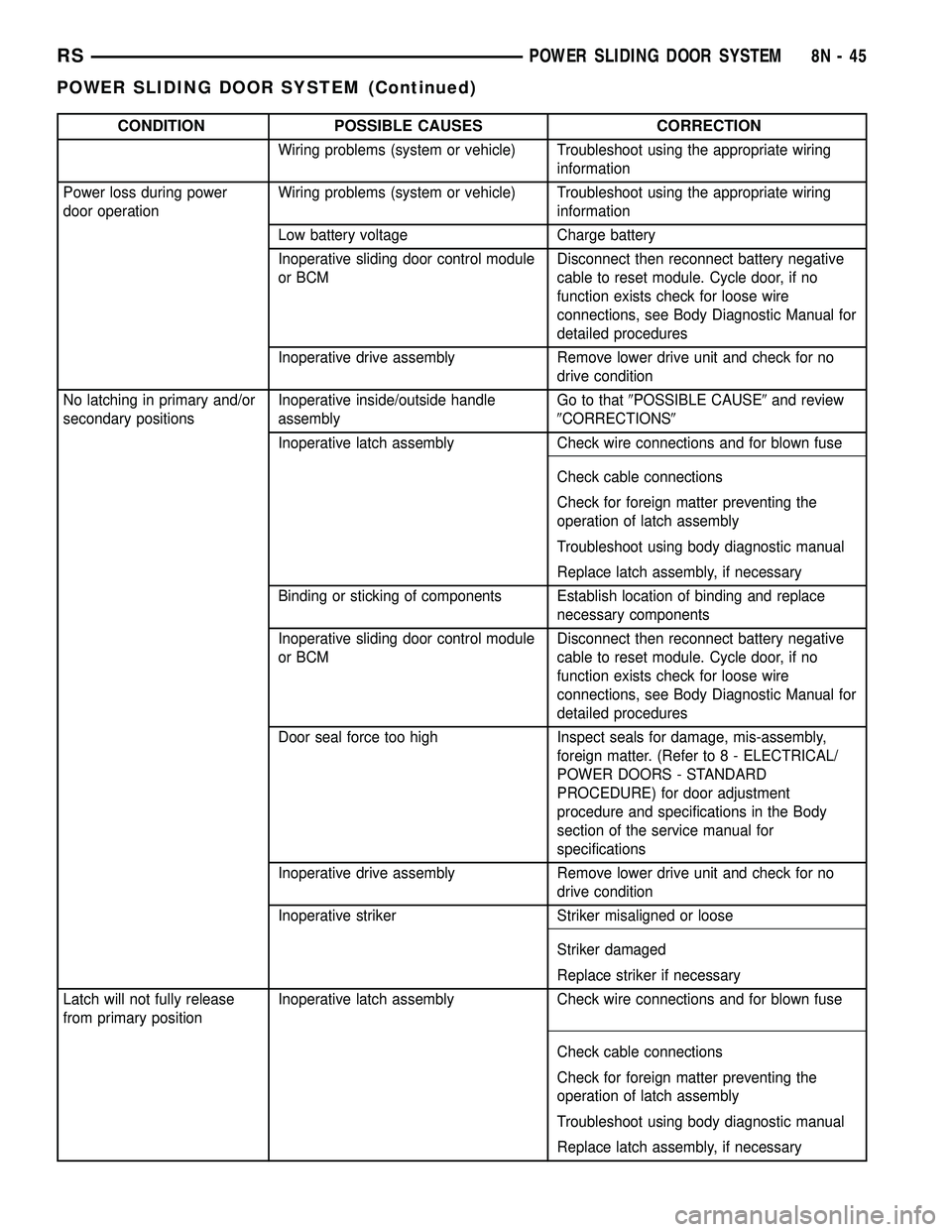
CONDITION POSSIBLE CAUSES CORRECTION
Wiring problems (system or vehicle) Troubleshoot using the appropriate wiring
information
Power loss during power
door operationWiring problems (system or vehicle) Troubleshoot using the appropriate wiring
information
Low battery voltage Charge battery
Inoperative sliding door control module
or BCMDisconnect then reconnect battery negative
cable to reset module. Cycle door, if no
function exists check for loose wire
connections, see Body Diagnostic Manual for
detailed procedures
Inoperative drive assembly Remove lower drive unit and check for no
drive condition
No latching in primary and/or
secondary positionsInoperative inside/outside handle
assemblyGo to that9POSSIBLE CAUSE9and review
9CORRECTIONS9
Inoperative latch assembly Check wire connections and for blown fuse
Check cable connections
Check for foreign matter preventing the
operation of latch assembly
Troubleshoot using body diagnostic manual
Replace latch assembly, if necessary
Binding or sticking of components Establish location of binding and replace
necessary components
Inoperative sliding door control module
or BCMDisconnect then reconnect battery negative
cable to reset module. Cycle door, if no
function exists check for loose wire
connections, see Body Diagnostic Manual for
detailed procedures
Door seal force too high Inspect seals for damage, mis-assembly,
foreign matter. (Refer to 8 - ELECTRICAL/
POWER DOORS - STANDARD
PROCEDURE) for door adjustment
procedure and specifications in the Body
section of the service manual for
specifications
Inoperative drive assembly Remove lower drive unit and check for no
drive condition
Inoperative striker Striker misaligned or loose
Striker damaged
Replace striker if necessary
Latch will not fully release
from primary positionInoperative latch assembly Check wire connections and for blown fuse
Check cable connections
Check for foreign matter preventing the
operation of latch assembly
Troubleshoot using body diagnostic manual
Replace latch assembly, if necessary
RSPOWER SLIDING DOOR SYSTEM8N-45
POWER SLIDING DOOR SYSTEM (Continued)
Page 469 of 2339

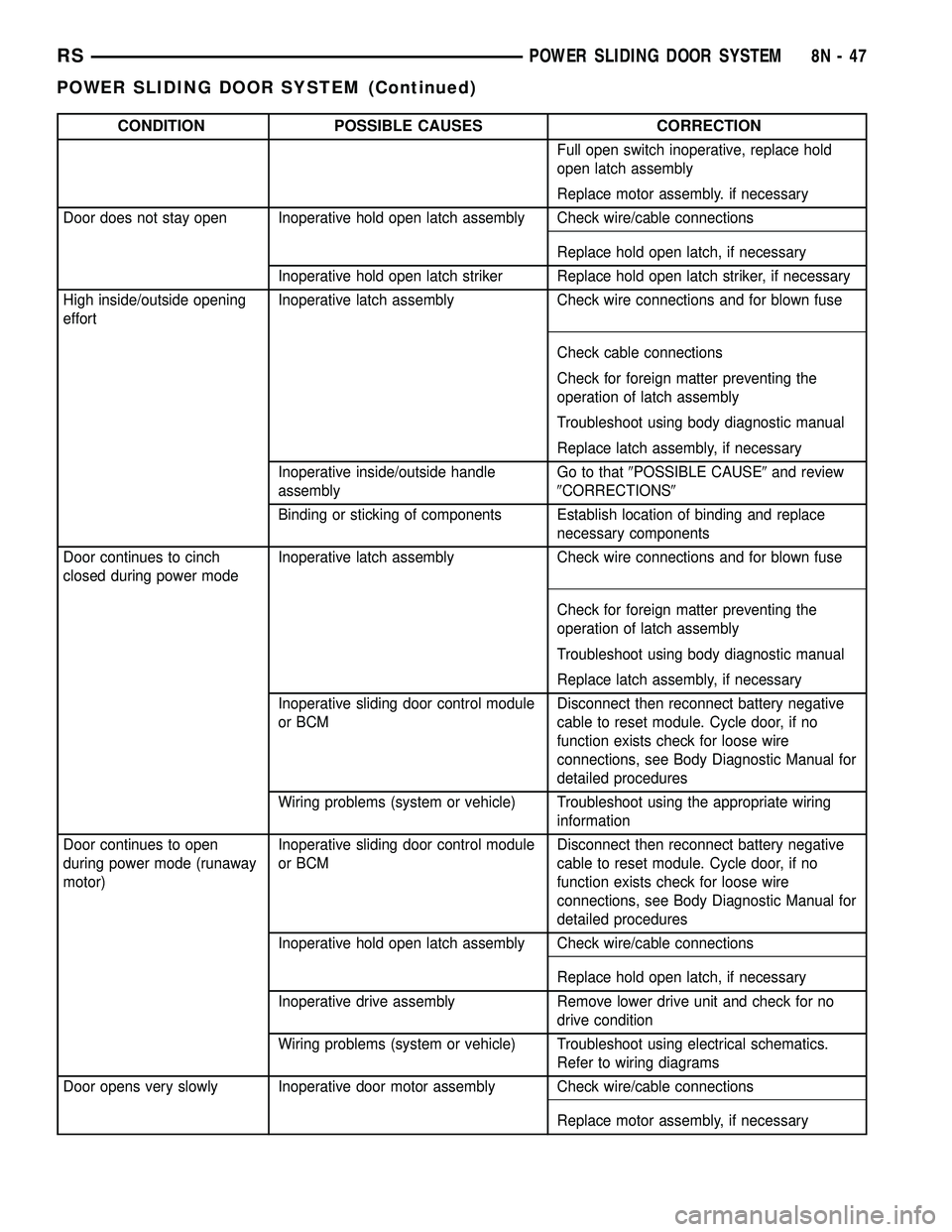
CONDITION POSSIBLE CAUSES CORRECTION
Inoperative fuel filler door lockout
mechanismCheck operation of fuel filler door lockout
mechanism.
Inoperative sliding door control module
or BCMDisconnect then reconnect battery negative
cable to reset module. Cycle door, if no
function exists check for loose wire
connections, see Body Diagnostic Manual for
detailed procedures
Inoperative striker Striker misaligned or loose
Striker damaged
Replace striker if necessary
Cables worn and stretched Replace cables as necessary
Binding or sticking of components Establish location of binding and replace
necessary components
Key fob, B-pillar or overhead
console switch does not
operate power sliding doorBlown Fuse Check fuse and replace
Battery voltage low Charge or replace battery
Inoperative latch assembly Check for foreign matter preventing the
operation of latch assembly
Check wire connection
Pawl and/or ratchet switch inoperative
Replace latch if necessary
Wiring problems (system or vehicle) Troubleshoot using the appropriate wiring
information
Inoperative BCM Check electrical connections
Refer to the body diagnostic manual for
additional checks
Replace BCM if necessary
Inoperative key fob Verify inoperative key fob by trying other key
fob functions
Replace key fob battery
Reprogram key fob
Replace key fob if necessary
Inoperative sliding door control module Disconnect then reconnect battery negative
cable to reset module. Cycle door, if no
function exists check for loose wire
connections, see Body Diagnostic Manual for
detailed procedures
Inoperative door motor assembly Check for foreign matter preventing the
operation of gear motor assembly
Check wire connections
Gear motor clutch does not engage, replace
assembly
8N - 46 POWER SLIDING DOOR SYSTEMRS
POWER SLIDING DOOR SYSTEM (Continued)
Page 470 of 2339

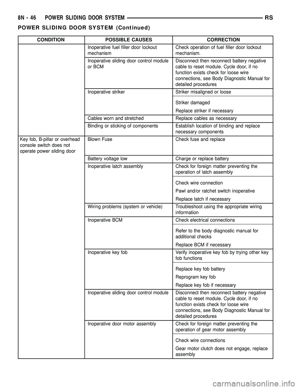
CONDITION POSSIBLE CAUSES CORRECTION
Full open switch inoperative, replace hold
open latch assembly
Replace motor assembly. if necessary
Door does not stay open Inoperative hold open latch assembly Check wire/cable connections
Replace hold open latch, if necessary
Inoperative hold open latch striker Replace hold open latch striker, if necessary
High inside/outside opening
effortInoperative latch assembly Check wire connections and for blown fuse
Check cable connections
Check for foreign matter preventing the
operation of latch assembly
Troubleshoot using body diagnostic manual
Replace latch assembly, if necessary
Inoperative inside/outside handle
assemblyGo to that9POSSIBLE CAUSE9and review
9CORRECTIONS9
Binding or sticking of components Establish location of binding and replace
necessary components
Door continues to cinch
closed during power modeInoperative latch assembly Check wire connections and for blown fuse
Check for foreign matter preventing the
operation of latch assembly
Troubleshoot using body diagnostic manual
Replace latch assembly, if necessary
Inoperative sliding door control module
or BCMDisconnect then reconnect battery negative
cable to reset module. Cycle door, if no
function exists check for loose wire
connections, see Body Diagnostic Manual for
detailed procedures
Wiring problems (system or vehicle) Troubleshoot using the appropriate wiring
information
Door continues to open
during power mode (runaway
motor)Inoperative sliding door control module
or BCMDisconnect then reconnect battery negative
cable to reset module. Cycle door, if no
function exists check for loose wire
connections, see Body Diagnostic Manual for
detailed procedures
Inoperative hold open latch assembly Check wire/cable connections
Replace hold open latch, if necessary
Inoperative drive assembly Remove lower drive unit and check for no
drive condition
Wiring problems (system or vehicle) Troubleshoot using electrical schematics.
Refer to wiring diagrams
Door opens very slowly Inoperative door motor assembly Check wire/cable connections
Replace motor assembly, if necessary
RSPOWER SLIDING DOOR SYSTEM8N-47
POWER SLIDING DOOR SYSTEM (Continued)
Page 1174 of 2339

8W-97 POWER DISTRIBUTION SYSTEM
TABLE OF CONTENTS
page page
POWER DISTRIBUTION SYSTEM
DESCRIPTION..........................1
OPERATION............................1
SPECIAL TOOLS
POWER DISTRIBUTION SYSTEMS.........1
INTEGRATED POWER MODULE
DESCRIPTION..........................1
OPERATION............................2
REMOVAL.............................2
INSTALLATION..........................2IOD FUSE
DESCRIPTION..........................3
OPERATION............................3
POWER OUTLET
DESCRIPTION..........................3
OPERATION............................3
DIAGNOSIS AND TESTING
DIAGNOSIS & TESTING - POWER OUTLET . . 3
REMOVAL.............................4
INSTALLATION..........................4
POWER DISTRIBUTION
SYSTEM
DESCRIPTION
The power distribution system for this vehicle con-
sists of the following components:
²Integrated Power Module (IPM)
²Front Control Module (FCM)
²Power Outlets
Refer to Wiring Diagrams for complete circuit sche-
matics.
The power distribution system also incorporates
various types of circuit control and protection fea-
tures, including:
²Automatic resetting circuit breakers
²Blade-type fuses
²Bus bars
²Cartridge fuses
²Circuit splice blocks
²Flashers
²Fusible links
²Relays
OPERATION
The power distribution system for this vehicle is
designed to provide safe, reliable, and centralized dis-
tribution points for the electrical current required to
operate all of the many standard and optional facto-
ry-installed electrical and electronic powertrain,
chassis, safety, security, comfort and convenience sys-
tems. At the same time, the power distribution sys-
tem was designed to provide ready access to these
electrical distribution points for the vehicle techni-
cian to use when conducting diagnosis and repair of
faulty circuits. The power distribution system can
also prove useful for the sourcing of additional elec-
trical circuits that may be required to provide theelectrical current needed to operate many accessories
that the vehicle owner may choose to have installed.
SPECIAL TOOLS
POWER DISTRIBUTION SYSTEMS
INTEGRATED POWER MODULE
DESCRIPTION
The Integrated Power Module (IPM) is a combina-
tion of the Power Distribution Center (PDC) and the
Front Control Module (FCM). The IPM is located in
the engine compartment, next to the battery. (Fig. 1).
The PDC mates directly with the FCM to form the
IPM. The PDC is a printed circuit board based mod-
ule that contains fuses and relays, while the FCM
contains the electronics controlling the IPM and
other functions. This IPM connects directly to the
battery positive through a four pin connector. The
ground connection is through two other connectors.
Terminal Pick Kit 6680
RS8W-97 POWER DISTRIBUTION SYSTEM8W-97-1
Page 1387 of 2339

FUEL INJECTION
OPERATION
OPERATION - INJECTION SYSTEM
All engines used in this section have a sequential
Multi-Port Electronic Fuel Injection system. The MPI
system is computer regulated and provides precise
air/fuel ratios for all driving conditions. The Power-
train Control Module (PCM) operates the fuel injec-
tion system.
The PCM regulates:
²Ignition timing
²Air/fuel ratio
²Emission control devices
²Cooling fan
²Charging system
²Idle speed
²Vehicle speed control
Various sensors provide the inputs necessary for
the PCM to correctly operate these systems. In addi-
tion to the sensors, various switches also provide
inputs to the PCM.
The PCM can adapt its programming to meet
changing operating conditions.
Fuel is injected into the intake port above the
intake valve in precise metered amounts through
electrically operated injectors. The PCM fires the
injectors in a specific sequence. Under most operat-
ing conditions, the PCM maintains an air fuel ratio
of 14.7 parts air to 1 part fuel by constantly adjust-
ing injector pulse width. Injector pulse width is the
length of time the injector is open.
The PCM adjusts injector pulse width by opening
and closing the ground path to the injector. Engine
RPM (speed) and manifold absolute pressure (air
density) are theprimaryinputs that determine
injector pulse width.
OPERATION - MODES OF OPERATION
As input signals to the PCM change, the PCM
adjusts its response to output devices. For example,
the PCM must calculate a different injector pulse
width and ignition timing for idle than it does for
Wide Open Throttle (WOT). There are several differ-
ent modes of operation that determine how the PCM
responds to the various input signals.
There are two different areas of operation, OPEN
LOOP and CLOSED LOOP.
During OPEN LOOP modes the PCM receives
input signals and responds according to preset PCM
programming. Inputs from the upstream and down-
stream heated oxygen sensors are not monitored dur-
ing OPEN LOOP modes, except for heated oxygensensor diagnostics (they are checked for shorted con-
ditions at all times).
During CLOSED LOOP modes the PCM monitors
the inputs from the upstream and downstream
heated oxygen sensors. The upstream heated oxygen
sensor input tells the PCM if the calculated injector
pulse width resulted in the ideal air-fuel ratio of 14.7
to one. By monitoring the exhaust oxygen content
through the upstream heated oxygen sensor, the
PCM can fine tune injector pulse width. Fine tuning
injector pulse width allows the PCM to achieve opti-
mum fuel economy combined with low emissions.
For the PCM to enter CLOSED LOOP operation,
the following must occur:
(1) Engine coolant temperature must be over 35ÉF.
²If the coolant is over 35ÉF the PCM will wait 38
seconds.
²If the coolant is over 50ÉF the PCM will wait 15
seconds.
²If the coolant is over 167ÉF the PCM will wait 3
seconds.
(2) For other temperatures the PCM will interpo-
late the correct waiting time.
(3) O2 sensor must read either greater than 0.745
volts or less than 0.29 volt.
(4) The multi-port fuel injection systems has the
following modes of operation:
²Ignition switch ON (Zero RPM)
²Engine start-up
²Engine warm-up
²Cruise
²Idle
²Acceleration
²Deceleration
²Wide Open Throttle
²Ignition switch OFF
(5) The engine start-up (crank), engine warm-up,
deceleration with fuel shutoff and wide open throttle
modes are OPEN LOOP modes. Under most operat-
ing conditions, the acceleration, deceleration (with
A/C on), idle and cruise modes,with the engine at
operating temperatureare CLOSED LOOP modes.
IGNITION SWITCH ON (ZERO RPM) MODE
When the ignition switch activates the fuel injec-
tion system, the following actions occur:
²The PCM monitors the engine coolant tempera-
ture sensor and throttle position sensor input. The
PCM determines basic fuel injector pulse width from
this input.
²The PCM determines atmospheric air pressure
from the MAP sensor input to modify injector pulse
width.
When the key is in the ON position and the engine
is not running (zero rpm), the Auto Shutdown (ASD)
and fuel pump relays de-energize after approximately
14 - 22 FUEL INJECTIONRS
Page 1389 of 2339

²All monitored components (refer to the Emission
section for On-Board Diagnostics).
The PCM compares the upstream and downstream
heated oxygen sensor inputs to measure catalytic
convertor efficiency. If the catalyst efficiency drops
below the minimum acceptable percentage, the PCM
stores a diagnostic trouble code in memory, after 2
trips.
During certain idle conditions, the PCM may enter
a variable idle speed strategy. During variable idle
speed strategy the PCM adjusts engine speed based
on the following inputs.
²A/C status
²Battery voltage
²Battery temperature or Calculated Battery Tem-
perature
²Engine coolant temperature
²Engine run time
²Inlet/Intake air temperature
²Vehicle mileage
ACCELERATION MODE
This is a CLOSED LOOP mode. The PCM recog-
nizes an abrupt increase in Throttle Position sensor
output voltage or MAP sensor output voltage as a
demand for increased engine output and vehicle
acceleration. The PCM increases injector pulse width
in response to increased fuel demand.
²Wide Open Throttle-open loop
DECELERATION MODE
This is a CLOSED LOOP mode. During decelera-
tion the following inputs are received by the PCM:
²A/C status
²Battery voltage
²Inlet/Intake air temperature
²Engine coolant temperature
²Crankshaft position (engine speed)
²Exhaust gas oxygen content (upstream heated
oxygen sensor)
²Knock sensor
²Manifold absolute pressure
²Throttle position sensor
²IAC motor (solenoid) control changes in response
to MAP sensor feedback
The PCM may receive a closed throttle input from
the Throttle Position Sensor (TPS) when it senses an
abrupt decrease in manifold pressure. This indicates
a hard deceleration (Open Loop). In response, the
PCM may momentarily turn off the injectors. This
helps improve fuel economy, emissions and engine
braking.
WIDE-OPEN-THROTTLE MODE
This is an OPEN LOOP mode. During wide-open-
throttle operation, the following inputs are used by
the PCM:
²Inlet/Intake air temperature
²Engine coolant temperature
²Engine speed
²Knock sensor
²Manifold absolute pressure
²Throttle position
When the PCM senses a wide-open-throttle condi-
tion through the Throttle Position Sensor (TPS) it de-
energizes the A/C compressor clutch relay. This
disables the air conditioning system and disables
EGR (if equipped).
The PCM adjusts injector pulse width to supply a
predetermined amount of additional fuel, based on
MAP and RPM.
IGNITION SWITCH OFF MODE
When the operator turns the ignition switch to the
OFF position, the following occurs:
²All outputs are turned off, unless 02 Heater
Monitor test is being run. Refer to the Emission sec-
tion for On-Board Diagnostics.
²No inputs are monitored except for the heated
oxygen sensors. The PCM monitors the heating ele-
ments in the oxygen sensors and then shuts down.
FUEL CORRECTION or ADAPTIVE MEMORIES
DESCRIPTION
In Open Loop, the PCM changes pulse width with-
out feedback from the O2 Sensors. Once the engine
warms up to approximately 30 to 35É F, the PCM
goes into closed loopShort Term Correctionand
utilizes feedback from the O2 Sensors. Closed loop
Long Term Adaptive Memoryis maintained above
170É to 190É F unless the PCM senses wide open
throttle. At that time the PCM returns to Open Loop
operation.
OPERATION
Short Term
The first fuel correction program that begins func-
tioning is the short term fuel correction. This system
corrects fuel delivery in direct proportion to the read-
ings from the Upstream O2 Sensor.
The PCM monitors the air/fuel ratio by using the
input voltage from the O2 Sensor. When the voltage
reaches its preset high or low limit, the PCM begins
to add or remove fuel until the sensor reaches its
switch point. The short term corrections then begin.
The PCM makes a series of quick changes in the
injector pulse-width until the O2 Sensor reaches its
14 - 24 FUEL INJECTIONRS
FUEL INJECTION (Continued)
Page 1390 of 2339

opposite preset limit or switch point. The process
then repeats itself in the opposite direction.
Short term fuel correction will keep increasing or
decreasing injector pulse-width based upon the
upstream O2 Sensor input. The maximum range of
authority for short term memory is 25% (+/-) of base
pulse-width. Short term is violated and is lost when
ignition is turned OFF.
Long Term
The second fuel correction program is the long
term adaptive memory. In order to maintain correct
emission throughout all operating ranges of the
engine, a cell structure based on engine rpm and load
(MAP) is used.
Ther number of cells varies upon the driving con-
ditions. Two cells are used only during idle, based
upon TPS and Park/Neutral switch inputs. There
may be two other cells used for deceleration, based
on TPS, engine rpm, and vehicle speed. The other
twelve cells represent a manifold pressure and an
rpm range. Six of the cells are high rpm and the
other six are low rpm. Each of these cells has a spe-
cific MAP voltage range Typical Adaptive Memory
Fuel Cells.As the engine enters one of these cells the PCM
looks at the amount of short term correction being
used. Because the goal is to keep short term at 0 (O2
Sensor switching at 0.5 volt), long term will update
in the same direction as short term correction was
moving to bring the short term back to 0. Once short
term is back at 0, this long term correction factor is
stored in memory.
The values stored in long term adaptive memory
are used for all operating conditions, including open
loop and cold starting. However, the updating of the
long term memory occurs after the engine has
exceeded approximately 170É-190É F, with fuel control
in closed loop and two minutes of engine run time.
This is done to prevent any transitional temperature
or start-up compensations from corrupting long term
fuel correction.
Long term adaptive memory can change the pulse-
width by as much as 25%, which means it can correct
for all of short term. It is possible to have a problem
that would drive long term to 25% and short term to
another 25% for a total change of 50% away from
base pulse-width calculation.
TYPICAL ADAPTIVE MEMORY FUEL CELLS
Open
ThrottleOpen
ThrottleOpen
ThrottleOpen
ThrottleOpen
ThrottleOpen
Throttle Idle Decel
Vacuum 20 17 13 9 5 0
Above 1,984
rpm1 3 5 7 9 11 13 Drive 15
Below 1,984
rpm02 4 6 8 1012
Neutral14
MAP volt =0 1.4 2.0 2.6 3.3 3.9
Fuel Correction Diagnostics
There are two fuel correction diagnostic routines:
²Fuel System Rich
²Fuel System Lean
A DTC is set and the MIL is illuminated if the
PCM detects either of these conditions. This is deter-
mined based on total fuel correction, short term
times long term.
PROGRAMMABLE COMMUNICATIONS
INTERFACE (PCI) BUS
DESCRIPTION
The Programmable Communication Interface Mul-
tiplex system (PCI Bus) consist of a single wire. The
Body Control Module (BCM) acts as a splice to con-nect each module and the Data Link Connector
(DLC) together. Each module is wired in parallel to
the data bus through its PCI chip set and uses its
ground as the bus reference. The wiring is a mini-
mum 20 gage wire.
OPERATION
Various modules exchange information through a
communications port called the PCI Bus. The Power-
train Control Module (PCM) transmits the Malfunc-
tion Indicator Lamp (Check Engine) On/Off signal
and engine RPM on the PCI Bus. The PCM receives
the Air Conditioning select input, transaxle gear
position inputs over the PCI Bus. The PCM also
receives the air conditioning evaporator temperature
signal from the PCI Bus.
RSFUEL INJECTION14-25
FUEL INJECTION (Continued)
Page 1591 of 2339

TRANSMISSION CONTROL
RELAY
DESCRIPTION
The transmission control relay (Fig. 306) is located
in the Intelligent Power Module (IPM), which is
located on the left side of the engine compartment
between the battery and left fender.
OPERATION
The relay is supplied fused B+ voltage, energized by
the PCM/TCM, and is used to supply power to the sole-
noid pack when the transmission is in normal operating
mode. When the relay is ªoffº, no power is supplied to
the solenoid pack and the transmission is in ªlimp-inº
mode. After a controller reset (ignition key turned to the
ªrunº position or after cranking engine), the PCM/TCM
energizes the relay. Prior to this, the PCM/TCM verifies
that the contacts are open by checking for no voltage at
the switched battery terminals. After this is verified,
the voltage at the solenoid pack pressure switches is
checked. After the relay is energized, the PCM/TCM
monitors the terminals to verify that the voltage is
greater than 3 volts.
TRANSMISSION RANGE
SENSOR
DESCRIPTION
The Transmission Range Sensor (TRS) is mounted
to the top of the valve body inside the transaxle andcan only be serviced by removing the valve body. The
electrical connector extends through the transaxle
case (Fig. 307).
The Transmission Range Sensor (TRS) has four
switch contacts that monitor shift lever position and
send the information to the PCM/TCM.
The TRS also has an integrated temperature sen-
sor (thermistor) that communicates transaxle tem-
perature to the TCM and PCM (Fig. 308).
Fig. 306 Transmission Control Relay Location
1 - TRANSMISSION CONTROL RELAY
2 - LEFT FENDER
3 - INTELLIGENT POWER MODULE (IPM)
4 - BATTERY
Fig. 307 Transmission Range Sensor (TRS)
Location
1 - TRANSMISSION RANGE SENSOR
Fig. 308 Transmission Temperature Sensor
1 - TRANSMISSION RANGE SENSOR
2 - TEMPERATURE SENSOR
21 - 130 40TE AUTOMATIC TRANSAXLERS