service CHRYSLER VOYAGER 2005 Owner's Guide
[x] Cancel search | Manufacturer: CHRYSLER, Model Year: 2005, Model line: VOYAGER, Model: CHRYSLER VOYAGER 2005Pages: 2339, PDF Size: 59.69 MB
Page 71 of 2339
(9) Tighten nut (Fig. 5), removing bushing from
spring eye.
(10) Remove the tool from spring, then remove
bushing from tool.
INSTALLATION
(1) Install by hand NEW bushing in left side of
leaf spring eye.
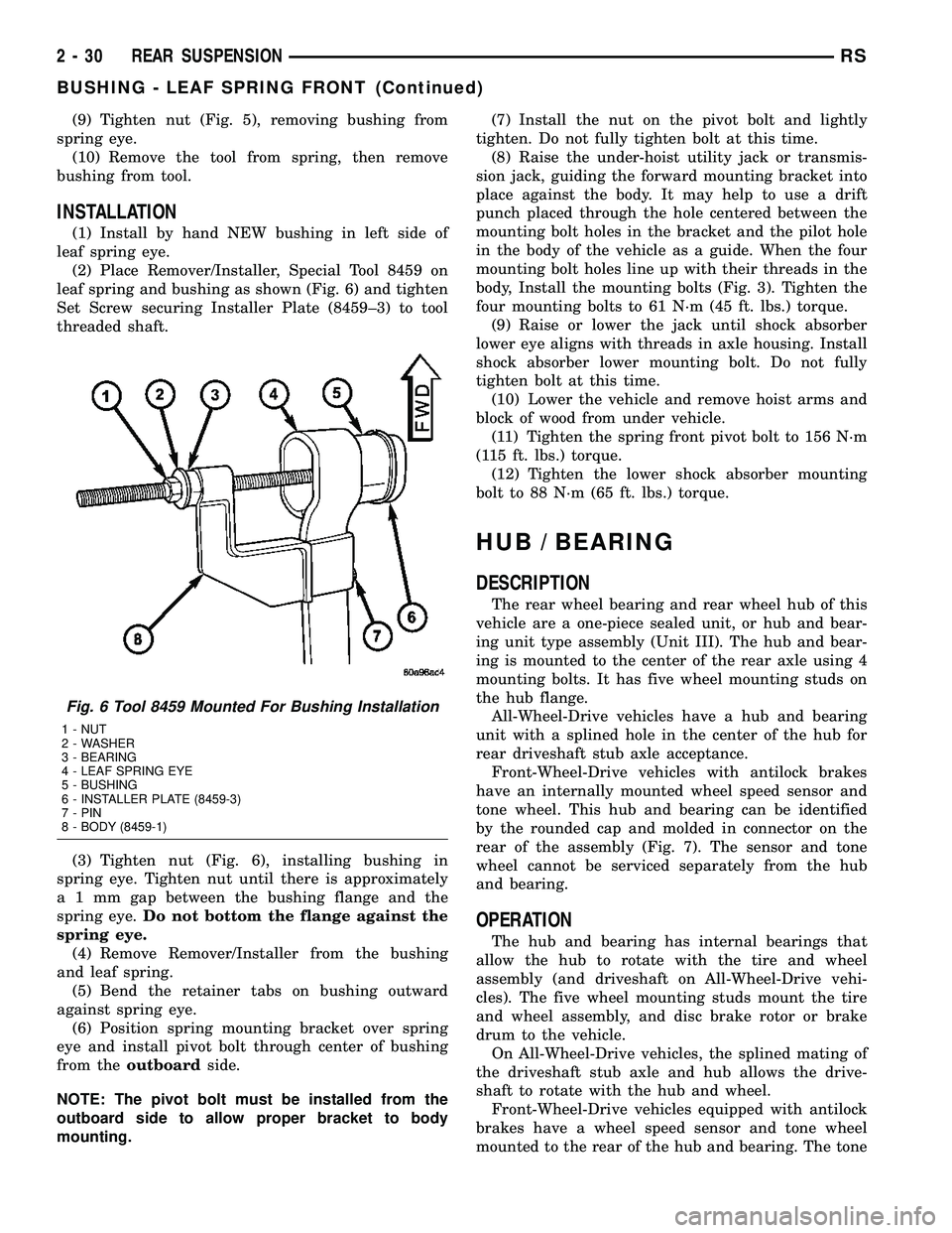
(2) Place Remover/Installer, Special Tool 8459 on
leaf spring and bushing as shown (Fig. 6) and tighten
Set Screw securing Installer Plate (8459±3) to tool
threaded shaft.
(3) Tighten nut (Fig. 6), installing bushing in
spring eye. Tighten nut until there is approximately
a 1 mm gap between the bushing flange and the
spring eye.Do not bottom the flange against the
spring eye.
(4) Remove Remover/Installer from the bushing
and leaf spring.
(5) Bend the retainer tabs on bushing outward
against spring eye.
(6) Position spring mounting bracket over spring
eye and install pivot bolt through center of bushing
from theoutboardside.
NOTE: The pivot bolt must be installed from the
outboard side to allow proper bracket to body
mounting.(7) Install the nut on the pivot bolt and lightly
tighten. Do not fully tighten bolt at this time.
(8) Raise the under-hoist utility jack or transmis-
sion jack, guiding the forward mounting bracket into
place against the body. It may help to use a drift
punch placed through the hole centered between the
mounting bolt holes in the bracket and the pilot hole
in the body of the vehicle as a guide. When the four
mounting bolt holes line up with their threads in the
body, Install the mounting bolts (Fig. 3). Tighten the
four mounting bolts to 61 N´m (45 ft. lbs.) torque.
(9) Raise or lower the jack until shock absorber
lower eye aligns with threads in axle housing. Install
shock absorber lower mounting bolt. Do not fully
tighten bolt at this time.
(10) Lower the vehicle and remove hoist arms and
block of wood from under vehicle.
(11) Tighten the spring front pivot bolt to 156 N´m
(115 ft. lbs.) torque.
(12) Tighten the lower shock absorber mounting
bolt to 88 N´m (65 ft. lbs.) torque.
HUB / BEARING
DESCRIPTION
The rear wheel bearing and rear wheel hub of this
vehicle are a one-piece sealed unit, or hub and bear-
ing unit type assembly (Unit III). The hub and bear-
ing is mounted to the center of the rear axle using 4
mounting bolts. It has five wheel mounting studs on
the hub flange.
All-Wheel-Drive vehicles have a hub and bearing
unit with a splined hole in the center of the hub for
rear driveshaft stub axle acceptance.
Front-Wheel-Drive vehicles with antilock brakes
have an internally mounted wheel speed sensor and
tone wheel. This hub and bearing can be identified
by the rounded cap and molded in connector on the
rear of the assembly (Fig. 7). The sensor and tone
wheel cannot be serviced separately from the hub
and bearing.
OPERATION
The hub and bearing has internal bearings that
allow the hub to rotate with the tire and wheel
assembly (and driveshaft on All-Wheel-Drive vehi-
cles). The five wheel mounting studs mount the tire
and wheel assembly, and disc brake rotor or brake
drum to the vehicle.
On All-Wheel-Drive vehicles, the splined mating of
the driveshaft stub axle and hub allows the drive-
shaft to rotate with the hub and wheel.
Front-Wheel-Drive vehicles equipped with antilock
brakes have a wheel speed sensor and tone wheel
mounted to the rear of the hub and bearing. The tone
Fig. 6 Tool 8459 Mounted For Bushing Installation
1 - NUT
2 - WASHER
3 - BEARING
4 - LEAF SPRING EYE
5 - BUSHING
6 - INSTALLER PLATE (8459-3)
7 - PIN
8 - BODY (8459-1)
2 - 30 REAR SUSPENSIONRS
BUSHING - LEAF SPRING FRONT (Continued)
Page 79 of 2339
(6) Install the shock absorber on the vehicle. Refer
to REMOVAL AND INSTALLATION in this section
for the procedure.
INSTALLATION - SHOCK ABSORBER
(1) While holding shock absorber in position
against the frame rail, install the shock absorber
upper mounting bolt.
(2) Install the shock absorber lower mounting bolt
securing the lower end of the shock absorber to the
axle.
(3) Remove the support jack.
(4) Lower the vehicle to the ground so the full curb
weight of the vehicle is supported by the suspension.
(5) Tighten the upper and lower shock absorber
mounting bolt to a torque of 88 N´m (65 ft. lbs.).
SPRING - AWD
REMOVAL
(1) Raise vehicle on frame-contact hoist as follows:
(a) Position the hoist arm supporting the corner
of the vehicle to be serviced against a block of wood
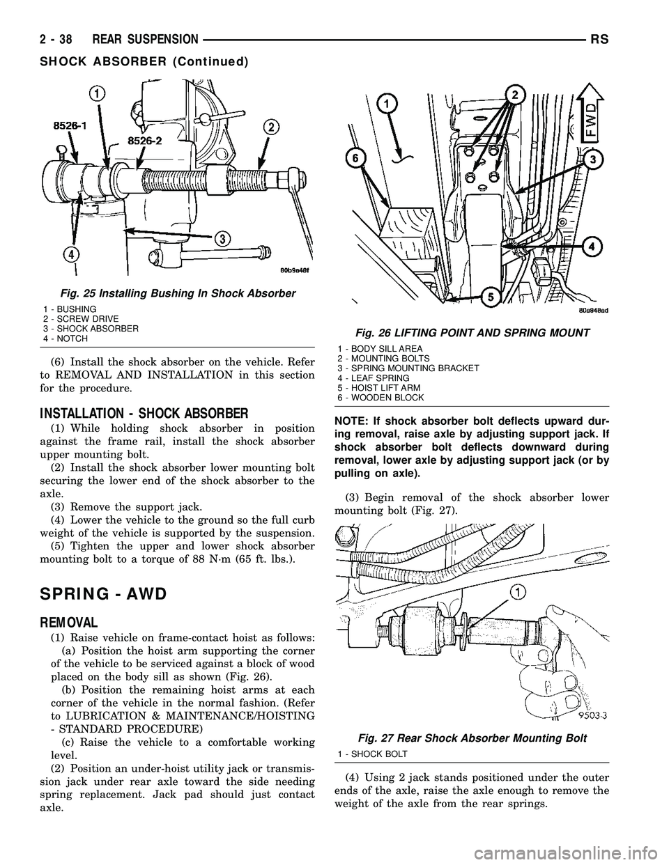
placed on the body sill as shown (Fig. 26).
(b) Position the remaining hoist arms at each
corner of the vehicle in the normal fashion. (Refer
to LUBRICATION & MAINTENANCE/HOISTING
- STANDARD PROCEDURE)
(c) Raise the vehicle to a comfortable working
level.
(2) Position an under-hoist utility jack or transmis-
sion jack under rear axle toward the side needing
spring replacement. Jack pad should just contact
axle.NOTE: If shock absorber bolt deflects upward dur-
ing removal, raise axle by adjusting support jack. If
shock absorber bolt deflects downward during
removal, lower axle by adjusting support jack (or by
pulling on axle).
(3) Begin removal of the shock absorber lower
mounting bolt (Fig. 27).
(4) Using 2 jack stands positioned under the outer
ends of the axle, raise the axle enough to remove the
weight of the axle from the rear springs.
Fig. 25 Installing Bushing In Shock Absorber
1 - BUSHING
2 - SCREW DRIVE
3 - SHOCK ABSORBER
4 - NOTCH
Fig. 26 LIFTING POINT AND SPRING MOUNT
1 - BODY SILL AREA
2 - MOUNTING BOLTS
3 - SPRING MOUNTING BRACKET
4 - LEAF SPRING
5 - HOIST LIFT ARM
6 - WOODEN BLOCK
Fig. 27 Rear Shock Absorber Mounting Bolt
1 - SHOCK BOLT
2 - 38 REAR SUSPENSIONRS
SHOCK ABSORBER (Continued)
Page 81 of 2339
CAUTION: The following sequence must be fol-
lowed when tightening the pin nuts on the rear
hanger for the rear leaf spring. First the hanger pin
nuts must be tightened to the specified torque
shown below. Then tighten the retaining bolts for
the inner to outer half of the spring hanger to the
torque specification listed below. This sequence
must be followed to properly seat the bushings into
the springs and to avoid bending the spring hanger.
(8) Tighten the spring front pivot bolt to 156 N´m
(115 ft. lbs.) torque.
(9) Tighten rear spring shackle pin nuts to 61 N´m
(45 ft. lbs.) torque.
(10) Tighten rear spring shackle inner to outer
half retaining bolts to 61 N´m (45 ft. lbs.) torque.
(11) Tighten the lower shock absorber mounting
bolt to 102 N´m (75 ft. lbs.) torque.
SPRING - CARGO
REMOVAL
(1) Raise vehicle on frame-contact hoist as follows:
(a) Position the hoist arm supporting the corner
of the vehicle to be serviced against a block of wood
placed on the body sill as shown (Fig. 26).
(b) Position the remaining hoist arms at each
corner of the vehicle in the normal fashion. (Refer
to LUBRICATION & MAINTENANCE/HOISTING
- STANDARD PROCEDURE)
(c) Raise the vehicle to a comfortable working
level.
(2) Position an under-hoist utility jack or transmis-
sion jack under rear axle toward the side needing
spring replacement. Jack pad should just contact
axle.
NOTE: If shock absorber bolt deflects upward dur-
ing removal, raise axle by adjusting support jack. If
shock absorber bolt deflects downward during
removal, lower axle by adjusting support jack (or by
pulling on axle).
(3) Begin removal of the shock absorber lower
mounting bolt (Fig. 27).
(4) Using 2 jack stands positioned under the outer
ends of the axle, raise the axle enough to remove the
weight of the axle from the rear springs.
(5) Loosen and remove the axle plate bolts from
the rear axle (Fig. 28).
(6) Using the jack standsslowlylower the rear
axle, permitting the rear springs to hang free.
(7) Loosen and remove the 4 bolts at the front
mount of the rear leaf spring (Fig. 26).
(8) Loosen and remove the nuts from the spring
hanger for the rear leaf spring (Fig. 35).(9) Remove the hanger plate from the hanger and
remove the spring from the spring hanger (Fig. 35).
(10) Remove the leaf spring from the vehicle.
(11) Loosen and remove the pivot bolt from the
front mount of the rear leaf spring. (Fig. 30).
INSTALLATION
CAUTION: Pivot bolt must face inboard to prevent
structural damage during installation of spring.
(1) Install the front eyelet of the rear leaf spring
into the spring mount. Install the pivot bolt and nut.
Do not tighten the pivot bolt at this time.
(2) Position the front spring mount for the rear
leaf spring against the floor pan of the vehicle.
Install the 4 mounting bolts for the front spring
mount (Fig. 26). Tighten the 4 mounting bolts to a
torque of 61 N´m (45 ft. lbs.).
(3) Install rear of spring onto rear spring shackle.
Install shackle plate and nuts (Fig. 35).Do not
tighten at this time.
(4) Raise axle assembly into correct position with
axle centered under spring locator post.
(5) Install axle plate bolts (Fig. 28). Tighten bolts
to 95 N´m (70 ft. lbs.) torque.
(6) Install shock absorber bolts.Do not tighten
at this time.
(7) Lower the vehicle and remove hoist arms and
block of wood from under vehicle.
CAUTION: The following sequence must be fol-
lowed when tightening the pin nuts on the rear
hanger for the rear leaf spring. First the hanger pin
nuts must be tightened to the specified torque
shown below. Then tighten the retaining bolts for
the inner to outer half of the spring hanger to the
torque specification listed below. This sequence
must be followed to properly seat the bushings into
the springs and to avoid bending the spring hanger.
(8) Tighten the spring front pivot bolt to 156 N´m
(115 ft. lbs.) torque.
(9) Tighten rear spring shackle pin nuts to 61 N´m
(45 ft. lbs.) torque.
(10) Tighten the lower shock absorber mounting
bolt to 102 N´m (75 ft. lbs.) torque.
SPRING - FWD
REMOVAL
(1) Raise vehicle on frame-contact hoist as follows:
(a) Position the hoist arm supporting the corner
of the vehicle to be serviced against a block of wood
placed on the body sill as shown (Fig. 31).
2 - 40 REAR SUSPENSIONRS
SPRING - AWD (Continued)
Page 83 of 2339
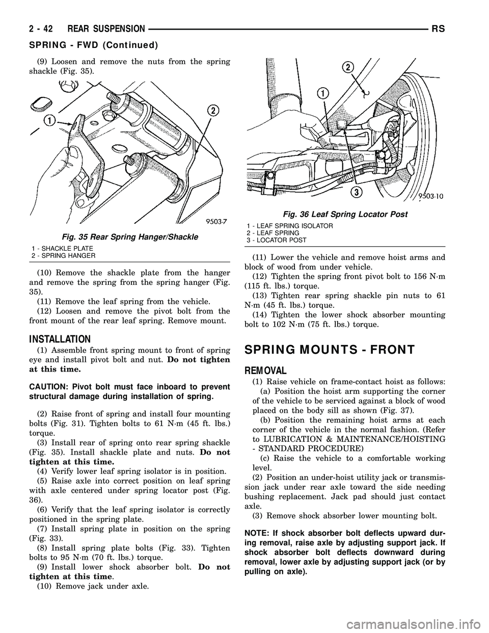
(9) Loosen and remove the nuts from the spring
shackle (Fig. 35).
(10) Remove the shackle plate from the hanger
and remove the spring from the spring hanger (Fig.
35).
(11) Remove the leaf spring from the vehicle.
(12) Loosen and remove the pivot bolt from the
front mount of the rear leaf spring. Remove mount.
INSTALLATION
(1) Assemble front spring mount to front of spring
eye and install pivot bolt and nut.Do not tighten
at this time.
CAUTION: Pivot bolt must face inboard to prevent
structural damage during installation of spring.
(2) Raise front of spring and install four mounting
bolts (Fig. 31). Tighten bolts to 61 N´m (45 ft. lbs.)
torque.
(3) Install rear of spring onto rear spring shackle
(Fig. 35). Install shackle plate and nuts.Do not
tighten at this time.
(4) Verify lower leaf spring isolator is in position.
(5) Raise axle into correct position on leaf spring
with axle centered under spring locator post (Fig.
36).
(6) Verify that the leaf spring isolator is correctly
positioned in the spring plate.
(7) Install spring plate in position on the spring
(Fig. 33).
(8) Install spring plate bolts (Fig. 33). Tighten
bolts to 95 N´m (70 ft. lbs.) torque.
(9) Install lower shock absorber bolt.Do not
tighten at this time.
(10) Remove jack under axle.(11) Lower the vehicle and remove hoist arms and
block of wood from under vehicle.
(12) Tighten the spring front pivot bolt to 156 N´m
(115 ft. lbs.) torque.
(13) Tighten rear spring shackle pin nuts to 61
N´m (45 ft. lbs.) torque.
(14) Tighten the lower shock absorber mounting
bolt to 102 N´m (75 ft. lbs.) torque.SPRING MOUNTS - FRONT
REMOVAL
(1) Raise vehicle on frame-contact hoist as follows:
(a) Position the hoist arm supporting the corner
of the vehicle to be serviced against a block of wood
placed on the body sill as shown (Fig. 37).
(b) Position the remaining hoist arms at each
corner of the vehicle in the normal fashion. (Refer
to LUBRICATION & MAINTENANCE/HOISTING
- STANDARD PROCEDURE)
(c) Raise the vehicle to a comfortable working
level.
(2) Position an under-hoist utility jack or transmis-
sion jack under rear axle toward the side needing
bushing replacement. Jack pad should just contact
axle.
(3) Remove shock absorber lower mounting bolt.
NOTE: If shock absorber bolt deflects upward dur-
ing removal, raise axle by adjusting support jack. If
shock absorber bolt deflects downward during
removal, lower axle by adjusting support jack (or by
pulling on axle).
Fig. 35 Rear Spring Hanger/Shackle
1 - SHACKLE PLATE
2 - SPRING HANGER
Fig. 36 Leaf Spring Locator Post
1 - LEAF SPRING ISOLATOR
2 - LEAF SPRING
3 - LOCATOR POST
2 - 42 REAR SUSPENSIONRS
SPRING - FWD (Continued)
Page 86 of 2339
(2) Remove the bolts securing the stabilizer bar to
links on each end of the bar.
(3) While holding the stabilizer bar in place,
remove the bolts that attach the stabilizer bar bush-
ing retainers to the rear axle.
(4) Remove the stabilizer bar from the vehicle.
(5) If the links need to be serviced, remove the
upper link arm to bracket bolt. Then remove link
arm from frame rail attaching bracket.
REMOVAL - FWD
(1) Raise vehicle. See Hoisting in Lubrication and
Maintenance.
(2) Remove the bolts securing the stabilizer bar to
links on each side of bar.
(3) While holding the stabilizer bar in place,
remove the bolts that attach the stabilizer bar bush-
ing retainers to the rear axle.
(4) Remove the stabilizer bar from the vehicle.
REMOVAL - FWD - FOLD-IN-FLOOR SEATING
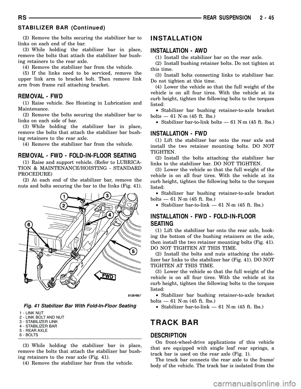
(1) Raise and support vehicle. (Refer to LUBRICA-
TION & MAINTENANCE/HOISTING - STANDARD
PROCEDURE)
(2) At each end of the stabilizer bar, remove the
nuts and bolts securing the bar to the links (Fig. 41).
(3) While holding the stabilizer bar in place,
remove the bolts that attach the stabilizer bar bush-
ing retainers to the rear axle (Fig. 41).
(4) Remove the stabilizer bar from the vehicle.
INSTALLATION
INSTALLATION - AWD
(1) Install the stabilizer bar on the rear axle.
(2) Install bushing retainer bolts. Do not tighten at
this time.
(3) Install bolts connecting links to stabilizer bar.
Do not tighten at this time.
(4) Lower the vehicle so that the full weight of the
vehicle is on all four tires. With the vehicle at its
curb height, tighten the following bolts to the torques
listed:
²Stabilizer bar bushing retainer-to-axle bracket
bolts Ð 61 N´m (45 ft. lbs.)
²Stabilizer bar-to-link bolts Ð 61 N´m (45 ft. lbs.)
INSTALLATION - FWD
(1) Lift the stabilizer bar onto the rear axle and
install the two retainer mounting bolts. DO NOT
TIGHTEN.
(2) Install the bolts attaching the stabilizer bar
links to the stabilizer bar. DO NOT TIGHTEN.
(3) Lower the vehicle so that the full weight of the
vehicle is on all four tires. With the vehicle at its
curb height, tighten the following bolts to the torques
listed:
²Stabilizer bar bushing retainer-to-axle bracket
bolts Ð 61 N´m (45 ft. lbs.)
²Stabilizer bar-to-link Ð 61 N´m (45 ft. lbs.)
INSTALLATION - FWD - FOLD-IN-FLOOR
SEATING
(1) Lift the stabilizer bar onto the rear axle, hook-
ing the bottom of the bushing retainers on the axle,
then install the two retainer mounting bolts (Fig. 41).
DO NOT TIGHTEN AT THIS TIME.
(2) Install the bolts and nuts attaching the stabi-
lizer bar links to the stabilizer bar (Fig. 41). DO NOT
TIGHTEN AT THIS TIME.
(3) Lower the vehicle so that the full weight of the
vehicle is on all four tires. With the vehicle at its
curb height, tighten the following bolts to the torques
listed:
²Stabilizer bar bushing retainer-to-axle bracket
bolts Ð 61 N´m (45 ft. lbs.)
²Stabilizer bar-to-link Ð 61 N´m (45 ft. lbs.)
TRACK BAR
DESCRIPTION
On front-wheel-drive applications of this vehicle
that are equipped with single leaf rear springs, a
track bar is used on the rear axle (Fig. 1).
The track bar connects the rear axle to the frame/
body of the vehicle. The track bar is isolated from the
Fig. 41 Stabilizer Bar With Fold-In-Floor Seating
1 - LINK NUT
2 - LINK BOLT AND NUT
3 - STABILIZER LINK
4 - STABILIZER BAR
5 - REAR AXLE
6 - BOLTS
RSREAR SUSPENSION2-45
STABILIZER BAR (Continued)
Page 94 of 2339

NOTE: Prior to reading the vehicle's alignment
readouts, the front and rear of vehicle should be
jounced. Induce jounce (rear first, then front) by
grasping the center of the bumper and jouncing
each end of vehicle an equal number of times. The
bumper should always be released when vehicle is
at the bottom of the jounce cycle.
(3) Read the vehicle's current front and rear align-
ment settings. Compare the vehicle's current align-
ment settings to the vehicle specifications for camber,
caster and toe-in. (Refer to 2 - SUSPENSION/
WHEEL ALIGNMENT - SPECIFICATIONS)
(4) If front camber and caster are not within spec-
ifications, proceed to CAMBER AND CASTER below.
If caster and camber are within specifications, pro-
ceed to TOE which can be found following CAMBER
AND CASTER. Rear camber, caster and toe are not
adjustable. If found not to be within specifications,
reinspect for damaged suspension or body compo-
nents and replace as necessary.
CAMBER AND CASTER
Camber and caster settings on this vehicle are
determined at the time the vehicle is designed, by
the location of the vehicle's suspension components.
This is referred to as NET BUILD. The result is no
required adjustment of camber and caster after the
vehicle is built or when servicing the suspension
components. Thus, when performing a wheel align-
ment, caster and camber are not normally considered
adjustable angles. Camber and caster should be
checked to ensure they meet vehicle specifications.
If front camber is found not to meet alignment
specifications, it can be adjusted using an available
camber adjustment bolt package. Before installing a
camber adjustment bolt package on a vehicle found
to be outside the specifications, inspect the suspen-
sion components for any signs of damage or bending.
CAUTION: Do not attempt to adjust the vehicles
wheel alignment by heating, bending or by perform-
ing any other modification to the vehicle's front
suspension components or body.
If camber readings are not within specifications,
use the following procedure to install the front cam-
ber adjustment bolt package and then adjust front
camber.
CAMBER ADJUSTMENT BOLT PACKAGE INSTALLATION
The camber adjustment bolt package contains 2
flange bolts, 2 cam bolts, 2 dog bone washers, and 4
nuts. This package services both sides of the vehicle.
Use the package to attach the strut clevis bracket to
the steering knuckle after the strut clevis brackethas been modified. To install and adjust the camber
adjustment bolt package, follow the procedure below.
(1) Raise the vehicle until its tires are not support-
ing the weight of the vehicle.
(2) Remove the front tire and wheel assemblies.
CAUTION: When removing the steering knuckle
from the strut clevis bracket, do not put a strain on
the brake flex hose. Also, do not let the weight of
the steering knuckle assembly be supported by the
brake flex hose when removed from the strut
assembly. If necessary use a wire hanger to sup-
port the steering knuckle assembly or if required
remove the brake flex hose from the caliper assem-
bly.
CAUTION: The knuckle to strut assembly attaching
bolt shanks are serrated and must not be turned
during removal. Remove the nuts while holding the
bolts stationary.
(3) Remove the top and bottom, strut clevis
bracket to steering knuckle attaching bolts (Fig.
7)and discard. Separate the steering knuckle from
the strut clevis bracket and position steering knuckle
so it is out of the way of the strut.
CAUTION: When slotting the bottom mounting hole
on the strut clevis bracket, do not enlarge the hole
beyond the indentations on the sides of the strut
clevis bracket (Fig. 8).
Fig. 7 Clevis Bracket To Steering Knuckle Attaching
Bolts
1 - STRUT CLEVIS BRACKET
2 - ATTACHING BOLTS
3 - TIE ROD END
4 - ROTOR
5 - STEERING KNUCKLE
RSWHEEL ALIGNMENT2-53
WHEEL ALIGNMENT (Continued)
Page 95 of 2339
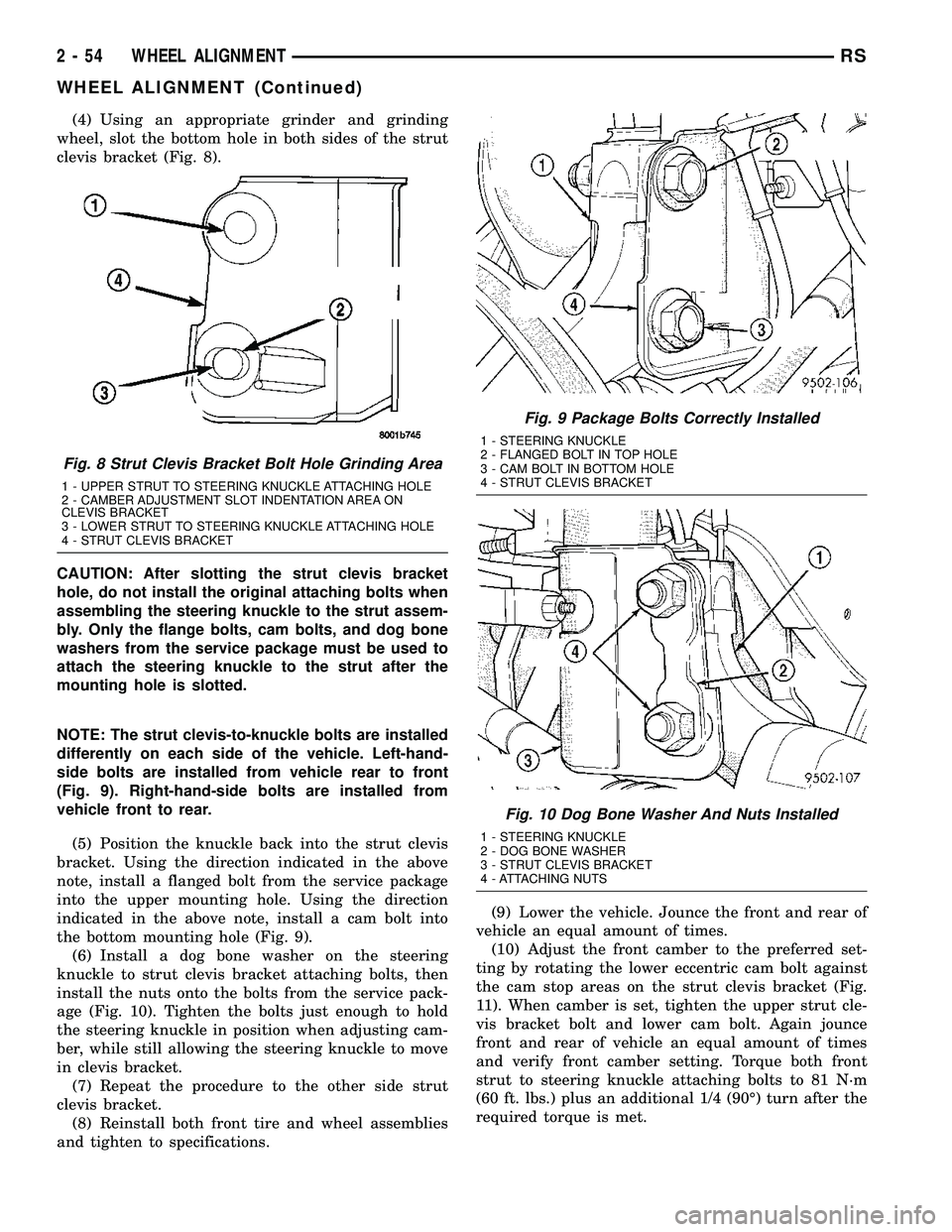
(4) Using an appropriate grinder and grinding
wheel, slot the bottom hole in both sides of the strut
clevis bracket (Fig. 8).
CAUTION: After slotting the strut clevis bracket
hole, do not install the original attaching bolts when
assembling the steering knuckle to the strut assem-
bly. Only the flange bolts, cam bolts, and dog bone
washers from the service package must be used to
attach the steering knuckle to the strut after the
mounting hole is slotted.
NOTE: The strut clevis-to-knuckle bolts are installed
differently on each side of the vehicle. Left-hand-
side bolts are installed from vehicle rear to front
(Fig. 9). Right-hand-side bolts are installed from
vehicle front to rear.
(5) Position the knuckle back into the strut clevis
bracket. Using the direction indicated in the above
note, install a flanged bolt from the service package
into the upper mounting hole. Using the direction
indicated in the above note, install a cam bolt into
the bottom mounting hole (Fig. 9).
(6) Install a dog bone washer on the steering
knuckle to strut clevis bracket attaching bolts, then
install the nuts onto the bolts from the service pack-
age (Fig. 10). Tighten the bolts just enough to hold
the steering knuckle in position when adjusting cam-
ber, while still allowing the steering knuckle to move
in clevis bracket.
(7) Repeat the procedure to the other side strut
clevis bracket.
(8) Reinstall both front tire and wheel assemblies
and tighten to specifications.(9) Lower the vehicle. Jounce the front and rear of
vehicle an equal amount of times.
(10) Adjust the front camber to the preferred set-
ting by rotating the lower eccentric cam bolt against
the cam stop areas on the strut clevis bracket (Fig.
11). When camber is set, tighten the upper strut cle-
vis bracket bolt and lower cam bolt. Again jounce
front and rear of vehicle an equal amount of times
and verify front camber setting. Torque both front
strut to steering knuckle attaching bolts to 81 N´m
(60 ft. lbs.) plus an additional 1/4 (90É) turn after the
required torque is met.
Fig. 8 Strut Clevis Bracket Bolt Hole Grinding Area
1 - UPPER STRUT TO STEERING KNUCKLE ATTACHING HOLE
2 - CAMBER ADJUSTMENT SLOT INDENTATION AREA ON
CLEVIS BRACKET
3 - LOWER STRUT TO STEERING KNUCKLE ATTACHING HOLE
4 - STRUT CLEVIS BRACKET
Fig. 9 Package Bolts Correctly Installed
1 - STEERING KNUCKLE
2 - FLANGED BOLT IN TOP HOLE
3 - CAM BOLT IN BOTTOM HOLE
4 - STRUT CLEVIS BRACKET
Fig. 10 Dog Bone Washer And Nuts Installed
1 - STEERING KNUCKLE
2 - DOG BONE WASHER
3 - STRUT CLEVIS BRACKET
4 - ATTACHING NUTS
2 - 54 WHEEL ALIGNMENTRS
WHEEL ALIGNMENT (Continued)
Page 102 of 2339
(6) Slide half shaft back into front hub and bear-
ing assembly.
CAUTION: The steering knuckle to strut assembly
attaching bolts are serrated and must not be turned
during installation. Install nuts while holding bolts
stationary in the steering knuckle.
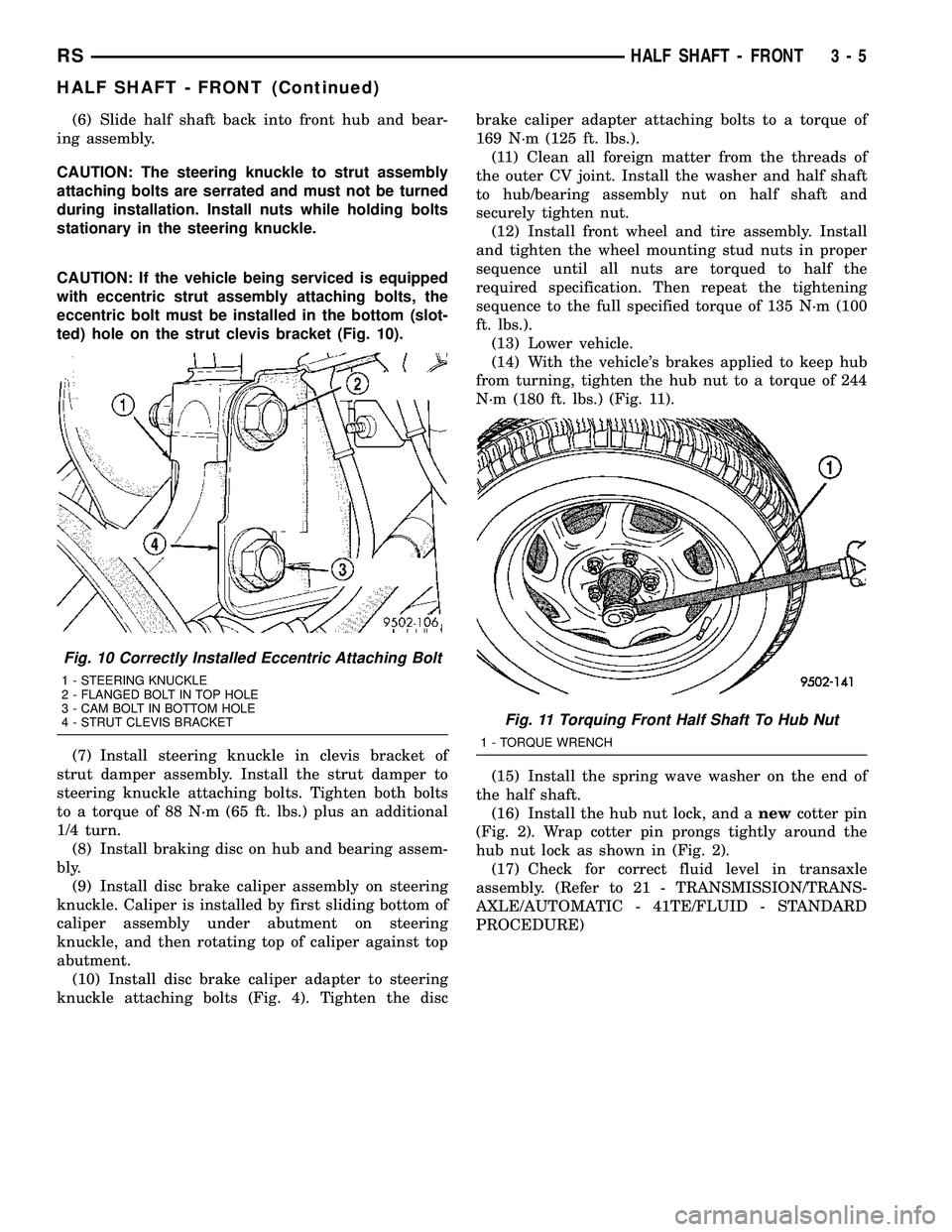
CAUTION: If the vehicle being serviced is equipped
with eccentric strut assembly attaching bolts, the
eccentric bolt must be installed in the bottom (slot-
ted) hole on the strut clevis bracket (Fig. 10).
(7) Install steering knuckle in clevis bracket of
strut damper assembly. Install the strut damper to
steering knuckle attaching bolts. Tighten both bolts
to a torque of 88 N´m (65 ft. lbs.) plus an additional
1/4 turn.
(8) Install braking disc on hub and bearing assem-
bly.
(9) Install disc brake caliper assembly on steering
knuckle. Caliper is installed by first sliding bottom of
caliper assembly under abutment on steering
knuckle, and then rotating top of caliper against top
abutment.
(10) Install disc brake caliper adapter to steering
knuckle attaching bolts (Fig. 4). Tighten the discbrake caliper adapter attaching bolts to a torque of
169 N´m (125 ft. lbs.).
(11) Clean all foreign matter from the threads of
the outer CV joint. Install the washer and half shaft
to hub/bearing assembly nut on half shaft and
securely tighten nut.
(12) Install front wheel and tire assembly. Install
and tighten the wheel mounting stud nuts in proper
sequence until all nuts are torqued to half the
required specification. Then repeat the tightening
sequence to the full specified torque of 135 N´m (100
ft. lbs.).
(13) Lower vehicle.
(14) With the vehicle's brakes applied to keep hub
from turning, tighten the hub nut to a torque of 244
N´m (180 ft. lbs.) (Fig. 11).
(15) Install the spring wave washer on the end of
the half shaft.
(16) Install the hub nut lock, and anewcotter pin
(Fig. 2). Wrap cotter pin prongs tightly around the
hub nut lock as shown in (Fig. 2).
(17) Check for correct fluid level in transaxle
assembly. (Refer to 21 - TRANSMISSION/TRANS-
AXLE/AUTOMATIC - 41TE/FLUID - STANDARD
PROCEDURE)
Fig. 10 Correctly Installed Eccentric Attaching Bolt
1 - STEERING KNUCKLE
2 - FLANGED BOLT IN TOP HOLE
3 - CAM BOLT IN BOTTOM HOLE
4 - STRUT CLEVIS BRACKET
Fig. 11 Torquing Front Half Shaft To Hub Nut
1 - TORQUE WRENCH
RSHALF SHAFT - FRONT3-5
HALF SHAFT - FRONT (Continued)
Page 103 of 2339
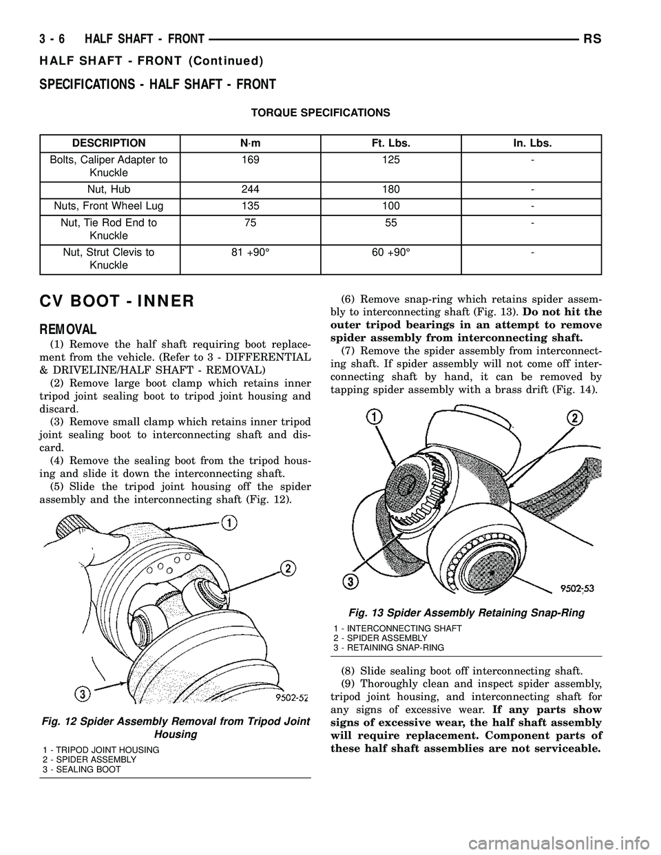
SPECIFICATIONS - HALF SHAFT - FRONT
TORQUE SPECIFICATIONS
DESCRIPTION N´m Ft. Lbs. In. Lbs.
Bolts, Caliper Adapter to
Knuckle169 125 -
Nut, Hub 244 180 -
Nuts, Front Wheel Lug 135 100 -
Nut, Tie Rod End to
Knuckle75 55 -
Nut, Strut Clevis to
Knuckle81 +90É 60 +90É -
CV BOOT - INNER
REMOVAL
(1) Remove the half shaft requiring boot replace-
ment from the vehicle. (Refer to 3 - DIFFERENTIAL
& DRIVELINE/HALF SHAFT - REMOVAL)
(2) Remove large boot clamp which retains inner
tripod joint sealing boot to tripod joint housing and
discard.
(3) Remove small clamp which retains inner tripod
joint sealing boot to interconnecting shaft and dis-
card.
(4) Remove the sealing boot from the tripod hous-
ing and slide it down the interconnecting shaft.
(5) Slide the tripod joint housing off the spider
assembly and the interconnecting shaft (Fig. 12).(6) Remove snap-ring which retains spider assem-
bly to interconnecting shaft (Fig. 13).Do not hit the
outer tripod bearings in an attempt to remove
spider assembly from interconnecting shaft.
(7) Remove the spider assembly from interconnect-
ing shaft. If spider assembly will not come off inter-
connecting shaft by hand, it can be removed by
tapping spider assembly with a brass drift (Fig. 14).
(8) Slide sealing boot off interconnecting shaft.
(9) Thoroughly clean and inspect spider assembly,
tripod joint housing, and interconnecting shaft for
any signs of excessive wear.If any parts show
signs of excessive wear, the half shaft assembly
will require replacement. Component parts of
these half shaft assemblies are not serviceable.
Fig. 12 Spider Assembly Removal from Tripod Joint
Housing
1 - TRIPOD JOINT HOUSING
2 - SPIDER ASSEMBLY
3 - SEALING BOOT
Fig. 13 Spider Assembly Retaining Snap-Ring
1 - INTERCONNECTING SHAFT
2 - SPIDER ASSEMBLY
3 - RETAINING SNAP-RING
3 - 6 HALF SHAFT - FRONTRS
HALF SHAFT - FRONT (Continued)
Page 105 of 2339

(3) Install the spider assembly to interconnecting
shaft retaining snap-ring into groove on end of inter-
connecting shaft (Fig. 18). Be sure the snap-ring is
fully seated into groove on interconnecting shaft.
(4) Distribute 1/2 the amount of grease provided in
the seal boot service package (DO NOT USE ANY
OTHER TYPE OF GREASE) into tripod housing. Put
the remaining amount into the sealing boot.
(5) Align tripod housing with spider assembly and
then slide tripod housing over spider assembly and
interconnecting shaft (Fig. 19).
(6) Install inner CV joint seal boot to interconnect-
ing shaft clamp evenly on sealing boot.(7) Place crimping tool C-4975-A over bridge of
clamp (Fig. 20).
(8) Tighten nut on crimping tool C-4975-A until
jaws on tool are closed completely together, face to
face (Fig. 21).
CAUTION: Seal boot must not be dimpled, stretched
or out of shape in any way. If seal boot is NOT
shaped correctly, equalize pressure in seal and
shape it by hand.
Fig. 18 Spider Assembly Retaining Snap-Ring
Installed
1 - INTERCONNECTING SHAFT
2 - SPIDER ASSEMBLY
3 - RETAINING SNAP-RING
Fig. 19 Installing Tripod Housing on Spider
Assembly
1 - TRIPOD JOINT HOUSING
2 - SPIDER ASSEMBLY
3 - SEALING BOOT
Fig. 20 Crimping Tool Installed on Sealing Boot
Clamp - Typical
1 - SPECIAL TOOL C-4975-A
2 - INTERCONNECTING SHAFT
3 - CLAMP
4 - SEALING BOOT
Fig. 21 Sealing Boot Retaining Clamp Installed -
Typical
1 - CLAMP
2 - JAWS OF SPECIAL TOOL C-4975-A MUST BE CLOSED
COMPLETELY TOGETHER HERE
3 - INTERCONNECTING SHAFT
4 - SEALING BOOT
3 - 8 HALF SHAFT - FRONTRS
CV BOOT - INNER (Continued)