brake light CHRYSLER VOYAGER 2005 Workshop Manual
[x] Cancel search | Manufacturer: CHRYSLER, Model Year: 2005, Model line: VOYAGER, Model: CHRYSLER VOYAGER 2005Pages: 2339, PDF Size: 59.69 MB
Page 520 of 2339
(28) Install two right side nuts at instrument
panel center stack support to floor.
(29) Install two left side nuts at instrument panel
center stack support to floor.
(30) Connect the two wiring connectors to lower
instrument panel cubby bin at bottom of center stack
and install six screws.
(31) Align left side upper A-pillar trim over retain-
ing slots and firmly snap into place.
(32) Install four nuts at brake pedal support
bracket to instrument panel.
(33) Align left A-pillar lower extension trim over
retaining slots and firmly snap into place.
(34) Install knee blocker and retaining screws.
(35) Install Data Link Connector (DLC) into bot-
tom of knee blocker.
(36) Align parking brake lever and snap into place
on knee blocker reinforcement.
(37) Install lower steering column cover and four
retaining screws
(38) Align left cowl panel over retaining slots and
firmly snap into place.
(39) Align left front door sill plate over retaining
slots and firmly snap into place.
(40) Install center console bin between front seats.
WARNING: Do not connect the battery negative
cable (Refer to 8 - ELECTRICAL/RESTRAINTS -
DIAGNOSIS AND TESTING - AIRBAG SYSTEM). Per-
sonal injury or death may result if the system test
is not performed first.
(41) Close hood.
(42) Verify system and vehicle operation.
PASSENGER AIRBAG
DISABLED INDICATOR
DESCRIPTION
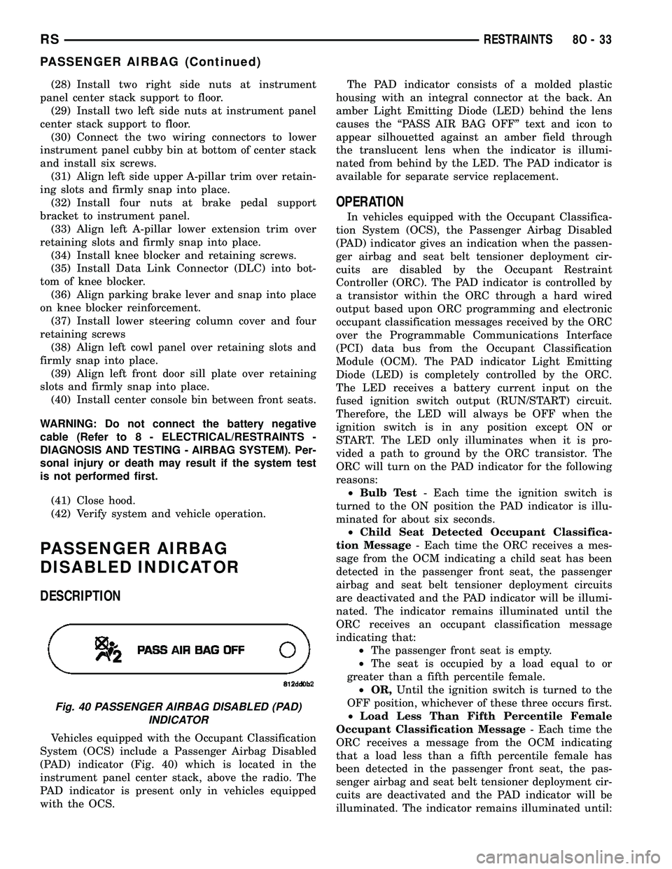
Vehicles equipped with the Occupant Classification
System (OCS) include a Passenger Airbag Disabled
(PAD) indicator (Fig. 40) which is located in the
instrument panel center stack, above the radio. The
PAD indicator is present only in vehicles equipped
with the OCS.The PAD indicator consists of a molded plastic
housing with an integral connector at the back. An
amber Light Emitting Diode (LED) behind the lens
causes the ªPASS AIR BAG OFFº text and icon to
appear silhouetted against an amber field through
the translucent lens when the indicator is illumi-
nated from behind by the LED. The PAD indicator is
available for separate service replacement.
OPERATION
In vehicles equipped with the Occupant Classifica-
tion System (OCS), the Passenger Airbag Disabled
(PAD) indicator gives an indication when the passen-
ger airbag and seat belt tensioner deployment cir-
cuits are disabled by the Occupant Restraint
Controller (ORC). The PAD indicator is controlled by
a transistor within the ORC through a hard wired
output based upon ORC programming and electronic
occupant classification messages received by the ORC
over the Programmable Communications Interface
(PCI) data bus from the Occupant Classification
Module (OCM). The PAD indicator Light Emitting
Diode (LED) is completely controlled by the ORC.
The LED receives a battery current input on the
fused ignition switch output (RUN/START) circuit.
Therefore, the LED will always be OFF when the
ignition switch is in any position except ON or
START. The LED only illuminates when it is pro-
vided a path to ground by the ORC transistor. The
ORC will turn on the PAD indicator for the following
reasons:
²Bulb Test- Each time the ignition switch is
turned to the ON position the PAD indicator is illu-
minated for about six seconds.
²Child Seat Detected Occupant Classifica-
tion Message- Each time the ORC receives a mes-
sage from the OCM indicating a child seat has been
detected in the passenger front seat, the passenger
airbag and seat belt tensioner deployment circuits
are deactivated and the PAD indicator will be illumi-
nated. The indicator remains illuminated until the
ORC receives an occupant classification message
indicating that:
²The passenger front seat is empty.
²The seat is occupied by a load equal to or
greater than a fifth percentile female.
²OR,Until the ignition switch is turned to the
OFF position, whichever of these three occurs first.
²Load Less Than Fifth Percentile Female
Occupant Classification Message- Each time the
ORC receives a message from the OCM indicating
that a load less than a fifth percentile female has
been detected in the passenger front seat, the pas-
senger airbag and seat belt tensioner deployment cir-
cuits are deactivated and the PAD indicator will be
illuminated. The indicator remains illuminated until:
Fig. 40 PASSENGER AIRBAG DISABLED (PAD)
INDICATOR
RSRESTRAINTS8O-33
PASSENGER AIRBAG (Continued)
Page 534 of 2339
OPERATION
The PCM on NGC vehicles first senses that the
speed control is set. If the set speed is exceeded by
more than 4 mph (6.5 km/hr) and the throttle is
closed, the PCM on NGC vehicles causes the trans-
axle to downshift to THIRD gear. After downshifting,
the automatic speed control resumes normal opera-
tion. To ensure that an upshift is appropriate after
the set speed is reached, the PCM on NGC vehicles
waits until the speed control system opens the throt-
tle at least 6 degrees before upshifting to OVER-
DRIVE again.
If the driver applies the brakes, canceling auto-
matic speed control operation with the transaxle still
in THIRD gear, the PCM on NGC vehicles maintains
this gear until the driver opens the throttle at least 6
degrees to avoid an inappropriate upshift. The
upshift is also delayed for 2.5 seconds after reaching
the 6 degrees throttle opening in anticipation that
the driver might open the throttle enough to require
THIRD gear. This will avoid unnecessary and dis-
turbing transmission cycling. If the automatic speed
control RESUME feature is used after braking, the
upshift is delayed until the set speed is achieved to
reduce cycling and provide better response.
DIAGNOSIS AND TESTING - ROAD TEST
Perform a vehicle road test to verify reports of
speed control system malfunction. The road test
should include attention to the speedometer. Speed-
ometer operation should be smooth and without flut-
ter at all speeds.Flutter in the speedometer indicates a problem
which might cause surging in the speed control sys-
tem. The cause of any speedometer problems should
be corrected before proceeding. Refer to the Instru-
ment Cluster for speedometer diagnosis.
If a road test verifies an inoperative system, and
the speedometer operates properly, check for:
²A Diagnostic Trouble Code (DTC). If a DTC
exists, conduct tests per the Powertrain Diagnostic
Procedures manual.
²A misadjusted brake (stop) lamp switch. This
could also cause an intermittent problem.
²Loose or corroded electrical connections at the
servo. Corrosion should be removed from electrical
terminals and a light coating of Mopar Multipurpose
Grease, or equivalent, applied.
²Leaking vacuum reservoir.
²Loose or leaking vacuum hoses or connections.
²Defective one-way vacuum check valve.
²Secure attachment at both ends of the speed
control servo cable.
²Smooth operation of throttle linkage and throttle
body air valve.
²Conduct electrical test at PCM.
²Failed speed control servo. Do the servo vacuum
test.
CAUTION: When test probing for voltage or conti-
nuity at electrical connectors, care must be taken
not to damage connector, terminals or seals. If
these components are damaged, intermittent or
complete system failure may occur.
SPECIFICATIONS - TORQUE
DESCRIPTION N´m Ft. Lbs. In. Lbs.
Servo Mounting Bracket
Nuts14 10.3 123.9
Servo Mounting Bracket
Bolts14 10.3 123.9
Servo Mounting Nuts 6.7 60
RSSPEED CONTROL8P-3
SPEED CONTROL (Continued)
Page 564 of 2339
WIRING
TABLE OF CONTENTS
page page
WIRING DIAGRAM INFORMATION....... 8W-01-1
COMPONENT INDEX.................. 8W-02-1
POWER DISTRIBUTION............... 8W-10-1
GROUND DISTRIBUTION.............. 8W-15-1
BUS COMMUNICATIONS.............. 8W-18-1
CHARGING SYSTEM.................. 8W-20-1
STARTING SYSTEM.................. 8W-21-1
FUEL/IGNITION SYSTEM.............. 8W-30-1
TRANSMISSION CONTROL SYSTEM..... 8W-31-1
VEHICLE SPEED CONTROL............ 8W-33-1
ANTILOCK BRAKES................... 8W-35-1
VEHICLE THEFT SECURITY SYSTEM..... 8W-39-1
INSTRUMENT CLUSTER............... 8W-40-1
HORN/CIGAR LIGHTER/POWER OUTLET . . 8W-41-1
AIR CONDITIONING-HEATER........... 8W-42-1
OCCUPANT RESTRAINT SYSTEM........ 8W-43-1
INTERIOR LIGHTING.................. 8W-44-1
BODY CONTROL MODULE............. 8W-45-1
MESSAGE CENTER................... 8W-46-1
AUDIO SYSTEM..................... 8W-47-1REAR WINDOW DEFOGGER............ 8W-48-1
OVERHEAD CONSOLE................. 8W-49-1
FRONT LIGHTING.................... 8W-50-1
REAR LIGHTING..................... 8W-51-1
TURN SIGNALS...................... 8W-52-1
WIPERS............................ 8W-53-1
TRAILER TOW....................... 8W-54-1
NAVIGATION/TELECOMMUNICATIONS.... 8W-55-1
CONVENIENCE SYSTEMS.............. 8W-56-1
POWER WINDOWS................... 8W-60-1
POWER DOOR LOCKS................ 8W-61-1
POWER MIRRORS................... 8W-62-1
POWER SEATS...................... 8W-63-1
POWER SUNROOF................... 8W-64-1
SPLICE INFORMATION................ 8W-70-1
CONNECTOR PIN-OUTS............... 8W-80-1
CONNECTOR/GROUND/SPLICE
LOCATION........................ 8W-91-1
POWER DISTRIBUTION SYSTEM........ 8W-97-1 RSWIRING
8W-1
Page 571 of 2339
DESCRIPTION - CIRCUIT FUNCTIONS
All circuits in the diagrams use an alpha/numeric
code to identify the wire and it's function. To identify
which circuit code applies to a system, refer to the
Circuit Identification Code Chart. This chart shows
the main circuits only and does not show the second-
ary codes that may apply to some models.
CIRCUIT IDENTIFICATION CODE CHART
CIRCUIT FUNCTION
A BATTERY FEED
B BRAKE CONTROLS
C CLIMATE CONTROLS
D DIAGNOSTIC CIRCUITS
E DIMMING ILLUMINATION
CIRCUITS
F FUSED CIRCUITS
G MONITORING CIRCUITS
(GAUGES)
H MULTIPLE
I NOT USED
J OPEN
K POWERTRAIN CONTROL
MODULE
L EXTERIOR LIGHTING
M INTERIOR LIGHTING
N MULTIPLE
O NOT USED
P POWER OPTION (BATTERY
FEED)
Q POWER OPTIONS (IGNITION
FEED)
R PASSIVE RESTRAINT
S SUSPENSION/STEERING
T TRANSMISSION/TRANSAXLE/
TRANSFER CASE
U OPEN
V SPEED CONTROL, WIPER/
WASHER
W WIPERS
X AUDIO SYSTEMS
Y TEMPORARY
Z GROUNDS
DESCRIPTION - SECTION IDENTIFICATION AND
INFORMATION
The wiring diagrams are grouped into individual
sections. If a component is most likely found in a par-
ticular group, it will be shown complete (all wires,
connectors, and pins) within that group. For exam-
ple, the Auto Shutdown Relay is most likely to be
found in Group 30, so it is shown there complete. It
can, however, be shown partially in another group if
it contains some associated wiring.
Splice diagrams in Section 8W-70 show the entire
splice and provide references to other sections the
splices serves. Section 8W-70 only contains splice dia-
grams that are not shown in their entirety some-
where else in the wiring diagrams.
Section 8W-80 shows each connector and the cir-
cuits involved with that connector. The connectors
are identified using the name/number on the dia-
gram pages.
WIRING SECTION CHART
GROUP TOPIC
8W-01 thru
8W-09General information and Diagram
Overview
8W-10 thru
8W-19Main Sources of Power and
Vehicle Grounding
8W-20 thru
8W-29Starting and Charging
8W-30 thru
8W-39Powertrain/Drivetrain Systems
8W-40 thru
8W-49Body Electrical items and A/C
8W-50 thru
8W-59Exterior Lighting, Wipers and
Trailer Tow
8W-60 thru
8W-69Power Accessories
8W-70 Splice Information
8W-80 Connector Pin Outs
8W-91 Connector, Ground and Splice
Locations
8W - 01 - 6 8W-01 WIRING DIAGRAM INFORMATIONRS
WIRING DIAGRAM INFORMATION (Continued)
Page 582 of 2339
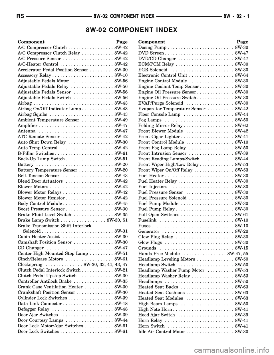
8W-02 COMPONENT INDEX
Component Page
A/C Compressor Clutch................. 8W-42
A/C Compressor Clutch Relay............ 8W-42
A/C Pressure Sensor................... 8W-42
A/C-Heater Control.................... 8W-42
Accelerator Pedal Position Sensor......... 8W-30
Accessory Relay....................... 8W-10
Adjustable Pedals Motor................ 8W-56
Adjustable Pedals Relay................ 8W-56
Adjustable Pedals Sensor............... 8W-56
Adjustable Pedals Switch............... 8W-56
Airbag.............................. 8W-43
Airbag On/Off Indicator Lamp............ 8W-43
Airbag Squibs........................ 8W-43
Ambient Temperature Sensor............ 8W-49
Amplifier............................ 8W-47
Antenna............................ 8W-47
ATC Remote Sensor.................... 8W-42
Auto Shut Down Relay................. 8W-30
Auto Temp Control.................... 8W-42
B-Pillar Switches...................... 8W-61
Back-Up Lamp Switch.................. 8W-51
Battery............................. 8W-20
Battery Temperature Sensor............. 8W-20
Belt Tension Sensor.................... 8W-43
Blend Door Actuators.................. 8W-42
Blower Motors........................ 8W-42
Blower Motor Relays................... 8W-42
Blower Motor Resistor.................. 8W-42
Body Control Module................... 8W-45
Boost Pressure Sensor.................. 8W-30
Brake Fluid Level Switch............... 8W-35
Brake Lamp Switch................. 8W-30, 51
Brake Transmission Shift Interlock
Solenoid........................... 8W-31
Cabin Heater Assist................... 8W-30
Camshaft Position Sensor............... 8W-30
CD Changer......................... 8W-47
Center High Mounted Stop Lamp......... 8W-51
Cinch/Release Motors.................. 8W-61
Clockspring.............. 8W-30, 33, 41, 43, 47
Clutch Pedal Interlock Switch............ 8W-21
Clutch Pedal Upstop Switch............. 8W-30
Controller Antilock Brake............... 8W-35
Crank Case Ventilation Heater........... 8W-30
Crankshaft Position Sensor.............. 8W-30
Cylinder Lock Switches................. 8W-39
Data Link Connector................... 8W-18
Defogger Relay....................... 8W-48
Door Ajar Switches.................... 8W-39
Door Courtesy Lamps.................. 8W-44
Door Lock Motor/Ajar Switches........... 8W-61
Door Lock Switches.................... 8W-61Component Page
Dosing Pump......................... 8W-30
DVD Screen.......................... 8W-47
DVD/CD Changer..................... 8W-47
ECM/PCM Relay...................... 8W-30
EGR Solenoid........................ 8W-30
Electronic Control Unit................. 8W-64
Engine Control Module................. 8W-30
Engine Coolant Temp Sensor............. 8W-30
Engine Oil Pressure Sensor.............. 8W-30
Engine Oil Pressure Switch.............. 8W-30
EVAP/Purge Solenoid.................. 8W-30
Evaporator Temperature Sensor.......... 8W-42
Floor Console Lamp................... 8W-44
Fog Lamps.......................... 8W-50
Folding Mirror Relay................... 8W-62
Front Blower Module.................. 8W-42
Front Cigar Lighter.................... 8W-41
Front Control Module.................. 8W-10
Front Fog Lamp Relay................. 8W-50
Front Intrusion Sensor................. 8W-39
Front Reading Lamps/Switch............ 8W-44
Front Wiper High/Low Relay............. 8W-53
Front Wiper On/Off Relay............... 8W-53
Fuel Heater.......................... 8W-30
Fuel Heater Relay..................... 8W-30
Fuel Injectors........................ 8W-30
Fuel Pressure Sensor.................. 8W-30
Fuel Pressure Solenoid................. 8W-30
Fuel Pump Module.................... 8W-30
Fuel Pump Relay...................... 8W-30
Full Open Switches.................... 8W-61
Fuselink............................ 8W-10
Fuses............................... 8W-10
Generator........................... 8W-20
Glow Plug Relay...................... 8W-30
Glow Plugs.......................... 8W-30
Grounds............................ 8W-15
Hands Free Module................. 8W-47, 55
Headlamp Leveling Motors.............. 8W-50
Headlamp Switch..................... 8W-50
Headlamp Washer Pump Motor.......... 8W-53
Headlamp Washer Relay................ 8W-53
Headlamps.......................... 8W-50
Heated Seat Backs.................... 8W-63
Heated Seat Cushions.................. 8W-63
Heated Seat Modules.................. 8W-63
High Beam Lamps..................... 8W-50
High Note Horn....................... 8W-41
Hood Ajar Switch..................... 8W-39
Horn Relay.......................... 8W-41
Horn Switch......................... 8W-41
Idle Air Control Motor.................. 8W-30
RS8W-02 COMPONENT INDEX8W-02-1
Page 584 of 2339

8W-10 POWER DISTRIBUTION
Component Page
A/C Compressor Clutch...... 8W-10-22, 24, 45, 48
A/C Compressor
Clutch Relay......... 8W-10-22, 24, 44, 45, 48
Accessory Relay............... 8W-10-16, 31, 65
Adjustable Pedals Relay........... 8W-10-47, 60
Adjustable Pedals Switch.......... 8W-10-40, 47
Ambient Temperature Sensor.......... 8W-10-62
Amplifier....................... 8W-10-32, 50
Auto Shut Down Relay............ 8W-10-21, 41
Auto Temp Control.................. 8W-10-40
Back-Up Lamp Switch............... 8W-10-66
Battery............... 8W-10-13, 14, 15, 41, 48
Blower Motor Resistor............ 8W-10-19, 38
Body Control Module....... 8W-10-25, 40, 45, 49,
50, 52, 54, 55, 56, 57, 67, 68
Brake Fluid Level Switch............. 8W-10-65
Brake Lamp Switch........... 8W-10-26, 52, 67
Brake Transmission Shift Interlock
Solenoid........................ 8W-10-63
Cabin Heater Assist........... 8W-10-23, 43, 60
Camshaft Position Sensor............. 8W-10-44
Center High Mounted Stop Lamp....... 8W-10-67
Clockspring........................ 8W-10-61
Clutch Pedal Interlock
Switch.............. 8W-10-18, 37, 54, 55, 61
Controller Antilock
Brake...... 8W-10-18, 25, 36, 37, 50, 56, 62, 67
Crank Case Ventilation Heater......... 8W-10-49
Data Link Connector........... 8W-10-35, 62, 68
Defogger Relay............ 8W-10-19, 20, 39, 64
Driver Heated Seat Module........... 8W-10-50
Driver Power Seat Switch............ 8W-10-50
Driver Power Window Switch....... 8W-10-33, 34
DVD/CD Changer................... 8W-10-40
ECM/PCM Relay................. 8W-10-23, 43
EGR Solenoid...................... 8W-10-44
Engine Control Module . . . 8W-10-18, 23, 24, 37, 43,
44, 48, 62, 67
Floor Console Lamp................. 8W-10-32
Floor Console Power Outlet........ 8W-10-32, 35
Front Blower Module............. 8W-10-19, 38
Front Blower Motor Relay.... 8W-10-18, 19, 38, 64
Front Cigar Lighter.............. 8W-10-16, 32
Front Control Module....... 8W-10-15, 16, 17, 18,
19, 20, 22, 24, 26, 27,
28, 29, 30, 31, 35, 36,
37, 38, 39, 45, 47, 48,
53, 54, 55, 58, 59, 60,
61, 62, 63, 64, 65, 66,
67, 68, 69
Front Fog Lamp Relay......... 8W-10-15, 27, 64
Front Wiper High/Low Relay.... 8W-10-16, 30, 65Component Page
Front Wiper On/Off Relay....... 8W-10-16, 30, 60
Fuel Heater....................... 8W-10-49
Fuel Heater Relay............. 8W-10-24, 48, 65
Fuel Injector No. 1.................. 8W-10-42
Fuel Injector No. 2.................. 8W-10-42
Fuel Injector No. 3.................. 8W-10-42
Fuel Injector No. 4.................. 8W-10-42
Fuel Injector No. 5.................. 8W-10-42
Fuel Injector No. 6.................. 8W-10-42
Fuel Pressure Solenoid............... 8W-10-44
Fuel Pump Module............... 8W-10-22, 45
Fuel Pump Relay............. 8W-10-22, 45, 65
Fuse 1...................... 8W-10-15, 16, 27
Fuse 2...................... 8W-10-15, 28, 29
Fuse 3...................... 8W-10-15, 28, 29
Fuse 4................... 8W-10-15, 16, 17, 30
Fuse 5......................... 8W-10-16, 31
Fuse 6......................... 8W-10-16, 31
Fuse 8......................... 8W-10-17, 35
Fuse 9................ 8W-10-17, 18, 19, 36, 37
Fuse 10........................ 8W-10-19, 38
Fuse 11........................ 8W-10-16, 31
Fuse 12........................ 8W-10-19, 38
Fuse 13........................ 8W-10-20, 39
Fuse 14............ 8W-10-20, 21, 23, 39, 47, 60
Fuse 15......... 8W-10-20, 21, 22, 23, 24, 41, 43
Fuse 16.................. 8W-10-21, 23, 41, 43
Fuse 17............ 8W-10-21, 22, 23, 24, 45, 48
Fuse 18............... 8W-10-22, 24, 25, 45, 48
Fuse 19............... 8W-10-22, 24, 25, 26, 50
Fuse 20........................ 8W-10-25, 50
Fuse 21........................ 8W-10-25, 50
Fuse 22........................ 8W-10-25, 50
Fuse 23..................... 8W-10-25, 54, 55
Fuse 24........................ 8W-10-25, 52
Fuse 26..................... 8W-10-25, 26, 52
Fuse 27........................ 8W-10-26, 52
Fuse 28........................ 8W-10-16, 31
Fuse 30........................ 8W-10-26, 53
Fuse 31........................ 8W-10-26, 53
Fuse 32........................ 8W-10-26, 53
Fuselink....................... 8W-10-13, 14
G100............................. 8W-10-56
G101....................... 8W-10-41, 48, 68
G103............................. 8W-10-68
G300.......................... 8W-10-58, 59
Generator................... 8W-10-13, 14, 44
Glow Plug Relay................. 8W-10-13, 44
Hands Free Module................. 8W-10-40
Headlamp Switch................ 8W-10-29, 63
Headlamp Washer Pump Motor..... 8W-10-26, 53
Headlamp Washer Relay........ 8W-10-26, 53, 64
RS8W-10 POWER DISTRIBUTION8W-10-1
Page 654 of 2339
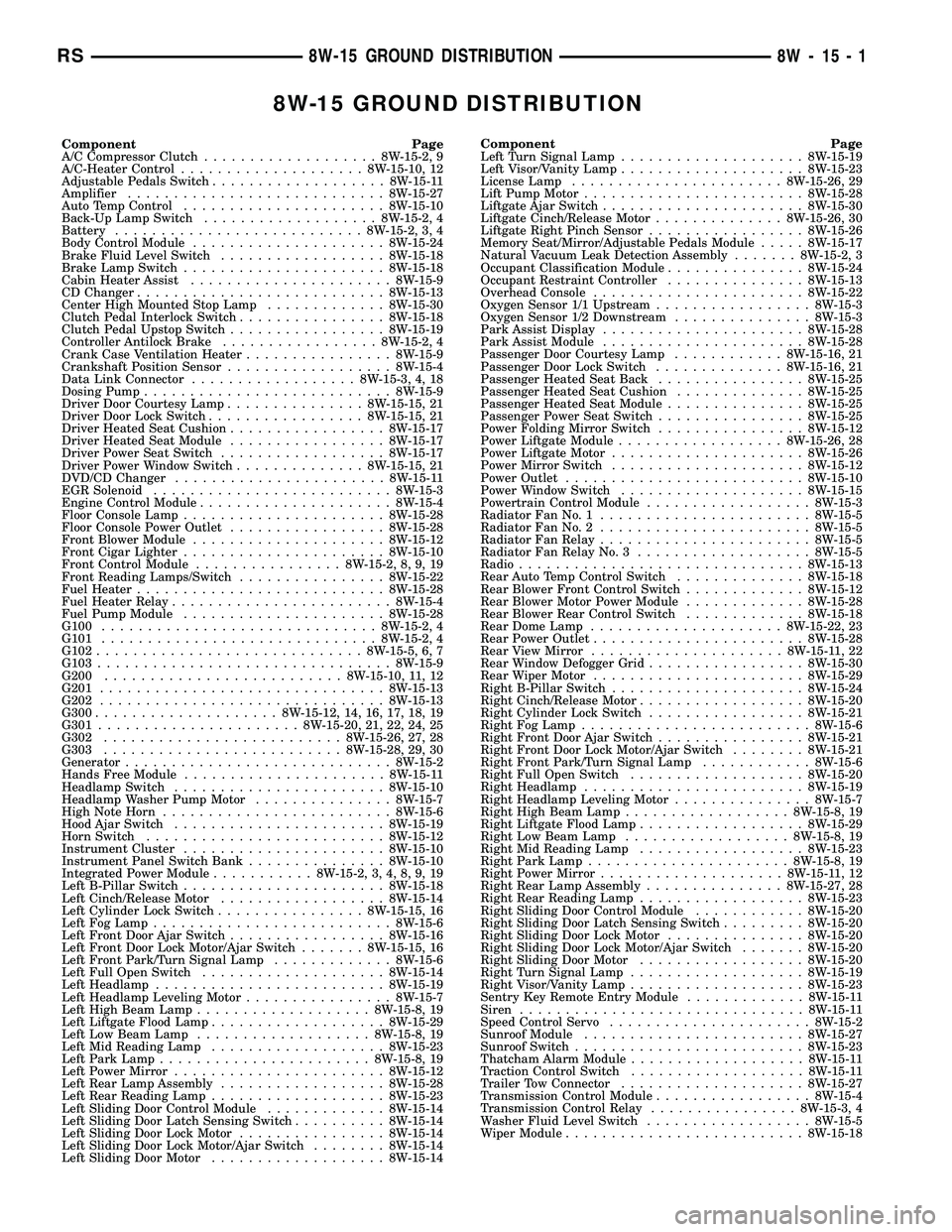
8W-15 GROUND DISTRIBUTION
Component Page
A/C Compressor Clutch...................8W-15-2, 9
A/C-Heater Control....................8W-15-10, 12
Adjustable Pedals Switch...................8W-15-11
Amplifier............................8W-15-27
Auto Temp Control......................8W-15-10
Back-Up Lamp Switch...................8W-15-2, 4
Battery...........................8W-15-2, 3, 4
Body Control Module.....................8W-15-24
Brake Fluid Level Switch..................8W-15-18
Brake Lamp Switch......................8W-15-18
Cabin Heater Assist......................8W-15-9
CD Changer...........................8W-15-13
Center High Mounted Stop Lamp.............8W-15-30
Clutch Pedal Interlock Switch................8W-15-18
Clutch Pedal Upstop Switch.................8W-15-19
Controller Antilock Brake.................8W-15-2, 4
Crank Case Ventilation Heater................8W-15-9
Crankshaft Position Sensor..................8W-15-4
Data Link Connector..................8W-15-3, 4, 18
Dosing Pump...........................8W-15-9
Driver Door Courtesy Lamp...............8W-15-15, 21
Driver Door Lock Switch.................8W-15-15, 21
Driver Heated Seat Cushion.................8W-15-17
Driver Heated Seat Module.................8W-15-17
Driver Power Seat Switch..................8W-15-17
Driver Power Window Switch..............8W-15-15, 21
DVD/CD Changer.......................8W-15-11
EGR Solenoid..........................8W-15-3
Engine Control Module.....................8W-15-4
Floor Console Lamp......................8W-15-28
Floor Console Power Outlet.................8W-15-28
Front Blower Module.....................8W-15-12
Front Cigar Lighter......................8W-15-10
Front Control Module................8W-15-2, 8, 9, 19
Front Reading Lamps/Switch................8W-15-22
Fuel Heater...........................8W-15-28
Fuel Heater Relay........................8W-15-4
Fuel Pump Module......................8W-15-28
G100..............................8W-15-2, 4
G101..............................8W-15-2, 4
G102.............................8W-15-5, 6, 7
G103................................8W-15-9
G200..........................8W-15-10, 11, 12
G201...............................8W-15-13
G202...............................8W-15-13
G300....................8W-15-12, 14, 16, 17, 18, 19
G301......................8W-15-20, 21, 22, 24, 25
G302..........................8W-15-26, 27, 28
G303..........................8W-15-28, 29, 30
Generator.............................8W-15-2
Hands Free Module......................8W-15-11
Headlamp Switch.......................8W-15-10
Headlamp Washer Pump Motor...............8W-15-7
High Note Horn.........................8W-15-6
Hood Ajar Switch.......................8W-15-19
Horn Switch..........................8W-15-12
Instrument Cluster......................8W-15-10
Instrument Panel Switch Bank...............8W-15-10
Integrated Power Module...........8W-15-2, 3, 4, 8, 9, 19
Left B-Pillar Switch......................8W-15-18
Left Cinch/Release Motor..................8W-15-14
Left Cylinder Lock Switch................8W-15-15, 16
Left Fog Lamp..........................8W-15-6
Left Front Door Ajar Switch.................8W-15-16
Left Front Door Lock Motor/Ajar Switch.......8W-15-15, 16
Left Front Park/Turn Signal Lamp.............8W-15-6
Left Full Open Switch....................8W-15-14
Left Headlamp.........................8W-15-19
Left Headlamp Leveling Motor................8W-15-7
Left High Beam Lamp...................8W-15-8, 19
Left Liftgate Flood Lamp...................8W-15-29
Left Low Beam Lamp...................8W-15-8, 19
Left Mid Reading Lamp...................8W-15-23
Left Park Lamp.......................8W-15-8, 19
Left Power Mirror.......................8W-15-12
Left Rear Lamp Assembly..................8W-15-28
Left Rear Reading Lamp...................8W-15-23
Left Sliding Door Control Module.............8W-15-14
Left Sliding Door Latch Sensing Switch..........8W-15-14
Left Sliding Door Lock Motor................8W-15-14
Left Sliding Door Lock Motor/Ajar Switch........8W-15-14
Left Sliding Door Motor...................8W-15-14Component Page
Left Turn Signal Lamp....................8W-15-19
Left Visor/Vanity Lamp....................8W-15-23
License Lamp.......................8W-15-26, 29
Lift Pump Motor........................8W-15-28
Liftgate Ajar Switch......................8W-15-30
Liftgate Cinch/Release Motor..............8W-15-26, 30
Liftgate Right Pinch Sensor.................8W-15-26
Memory Seat/Mirror/Adjustable Pedals Module.....8W-15-17
Natural Vacuum Leak Detection Assembly.......8W-15-2, 3
Occupant Classification Module...............8W-15-24
Occupant Restraint Controller...............8W-15-13
Overhead Console.......................8W-15-22
Oxygen Sensor 1/1 Upstream.................8W-15-3
Oxygen Sensor 1/2 Downstream...............8W-15-3
Park Assist Display......................8W-15-28
Park Assist Module......................8W-15-28
Passenger Door Courtesy Lamp............8W-15-16, 21
Passenger Door Lock Switch..............8W-15-16, 21
Passenger Heated Seat Back................8W-15-25
Passenger Heated Seat Cushion..............8W-15-25
Passenger Heated Seat Module...............8W-15-25
Passenger Power Seat Switch................8W-15-25
Power Folding Mirror Switch................8W-15-12
Power Liftgate Module..................8W-15-26, 28
Power Liftgate Motor.....................8W-15-26
Power Mirror Switch.....................8W-15-12
Power Outlet..........................8W-15-10
Power Window Switch....................8W-15-15
Powertrain Control Module..................8W-15-3
Radiator Fan No. 1.......................8W-15-5
Radiator Fan No. 2.......................8W-15-5
Radiator Fan Relay.......................8W-15-5
Radiator Fan Relay No. 3...................8W-15-5
Radio...............................8W-15-13
Rear Auto Temp Control Switch..............8W-15-18
Rear Blower Front Control Switch.............8W-15-12
Rear Blower Motor Power Module.............8W-15-28
Rear Blower Rear Control Switch.............8W-15-18
Rear Dome Lamp.....................8W-15-22, 23
Rear Power Outlet.......................8W-15-28
Rear View Mirror.....................8W-15-11, 22
Rear Window Defogger Grid.................8W-15-30
Rear Wiper Motor.......................8W-15-29
Right B-Pillar Switch.....................8W-15-24
Right Cinch/Release Motor..................8W-15-20
Right Cylinder Lock Switch.................8W-15-21
Right Fog Lamp.........................8W-15-6
Right Front Door Ajar Switch................8W-15-21
Right Front Door Lock Motor/Ajar Switch........8W-15-21
Right Front Park/Turn Signal Lamp............8W-15-6
Right Full Open Switch...................8W-15-20
Right Headlamp........................8W-15-19
Right Headlamp Leveling Motor...............8W-15-7
Right High Beam Lamp..................8W-15-8, 19
Right Liftgate Flood Lamp..................8W-15-29
Right Low Beam Lamp..................8W-15-8, 19
Right Mid Reading Lamp..................8W-15-23
Right Park Lamp......................8W-15-8, 19
Right Power Mirror....................8W-15-11, 12
Right Rear Lamp Assembly...............8W-15-27, 28
Right Rear Reading Lamp..................8W-15-23
Right Sliding Door Control Module............8W-15-20
Right Sliding Door Latch Sensing Switch.........8W-15-20
Right Sliding Door Lock Motor...............8W-15-20
Right Sliding Door Lock Motor/Ajar Switch.......8W-15-20
Right Sliding Door Motor..................8W-15-20
Right Turn Signal Lamp...................8W-15-19
Right Visor/Vanity Lamp...................8W-15-23
Sentry Key Remote Entry Module.............8W-15-11
Siren...............................8W-15-11
Speed Control Servo......................8W-15-2
Sunroof Module........................8W-15-27
Sunroof Switch.........................8W-15-23
Thatcham Alarm Module...................8W-15-11
Traction Control Switch...................8W-15-11
Trailer Tow Connector....................8W-15-27
Transmission Control Module.................8W-15-4
Transmission Control Relay................8W-15-3, 4
Washer Fluid Level Switch..................8W-15-5
Wiper Module..........................8W-15-18
RS8W-15 GROUND DISTRIBUTION8W-15-1
Page 872 of 2339

8W-51 REAR LIGHTING
Component Page
Back-Up Lamp Switch................ 8W-51-6
Battery............................ 8W-51-6
Body Control Module......... 8W-51-2, 3, 4, 5, 6
Brake Lamp Switch................ 8W-51-2, 5
Center High Mounted Stop Lamp....... 8W-51-7
Front Control Module............. 8W-51-2, 5, 6
Fuse 2.......................... 8W-51-2, 5
Fuse 3......................... 8W-51-2, 5, 6
Fuse 26.......................... 8W-51-2, 5Component Page
G101.............................. 8W-51-6
G302........................ 8W-51-3, 4, 5, 6
G303.............................. 8W-51-7
Integrated Power Module........ 8W-51-2, 3, 5, 6
Left Rear Lamp Assembly........ 8W-51-2, 4, 5, 6
License Lamp....................... 8W-51-7
Park Lamp Relay................ 8W-51-2, 5, 6
Right Rear Lamp Assembly...... 8W-51-2, 3, 5, 6
Trailer Tow Connector.............. 8W-51-3, 4
RS8W-51 REAR LIGHTING8W-51-1
Page 1127 of 2339

SPLICE NUMBER LOCATION FIG.
S139 (Diesel) Between T/O for Engine Starter Motor and T/O for
Engine Control Module C115, 16
S141 (2.4L) Near T/O for Controller Anti-Lock Brake 11
S141 (3.3L/3.8L ABS Except
Export)Near T/O for G100 N/S
S141 (Diesel) Near T/O for G100 N/S
S141 (3.3L/3.8L) Near T/O for Powertrain Control Module N/S
S142 (3.3L/3.8L) Near T/O for A/C Compressor Clutch 18
S144 (Diesel) Between T/O for Battery Temperature Sensor and T/O
for C103N/S
S148 (Diesel) Near T/O for Engine Starter Motor 5
S150 (Diesel) Near T/O for Controller Anti-Lock Brake N/S
S151 (Diesel) Near T/O for Radiator Fan Relays 2
S152 (Diesel) Near T/O for Radiator Fan No.1 N/S
S157 (Diesel) Near T/O for Glow Plug No.4 15
S177 In Right Headlamp Wiring Assembly N/S
S179 In Left Headlamp Wiring Assembly N/S
S187 (Diesel) In T/O for Engine Control Module C1 15
S188 (Diesel) Near T/O for Radiator Fan Relays 2
S189 (Diesel EATX) Near T/O for Battery (+) N/S
S190 (Diesel EATX) Near T/O for Transmission Control Module N/S
S191 (Diesel EATX) Near T/O for Transmission Control Module N/S
S192 (Diesel EATX) In T/O for Transmission Control Module N/S
S193 (Diesel EATX) In T/O for Transmission Control Module N/S
S201 In T/O to Instrument Panel Speaker 20, 26
S202 Near T/O for Instrument Panel Switch Bank 20, 26
S203 Near T/O for Instrument Panel Switch Bank 20, 26
S204 Near T/O to Instrument Panel Speaker 20, 26
S205 Near T/O for C201 N/S
S206 Near T/O for Instrument Cluster 20
S207 Near T/O for A/C Heater Control 20, 26
S208 (RHD) Between T/O for Antenna Connector and T/O for Front
Cigar Lighter26
S209 Near T/O for Evaporator Temperature Sensor N/S
S210 (RHD) Near T/O for C203 26
S211 In Steering Column Wiring Assembly N/S
S212 In Steering Column Wiring Assembly N/S
S222 Near T/O for C204 N/S
S223 Near T/O for Multi-Function Switch 20
S224 Near T/O for Siren N/S
S225 (Hands Free) Near T/O for Rear View Mirror N/S
S226 (Hands Free) In T/O for C207 N/S
S302 In Floor Pan Track Wiring 37
8W - 91 - 14 8W-91 CONNECTOR/GROUND/SPLICE LOCATIONRS
CONNECTOR/GROUND/SPLICE LOCATION (Continued)
Page 1326 of 2339
INSPECTION
Check manifold for:
²Damage and cracks.
²Mounting surface distortion by using a straight-
edge and thickness gauge.
INSTALLATION - UPPER INTAKE MANIFOLD
(1) If the following components were removed from
manifold, install and tighten to specifications:
CAUTION: The special screws used for the compos-
ite manifold attached components must be installed
slowly using hand tools only. This requirement is to
prevent the melting of material that causes stripped
threads. If threads become stripped, an oversize
repair screw is available. For more information and
procedure (Refer to 9 - ENGINE/MANIFOLDS/IN-
TAKE MANIFOLD - STANDARD PROCEDURE - MAN-
IFOLD STRIPPED THREAD REPAIR).
²MAP sensor - 1.7 N´m (15 in. lbs.)
²Throttle cable bracket - 5.6 N´m (50 in. lbs.)
(2) Remove covering on lower intake manifold and
clean surfaces.
(3) Inspect manifold gasket condition. Gaskets can
be re-used, if not damaged. To replace, remove gasket
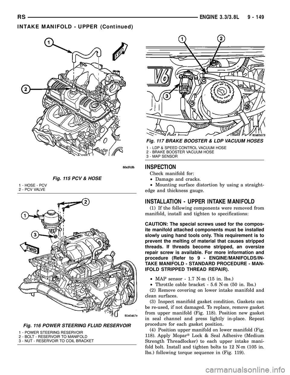
from upper manifold (Fig. 118). Position new gasket
in seal channel and press lightly in-place. Repeat
procedure for each gasket position.
(4) Position upper manifold on lower manifold (Fig.
118). Apply MopartLock & Seal Adhesive (Medium
Strength Threadlocker) to each upper intake mani-
fold bolt. Install and tighten bolts to 12 N´m (105 in.
lbs.) following torque sequence in (Fig. 119).
Fig. 115 PCV & HOSE
1 - HOSE - PCV
2 - P C V VA LV E
Fig. 116 POWER STEERING FLUID RESERVOIR
1 - POWER STEERING RESERVOIR
2 - BOLT - RESERVOIR TO MANIFOLD
3 - NUT - RESERVOIR TO COIL BRACKET
Fig. 117 BRAKE BOOSTER & LDP VACUUM HOSES
1 - LDP & SPEED CONTROL VACUUM HOSE
2 - BRAKE BOOSTER VACUUM HOSE
3 - MAP SENSOR
RSENGINE 3.3/3.8L9 - 149
INTAKE MANIFOLD - UPPER (Continued)