wheel bolts CHRYSLER VOYAGER 2005 Manual PDF
[x] Cancel search | Manufacturer: CHRYSLER, Model Year: 2005, Model line: VOYAGER, Model: CHRYSLER VOYAGER 2005Pages: 2339, PDF Size: 59.69 MB
Page 1411 of 2339

CONDITION POSSIBLE CAUSES CORRECTION
4. Loose lower control arm mounting
bolts at front suspension
crossmember.4. Tighten control arm mounting bolts to
the specified torques.
5. Lower control arm pivot bushing
worn.5. Replace lower control arm pivot
bushing.
6. Loose strut assembly mounting
fasteners at tower or knuckle.6. Tighten strut assembly fasteners to
the specified torque.
7. Power steering fluid hose touching
the body of the vehicle.7. Adjust hose to proper position by
loosening, repositioning, and tightening
attachments to specified torque. Do not
bend tubing.
8. Damaged front suspension
crossmember.8. Replace front suspension
crossmember.
9. Stabilizer bar link ball joints worn. 9. Replace stabilizer bar link.
10. Lug nuts loose. 10. Tighten lug nuts to specifications.
11. Excessive Wheel bearing
free-play.11. Verify correct halfshaft hub nut
torque. Replace hub and bearing if
torque is okay.
12. Internal power steering gear
noise.12. Replace power steering gear.
POPPING NOISE 1. Worn outer tie rod. 1. Check ball joint for free-play;
Replace outer tie rod.
2. Loose inner tie rod. 2. Replace power steering gear.
CHIRP OR SQUEAL
(POWER STEERING
PUMP)1. Loose power steering pump drive
belt.1. Check and adjust power steering
pump drive belt to specifications or
replace automatic tensioner where
applicable. Replace belt if worn or
glazed.
2. Malfuctioning belt auto-tensioner 2. Replace belt auto-tensioner.
WHINE, GROWL, MOAN
OR GROAN (POWER
STEERING PUMP)***1. Low fluid level. 1. Fill power steering fluid reservoir to
proper level and check for leaks (make
sure all air is bled from the system
fluid).
2. Power steering hose touching
vehicle body or frame.2. Adjust hose to proper position by
loosening, repositioning, and tightening
fitting to specified torque. Do not bend
tubing. Replace hose if damaged.
3. Extremely low ambient
temperature.3. Some noise can be expected, but will
go away as vehicle warms. Replace
pump if noise is excessive.
4. Extreme wear of power steering
pump internal components.4. Replace power steering pump and
flush system as necessary.
19 - 4 STEERINGRS
STEERING (Continued)
Page 1415 of 2339
CONDITION POSSIBLE CAUSES CORRECTION
EXCESSIVE STEERING
WHEEL KICKBACK OR
TOO MUCH STEERING
WHEEL FREE PLAY.1. Air in the fluid of the power
steering system.1. Bleed air from system following the the
power steering pump initial operation
service procedure.*
2. Power steering gear loose on
cradle/crossmember.2. Inspect power steering gear mounting
bolts. Replace as necessary. Tighten to the
specified torque.
3. Steering column coupling or
intermediate shaft worn, broken or
loose.3. Replace steering column coupling or
intermediate shaft.
4. Free play in steering column. 4. Check all components of the steering
column and repair or replace as required.
5. Worn lower control arm ball joints. 5. Replace lower control arm ball joints as
required.
6. Loose steering knuckle-to-ball joint
stud pinch bolt.6. Inspect pinch bolt, replace as necessary,
and tighten to specified torque.
7. Front wheel bearing loose or
worn.7. Replace hub and bearing as necessary.
8. Loose outer tie rod end. 8. Replace outer tie rod end that has
excessive free play.
9. Loose inner tie rod. 9. Replace power steering gear.
10. Defective steering gear rotary
valve.10. Replace power steering gear.
* NOTE: Steering shudder can be expected in new
vehicles and vehicles with recent steering system
repairs. Shudder should dissipate after the vehicle
has been driven several weeks.
** NOTE: To evaluate this condition, it may be nec-
essary to disconnect the coupling at the base of the
steering column. Turn the steering wheel and feel or
listen for internal rubbing in steering column. To
avoid damaging the column clockspring, note the
following. Before disconnecting coupling, place
tires in the straight-ahead position and center steer-
ing wheel. Once disconnected, DO NOT rotatesteering wheel more than one revolution in either
direction and place steering wheel in original loca-
tion before reconnecting coupling. If this position is
lost, the steering column clockspring must be
recentered following the procedure found within the
procedure for steering column installation in the
steering column section.
*** NOTE: Increased low speed or stationary steer-
ing effort can be expected if the steering fluid is at
a high temperature. High fluid temperature usually
results from high engine rpm due to trailer towing,
ascending grades, or racing the engine for pro-
longed periods of time.
POWER STEERING FLUID
CONDITION POSSIBLE CAUSES CORRECTION
LOW FLUID LEVEL WITH
VISIBLE LEAK.1. Loose power steering hose
fittings.1. Tighten the fitting to its specified torque.
2. Damaged or missing fitting seal,
gasket, or O-ring.2. Replace as necessary.
3. Power steering component
leaking.3. Repair or replace the leaking component
as required.
19 - 8 STEERINGRS
STEERING (Continued)
Page 1418 of 2339
WARNING: THE AIR BAG SYSTEM IS A SENSITIVE,
COMPLEX ELECTRO-MECHANICAL UNIT. BEFORE
ATTEMPTING TO DIAGNOSE, REMOVE OR INSTALL
THE AIR BAG SYSTEM COMPONENTS YOU MUST
FIRST DISCONNECT AND ISOLATE THE BATTERY
NEGATIVE (GROUND) CABLE. THEN WAIT TWO
MINUTES FOR THE SYSTEM CAPACITOR TO DIS-
CHARGE. FAILURE TO DO SO COULD RESULT IN
ACCIDENTAL DEPLOYMENT OF THE AIR BAG AND
POSSIBLE PERSONAL INJURY. THE FASTENERS,
SCREWS, AND BOLTS, ORIGINALLY USED FOR
THE AIR BAG COMPONENTS, HAVE SPECIAL
COATINGS AND ARE SPECIFICALLY DESIGNED
FOR THE AIR BAG SYSTEM. THEY MUST NEVER
BE REPLACED WITH ANY SUBSTITUTES. ANYTIME
A NEW FASTENER IS NEEDED, REPLACE WITH
THE CORRECT FASTENERS PROVIDED IN THE
SERVICE PACKAGE OR FASTENERS LISTED IN
THE PARTS BOOKS.
WARNING: SAFETY GOGGLES SHOULD BE WORN
AT ALL TIMES WHEN WORKING ON STEERING
COLUMNS.
CAUTION: Disconnect negative (ground) cable from
the battery before servicing any column compo-
nent.
CAUTION: Do not attempt to remove the pivot pins
to disassemble the tilting mechanism. Damage will
occur.
DIAGNOSIS AND TESTING - STEERING
COLUMN
For diagnosis of conditions relating to the steering
column, (Refer to 19 - STEERING - DIAGNOSIS
AND TESTING).
REMOVAL
NOTE: Before proceeding, (Refer to 19 - STEERING/
COLUMN - WARNING)(Refer to 8 - ELECTRICAL/RE-
STRAINTS/DRIVER AIRBAG - REMOVAL).
(1) Make sure the front wheels of the vehicle are
in the STRAIGHT AHEAD position before beginning
the column removal procedure.
(2) Disconnect and isolate the negative (ground)
cable from the battery. Wait at least two minutes for
the airbag system reserve capacitor to discharge
before beginning any steering column, instrument
panel, or airbag system/component service.WARNING: WHEN AN UNDEPLOYED AIRBAG IS TO
BE REMOVED FROM THE VEHICLE, FIRST DISCON-
NECT AND ISOLATE THE BATTERY NEGATIVE
(GROUND) CABLE. ALLOW THE AIRBAG SYSTEM
RESERVE CAPACITOR TO DISCHARGE FOR TWO
MINUTES BEFORE BEGINNING ANY AIRBAG SYS-
TEM OR COMPONENT SERVICE. PERSONAL
INJURY MAY RESULT IF THIS PROCEDURE IS NOT
FOLLOWED.
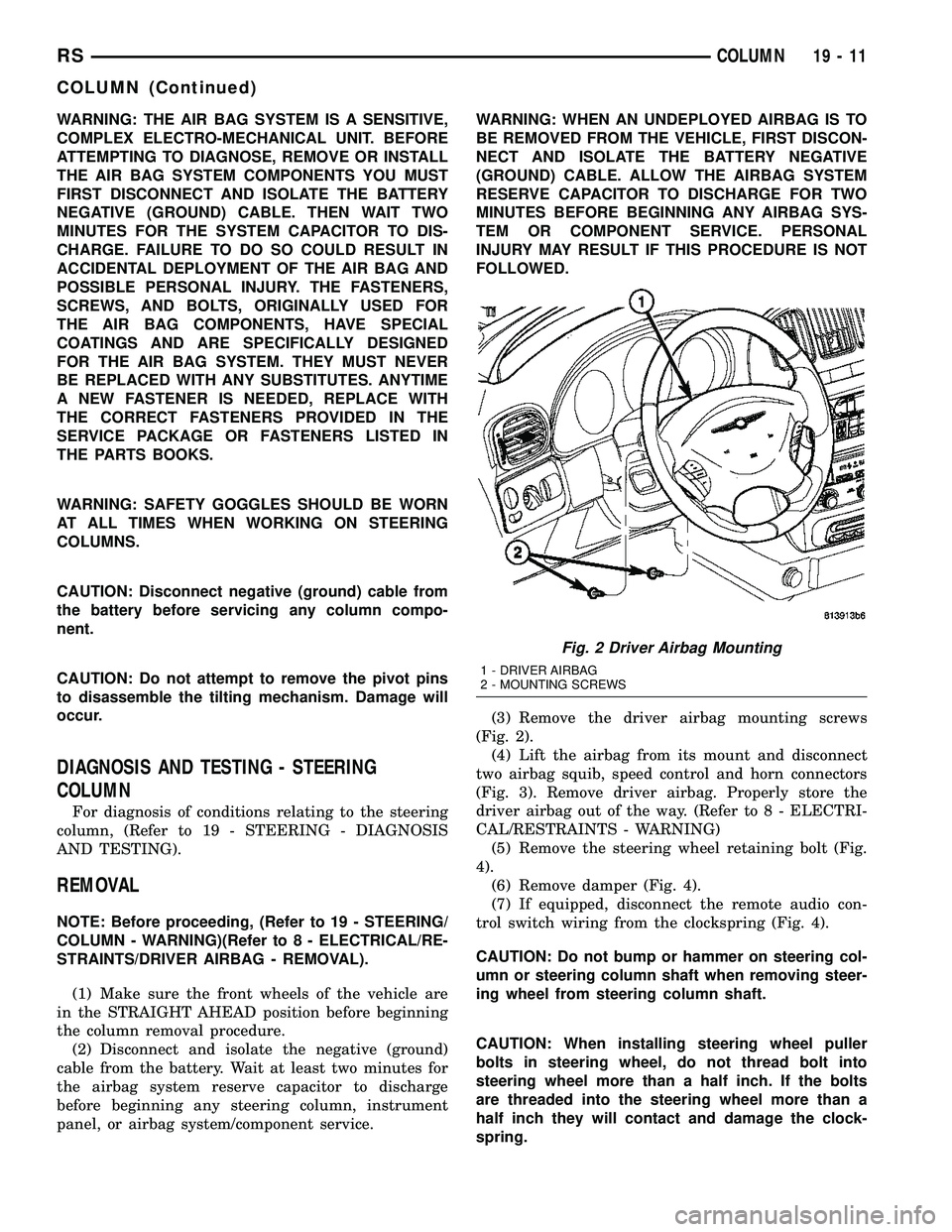
(3) Remove the driver airbag mounting screws
(Fig. 2).
(4) Lift the airbag from its mount and disconnect
two airbag squib, speed control and horn connectors
(Fig. 3). Remove driver airbag. Properly store the
driver airbag out of the way. (Refer to 8 - ELECTRI-
CAL/RESTRAINTS - WARNING)
(5) Remove the steering wheel retaining bolt (Fig.
4).
(6) Remove damper (Fig. 4).
(7) If equipped, disconnect the remote audio con-
trol switch wiring from the clockspring (Fig. 4).
CAUTION: Do not bump or hammer on steering col-
umn or steering column shaft when removing steer-
ing wheel from steering column shaft.
CAUTION: When installing steering wheel puller
bolts in steering wheel, do not thread bolt into
steering wheel more than a half inch. If the bolts
are threaded into the steering wheel more than a
half inch they will contact and damage the clock-
spring.
Fig. 2 Driver Airbag Mounting
1 - DRIVER AIRBAG
2 - MOUNTING SCREWS
RSCOLUMN19-11
COLUMN (Continued)
Page 1431 of 2339

(2) Remove the driver airbag mounting screws
(Fig. 40).
(3) Lift the airbag from its mount and disconnect
two airbag squib, speed control and horn connectors
(Fig. 41). Remove driver airbag. Properly store the
driver airbag out of the way. (Refer to 8 - ELECTRI-
CAL/RESTRAINTS - WARNING)(4) Remove the steering wheel retaining bolt (Fig.
42).
(5) Remove damper (Fig. 42).
(6) If equipped, disconnect the remote audio con-
trol switch wiring from the clockspring (Fig. 42).
CAUTION: Do not bump or hammer on steering col-
umn or steering column shaft when removing steer-
ing wheel from steering column shaft.
CAUTION: When installing steering wheel puller
bolts in steering wheel, do not thread bolt into
steering wheel more than a half inch. If the bolts
are threaded into the steering wheel more than a
half inch they will contact and damage the clock-
spring.
(7) While holding the steering wheel firmly in the
straight-aheadposition, remove the steering wheel
from steering column shaft using a steering wheel
puller (Fig. 43).
(8) Remove the puller from the steering wheel.
(9) If the remote audio switches need removed
from the steering wheel, (Refer to 8 - ELECTRICAL/
AUDIO/REMOTE SWITCHES - REMOVAL).
INSTALLATION
(1) If the remote radio switches need to be
installed on the steering wheel, (Refer to 8 - ELEC-
TRICAL/AUDIO/REMOTE SWITCHES - INSTALLA-
TION).
CAUTION: Do not force steering wheel onto steer-
ing column shaft by driving it on. Pull steering
wheel down onto shaft using only the steering
wheel retaining nut.
Fig. 41 Driver Airbag Wiring Connections
1 - DRIVER AIRBAG
2 - SQUIB CONNECTORS
3 - SPEED CONTROL/HORN WIRING CONNECTOR
4 - CLOCKSPRING
Fig. 42 Steering Wheel Mounting
1 - STEERING WHEEL
2 - REMOTE AUDIO CONTROL WIRING CONNECTOR (IF
EQUIPPED)
3 - RETAINING BOLT
4 - DAMPER
Fig. 43 Steering Wheel Removal
1 - STEERING WHEEL
2 - PULLER
19 - 24 COLUMNRS
STEERING WHEEL (Continued)
Page 1436 of 2339
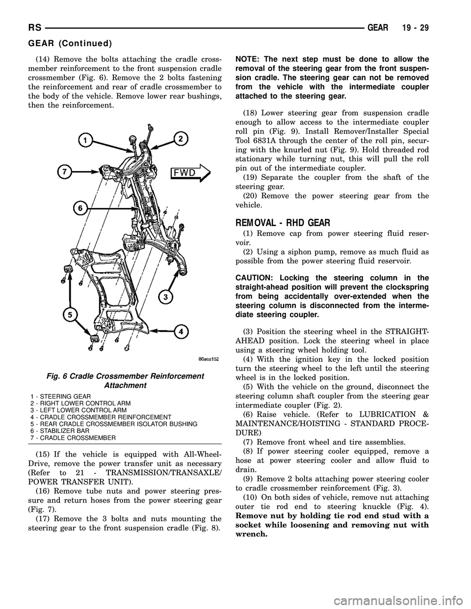
(14) Remove the bolts attaching the cradle cross-
member reinforcement to the front suspension cradle
crossmember (Fig. 6). Remove the 2 bolts fastening
the reinforcement and rear of cradle crossmember to
the body of the vehicle. Remove lower rear bushings,
then the reinforcement.
(15) If the vehicle is equipped with All-Wheel-
Drive, remove the power transfer unit as necessary
(Refer to 21 - TRANSMISSION/TRANSAXLE/
POWER TRANSFER UNIT).
(16) Remove tube nuts and power steering pres-
sure and return hoses from the power steering gear
(Fig. 7).
(17) Remove the 3 bolts and nuts mounting the
steering gear to the front suspension cradle (Fig. 8).NOTE: The next step must be done to allow the
removal of the steering gear from the front suspen-
sion cradle. The steering gear can not be removed
from the vehicle with the intermediate coupler
attached to the steering gear.
(18) Lower steering gear from suspension cradle
enough to allow access to the intermediate coupler
roll pin (Fig. 9). Install Remover/Installer Special
Tool 6831A through the center of the roll pin, secur-
ing with the knurled nut (Fig. 9). Hold threaded rod
stationary while turning nut, this will pull the roll
pin out of the intermediate coupler.
(19) Separate the coupler from the shaft of the
steering gear.
(20) Remove the power steering gear from the
vehicle.
REMOVAL - RHD GEAR
(1) Remove cap from power steering fluid reser-
voir.
(2) Using a siphon pump, remove as much fluid as
possible from the power steering fluid reservoir.
CAUTION: Locking the steering column in the
straight-ahead position will prevent the clockspring
from being accidentally over-extended when the
steering column is disconnected from the interme-
diate steering coupler.
(3) Position the steering wheel in the STRAIGHT-
AHEAD position. Lock the steering wheel in place
using a steering wheel holding tool.
(4) With the ignition key in the locked position
turn the steering wheel to the left until the steering
wheel is in the locked position.
(5) With the vehicle on the ground, disconnect the
steering column shaft coupler from the steering gear
intermediate coupler (Fig. 2).
(6) Raise vehicle. (Refer to LUBRICATION &
MAINTENANCE/HOISTING - STANDARD PROCE-
DURE)
(7) Remove front wheel and tire assemblies.
(8) If power steering cooler equipped, remove a
hose at power steering cooler and allow fluid to
drain.
(9) Remove 2 bolts attaching power steering cooler
to cradle crossmember reinforcement (Fig. 3).
(10) On both sides of vehicle, remove nut attaching
outer tie rod end to steering knuckle (Fig. 4).
Remove nut by holding tie rod end stud with a
socket while loosening and removing nut with
wrench.
Fig. 6 Cradle Crossmember Reinforcement
Attachment
1 - STEERING GEAR
2 - RIGHT LOWER CONTROL ARM
3 - LEFT LOWER CONTROL ARM
4 - CRADLE CROSSMEMBER REINFORCEMENT
5 - REAR CRADLE CROSSMEMBER ISOLATOR BUSHING
6 - STABILIZER BAR
7 - CRADLE CROSSMEMBER
RSGEAR19-29
GEAR (Continued)
Page 1438 of 2339
(12) Remove the lower control arm rear bushing
retainer bolts located on each side of each lower con-
trol arm rear bushing.
NOTE: The bolts fastening the cradle crossmember
reinforcement are of two different thread sizes. Note
the location of the various sizes.
(13) Remove the bolts attaching the cradle cross-
member reinforcement to the front suspension cradle
crossmember (Fig. 6). Remove the 2 bolts fastening
the reinforcement and rear of cradle crossmember to
the body of the vehicle. Remove the reinforcement.
(14) If the vehicle is equipped with All-Wheel-
Drive, remove the power transfer unit (Refer to 21 -
TRANSMISSION/TRANSAXLE/POWER TRANSFER
UNIT - REMOVAL).
(15) Remove the power steering fluid pressure and
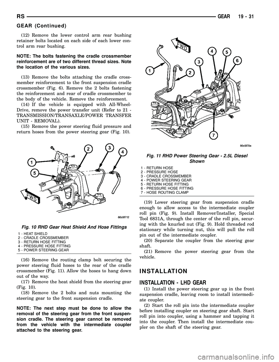
return hoses from the power steering gear (Fig. 10).
(16) Remove the routing clamp bolt securing the
power steering fluid hoses to the rear of the cradle
crossmember (Fig. 11). Allow the hoses to hang down
out of the way.
(17) Remove the heat shield from the steering gear
(Fig. 10).
(18) Remove the 2 bolts and nuts mounting the
steering gear to the front suspension cradle.
NOTE: The next step must be done to allow the
removal of the steering gear from the front suspen-
sion cradle. The steering gear cannot be removed
from the vehicle with the intermediate coupler
attached to the steering gear.(19) Lower steering gear from suspension cradle
enough to allow access to the intermediate coupler
roll pin (Fig. 9). Install Remover/Installer, Special
Tool 6831A, through the center of the roll pin, secur-
ing with the knurled nut (Fig. 9). Hold threaded rod
stationary while turning nut, this will pull the roll
pin out of the intermediate coupler.
(20) Separate the coupler from the steering gear
shaft.
(21) Remove the power steering gear from the
vehicle.
INSTALLATION
INSTALLATION - LHD GEAR
(1) Install the power steering gear up in the front
suspension cradle, leaving room to install intermedi-
ate coupler.
(2) Start the roll pin into the intermediate coupler
before installing coupler on steering gear shaft. Start
roll pin into coupler, using a hammer and tapping it
into the coupler. Then install the intermediate cou-
pler on the shaft of the steering gear.
Fig. 10 RHD Gear Heat Shield And Hose Fittings
1 - HEAT SHIELD
2 - CRADLE CROSSMEMBER
3 - RETURN HOSE FITTING
4 - PRESSURE HOSE FITTING
5 - POWER STEERING GEAR
Fig. 11 RHD Power Steering Gear - 2.5L Diesel
Shown
1 - RETURN HOSE
2 - PRESSURE HOSE
3 - CRADLE CROSSMEMBER
4 - POWER STEERING GEAR
5 - RETURN HOSE FITTING
6 - PRESSURE HOSE FITTING
7 - HOSE ROUTING CLAMP
RSGEAR19-31
GEAR (Continued)
Page 1439 of 2339
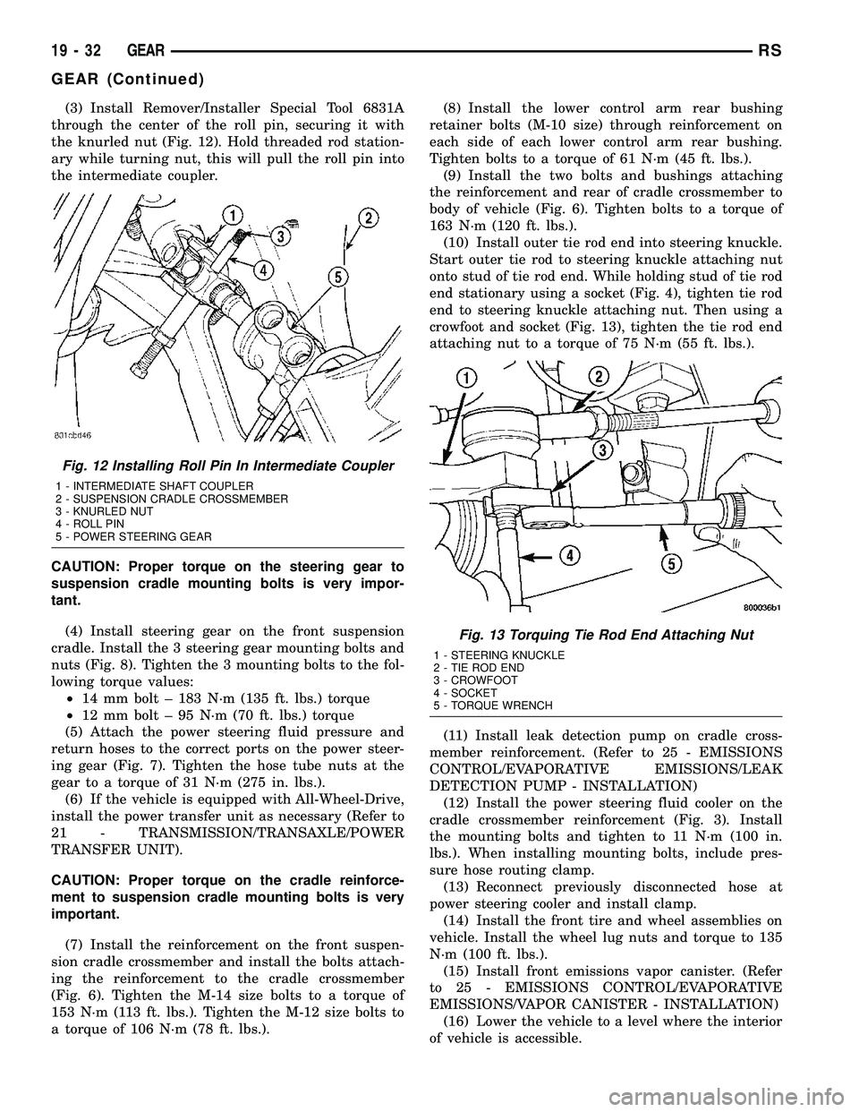
(3) Install Remover/Installer Special Tool 6831A
through the center of the roll pin, securing it with
the knurled nut (Fig. 12). Hold threaded rod station-
ary while turning nut, this will pull the roll pin into
the intermediate coupler.
CAUTION: Proper torque on the steering gear to
suspension cradle mounting bolts is very impor-
tant.
(4) Install steering gear on the front suspension
cradle. Install the 3 steering gear mounting bolts and
nuts (Fig. 8). Tighten the 3 mounting bolts to the fol-
lowing torque values:
²14 mm bolt ± 183 N´m (135 ft. lbs.) torque
²12 mm bolt ± 95 N´m (70 ft. lbs.) torque
(5) Attach the power steering fluid pressure and
return hoses to the correct ports on the power steer-
ing gear (Fig. 7). Tighten the hose tube nuts at the
gear to a torque of 31 N´m (275 in. lbs.).
(6) If the vehicle is equipped with All-Wheel-Drive,
install the power transfer unit as necessary (Refer to
21 - TRANSMISSION/TRANSAXLE/POWER
TRANSFER UNIT).
CAUTION: Proper torque on the cradle reinforce-
ment to suspension cradle mounting bolts is very
important.
(7) Install the reinforcement on the front suspen-
sion cradle crossmember and install the bolts attach-
ing the reinforcement to the cradle crossmember
(Fig. 6). Tighten the M-14 size bolts to a torque of
153 N´m (113 ft. lbs.). Tighten the M-12 size bolts to
a torque of 106 N´m (78 ft. lbs.).(8) Install the lower control arm rear bushing
retainer bolts (M-10 size) through reinforcement on
each side of each lower control arm rear bushing.
Tighten bolts to a torque of 61 N´m (45 ft. lbs.).
(9) Install the two bolts and bushings attaching
the reinforcement and rear of cradle crossmember to
body of vehicle (Fig. 6). Tighten bolts to a torque of
163 N´m (120 ft. lbs.).
(10) Install outer tie rod end into steering knuckle.
Start outer tie rod to steering knuckle attaching nut
onto stud of tie rod end. While holding stud of tie rod
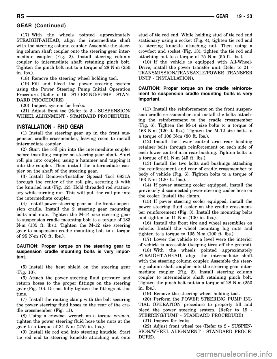
end stationary using a socket (Fig. 4), tighten tie rod
end to steering knuckle attaching nut. Then using a
crowfoot and socket (Fig. 13), tighten the tie rod end
attaching nut to a torque of 75 N´m (55 ft. lbs.).
(11) Install leak detection pump on cradle cross-
member reinforcement. (Refer to 25 - EMISSIONS
CONTROL/EVAPORATIVE EMISSIONS/LEAK
DETECTION PUMP - INSTALLATION)
(12) Install the power steering fluid cooler on the
cradle crossmember reinforcement (Fig. 3). Install
the mounting bolts and tighten to 11 N´m (100 in.
lbs.). When installing mounting bolts, include pres-
sure hose routing clamp.
(13) Reconnect previously disconnected hose at
power steering cooler and install clamp.
(14) Install the front tire and wheel assemblies on
vehicle. Install the wheel lug nuts and torque to 135
N´m (100 ft. lbs.).
(15) Install front emissions vapor canister. (Refer
to 25 - EMISSIONS CONTROL/EVAPORATIVE
EMISSIONS/VAPOR CANISTER - INSTALLATION)
(16) Lower the vehicle to a level where the interior
of vehicle is accessible.
Fig. 12 Installing Roll Pin In Intermediate Coupler
1 - INTERMEDIATE SHAFT COUPLER
2 - SUSPENSION CRADLE CROSSMEMBER
3 - KNURLED NUT
4 - ROLL PIN
5 - POWER STEERING GEAR
Fig. 13 Torquing Tie Rod End Attaching Nut
1 - STEERING KNUCKLE
2 - TIE ROD END
3 - CROWFOOT
4 - SOCKET
5 - TORQUE WRENCH
19 - 32 GEARRS
GEAR (Continued)
Page 1440 of 2339
(17) With the wheels pointed approximately
STRAIGHT-AHEAD, align the intermediate shaft
with the steering column coupler. Assemble the steer-
ing column shaft coupler onto the steering gear inter-
mediate coupler (Fig. 2). Install steering column
coupler to intermediate shaft retaining pinch bolt.
Tighten the pinch bolt nut to a torque of 28 N´m (250
in. lbs.).
(18) Remove the steering wheel holding tool.
(19) Fill and bleed the power steering system
using the Power Steering Pump Initial Operation
Procedure. (Refer to 19 - STEERING/PUMP - STAN-
DARD PROCEDURE)
(20) Inspect system for leaks.
(21) Adjust front toe (Refer to 2 - SUSPENSION/
WHEEL ALIGNMENT - STANDARD PROCEDURE).
INSTALLATION - RHD GEAR
(1) Install the steering gear up in the front sus-
pension cradle crossmember, leaving room to install
intermediate coupler.
(2) Start the roll pin into the intermediate coupler
before installing coupler on steering gear shaft. Start
roll pin into coupler, using a hammer and tapping it
into the coupler. Then install the intermediate cou-
pler on the shaft of the steering gear.
(3) Install Remover/Installer Special Tool 6831A
through the center of the roll pin, securing it with
the knurled nut (Fig. 12). Hold threaded rod station-
ary while turning nut. This will pull the roll pin into
the intermediate coupler.
(4) Install power steering gear on the front suspen-
sion cradle. Install the 2 steering gear mounting
bolts and nuts. Tighten the M-14 size steering gear
to suspension cradle mounting bolt to a torque of 183
N´m (135 ft. lbs.). Tighten the M-12 size steering
gear to suspension cradle mounting bolt to a torque
of 95 N´m (70 ft. lbs.).
CAUTION: Proper torque on the steering gear to
suspension cradle mounting bolts is very impor-
tant.
(5) Install the heat shield on the steering gear
(Fig. 10).
(6) Attach the power steering fluid pressure and
return hoses to the proper fittings on the steering
gear (Fig. 10). Do not fully tighten the fittings at this
time.
(7) Install the routing clamp with the bolt securing
the power steering fluid hoses to the rear of the cra-
dle crossmember (Fig. 11).
(8) Using a crowfoot wrench on a torque wrench,
tighten the power steering fluid hose tube nuts at the
gear to a torque of 31 N´m (275 in. lbs.).
(9) Install tie rod end into steering knuckle. Start
tie rod end to steering knuckle attaching nut ontostud of tie rod end. While holding stud of tie rod end
stationary using a socket (Fig. 4), tighten tie rod end
to steering knuckle attaching nut. Then using a
crowfoot and socket (Fig. 13), tighten the tie rod end
attaching nut to a torque of 75 N´m (55 ft. lbs.).
(10) If the vehicle is equipped with All-Wheel-
Drive, install the power transfer unit (Refer to 21 -
TRANSMISSION/TRANSAXLE/POWER TRANSFER
UNIT - INSTALLATION).
CAUTION: Proper torque on the cradle reinforce-
ment to suspension cradle mounting bolts is very
important.
(11) Install the reinforcement on the front suspen-
sion cradle crossmember and install the bolts attach-
ing the reinforcement to the cradle crossmember
(Fig. 6). Tighten the M-14 size bolts to a torque of
163 N´m (120 ft. lbs.). Tighten the M-12 size bolts to
a torque of 108 N´m (80 ft. lbs.).
(12) Install the lower control arm rear bushing
retainer bolts through reinforcement on each side of
each lower control arm rear bushing. Tighten bolts to
a torque of 61 N´m (45 ft. lbs.).
(13) Install the two bolts and bushings attaching
the reinforcement and rear of cradle crossmember to
body of vehicle (Fig. 6). Tighten bolts to a torque of
163 N´m (120 ft. lbs.).
(14) If power steering cooler equipped, install the
previously disconnected power steering cooler hose on
the cooler. Install the clamp.
(15) If power steering cooler equipped, install the
power steering fluid cooler on the cradle crossmem-
ber reinforcement (Fig. 3). Install the mounting bolts
and tighten to 11 N´m (100 in. lbs.).
(16) Install the front tire and wheel assemblies on
vehicle. Install the wheel mounting lug nuts and
tighten to a torque to 135 N´m (100 ft. lbs.).
(17) Lower the vehicle to a level were the interior
of vehicle is accessible (keeping tires off the ground).
(18) With the wheels pointed approximately
STRAIGHT-AHEAD, align the intermediate shaft
with the steering column coupler. Assemble the steer-
ing column shaft coupler onto the steering gear inter-
mediate coupler (Fig. 2). Install steering column
coupler to intermediate shaft retaining pinch bolt.
Tighten the pinch bolt nut to a torque of 28 N´m (250
in. lbs.).
(19) Remove the steering wheel holding tool.
(20) Perform the POWER STEERING PUMP INI-
TIAL OPERATION procedure to properly fill and
bleed the power steering system. (Refer to 19 -
STEERING/PUMP - STANDARD PROCEDURE)
(21) Inspect for leaks.
(22) Adjust front wheel toe (Refer to 2 - SUSPEN-
SION/WHEEL ALIGNMENT - STANDARD PROCE-
DURE).
RSGEAR19-33
GEAR (Continued)
Page 1445 of 2339
Read the fluid level through the side of the power
steering fluid reservoir. The fluid level should indi-
cateªFILL RANGEºwhen the fluid is at a temper-
ature of approximately 21ÉC to 27ÉC (70ÉF to 80ÉF).
(1) Wipe the filler cap and area clean, then remove
the cap.
(2) Fill the fluid reservoir to the proper level and
let the fluid settle for at least two (2) minutes.
(3) Start the engine and let run for a few seconds,
then turn the engine off.
(4) Add fluid if necessary. Repeat the above steps
until the fluid level remains constant after running
the engine.
(5) Raise the front wheels off the ground.
(6) Start the engine.
(7) Slowly turn the steering wheel right and left,
lightly contacting the wheel stops.
(8) Add fluid if necessary.
(9) Lower the vehicle, then turn the steering wheel
slowly from lock-to-lock.
(10) Stop the engine. Check the fluid level and
refill as required.
(11) If the fluid is extremely foamy, allow the vehi-
cle to stabilize a few minutes, then repeat the above
procedure.
REMOVAL
REMOVAL - PUMP (2.4L ENGINE)
(1) Remove the (-) negative battery cable from the
battery and isolate cable.
(2) Remove the cap from the power steering fluid
reservoir.
(3) Using a siphon pump, remove as much power
steering fluid as possible from the power steering
fluid reservoir.
(4) Raise the vehicle on jack stands or centered on
a frame contact type hoist. See Hoisting in Lubrica-
tion and Maintenance.
(5) Disconnect the oxygen sensor wiring harness
from the vehicle wiring harness at the rear engine
mount bracket.
NOTE: The exhaust system needs to be removed
from the engine to allow for an area to remove the
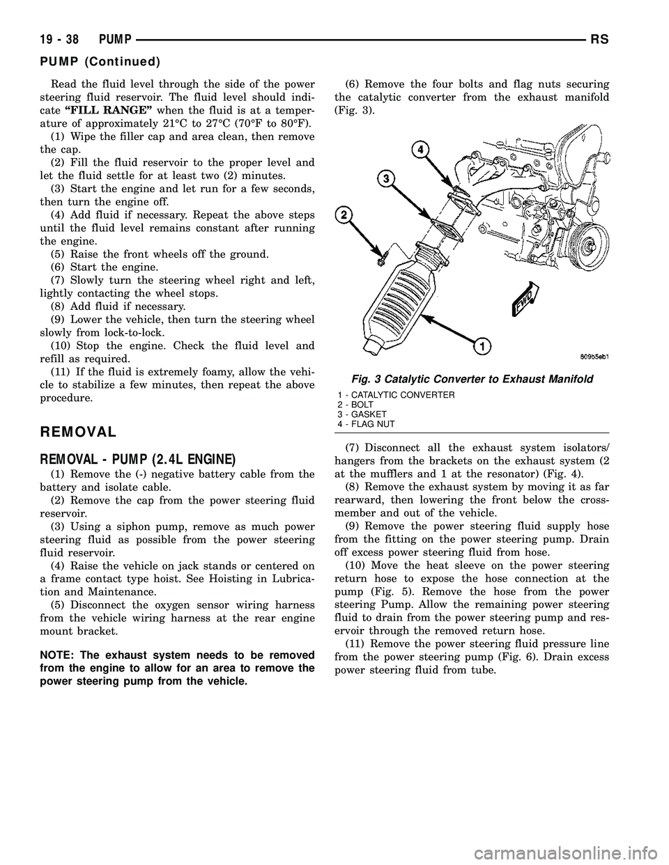
power steering pump from the vehicle.(6) Remove the four bolts and flag nuts securing
the catalytic converter from the exhaust manifold
(Fig. 3).
(7) Disconnect all the exhaust system isolators/
hangers from the brackets on the exhaust system (2
at the mufflers and 1 at the resonator) (Fig. 4).
(8) Remove the exhaust system by moving it as far
rearward, then lowering the front below the cross-
member and out of the vehicle.
(9) Remove the power steering fluid supply hose
from the fitting on the power steering pump. Drain
off excess power steering fluid from hose.
(10) Move the heat sleeve on the power steering
return hose to expose the hose connection at the
pump (Fig. 5). Remove the hose from the power
steering Pump. Allow the remaining power steering
fluid to drain from the power steering pump and res-
ervoir through the removed return hose.
(11) Remove the power steering fluid pressure line
from the power steering pump (Fig. 6). Drain excess
power steering fluid from tube.
Fig. 3 Catalytic Converter to Exhaust Manifold
1 - CATALYTIC CONVERTER
2 - BOLT
3 - GASKET
4 - FLAG NUT
19 - 38 PUMPRS
PUMP (Continued)
Page 1472 of 2339
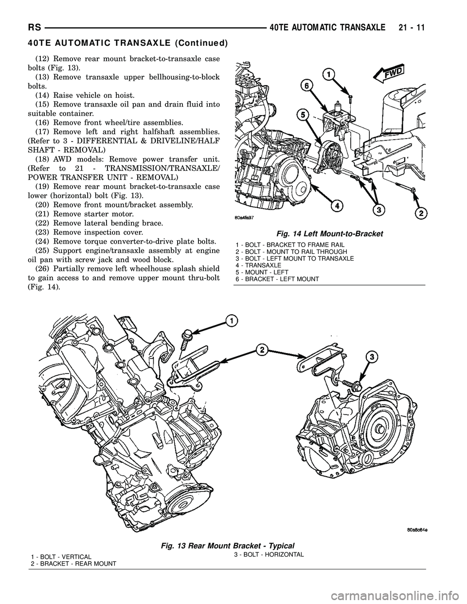
(12) Remove rear mount bracket-to-transaxle case
bolts (Fig. 13).
(13) Remove transaxle upper bellhousing-to-block
bolts.
(14) Raise vehicle on hoist.
(15) Remove transaxle oil pan and drain fluid into
suitable container.
(16) Remove front wheel/tire assemblies.
(17) Remove left and right halfshaft assemblies.
(Refer to 3 - DIFFERENTIAL & DRIVELINE/HALF
SHAFT - REMOVAL)
(18) AWD models: Remove power transfer unit.
(Refer to 21 - TRANSMISSION/TRANSAXLE/
POWER TRANSFER UNIT - REMOVAL)
(19) Remove rear mount bracket-to-transaxle case
lower (horizontal) bolt (Fig. 13).
(20) Remove front mount/bracket assembly.
(21) Remove starter motor.
(22) Remove lateral bending brace.
(23) Remove inspection cover.
(24) Remove torque converter-to-drive plate bolts.
(25) Support engine/transaxle assembly at engine
oil pan with screw jack and wood block.
(26) Partially remove left wheelhouse splash shield
to gain access to and remove upper mount thru-bolt
(Fig. 14).
Fig. 13 Rear Mount Bracket - Typical
1 - BOLT - VERTICAL
2 - BRACKET - REAR MOUNT3 - BOLT - HORIZONTAL
Fig. 14 Left Mount-to-Bracket
1 - BOLT - BRACKET TO FRAME RAIL
2 - BOLT - MOUNT TO RAIL THROUGH
3 - BOLT - LEFT MOUNT TO TRANSAXLE
4 - TRANSAXLE
5 - MOUNT - LEFT
6 - BRACKET - LEFT MOUNT
RS40TE AUTOMATIC TRANSAXLE21-11
40TE AUTOMATIC TRANSAXLE (Continued)