3 row bench CHRYSLER VOYAGER 2005 Service Manual
[x] Cancel search | Manufacturer: CHRYSLER, Model Year: 2005, Model line: VOYAGER, Model: CHRYSLER VOYAGER 2005Pages: 2339, PDF Size: 59.69 MB
Page 488 of 2339
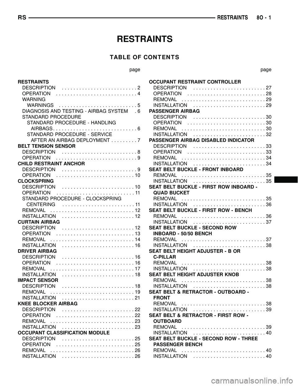
RESTRAINTS
TABLE OF CONTENTS
page page
RESTRAINTS
DESCRIPTION..........................2
OPERATION............................4
WARNING
WARNINGS...........................5
DIAGNOSIS AND TESTING - AIRBAG SYSTEM . 6
STANDARD PROCEDURE
STANDARD PROCEDURE - HANDLING
AIRBAGS.............................6
STANDARD PROCEDURE - SERVICE
AFTER AN AIRBAG DEPLOYMENT.........7
BELT TENSION SENSOR
DESCRIPTION..........................8
OPERATION............................9
CHILD RESTRAINT ANCHOR
DESCRIPTION..........................9
OPERATION...........................10
CLOCKSPRING
DESCRIPTION.........................10
OPERATION...........................11
STANDARD PROCEDURE - CLOCKSPRING
CENTERING.........................11
REMOVAL.............................12
INSTALLATION.........................12
CURTAIN AIRBAG
DESCRIPTION.........................12
OPERATION...........................13
REMOVAL.............................14
INSTALLATION.........................16
DRIVER AIRBAG
DESCRIPTION.........................16
OPERATION...........................16
REMOVAL.............................17
INSTALLATION.........................18
IMPACT SENSOR
DESCRIPTION.........................18
REMOVAL.............................19
INSTALLATION.........................21
KNEE BLOCKER AIRBAG
DESCRIPTION.........................22
OPERATION...........................22
REMOVAL.............................23
INSTALLATION.........................23
OCCUPANT CLASSIFICATION MODULE
DESCRIPTION.........................25
OPERATION...........................25
REMOVAL.............................26
INSTALLATION.........................26OCCUPANT RESTRAINT CONTROLLER
DESCRIPTION.........................27
OPERATION...........................28
REMOVAL.............................29
INSTALLATION.........................29
PASSENGER AIRBAG
DESCRIPTION.........................30
OPERATION...........................30
REMOVAL.............................30
INSTALLATION.........................32
PASSENGER AIRBAG DISABLED INDICATOR
DESCRIPTION.........................33
OPERATION...........................33
REMOVAL.............................34
INSTALLATION.........................34
SEAT BELT BUCKLE - FRONT INBOARD
REMOVAL.............................35
INSTALLATION.........................35
SEAT BELT BUCKLE - FIRST ROW INBOARD -
QUAD BUCKET
REMOVAL.............................35
INSTALLATION.........................36
SEAT BELT BUCKLE - FIRST ROW - BENCH
REMOVAL.............................36
INSTALLATION.........................37
SEAT BELT BUCKLE - SECOND ROW
INBOARD - 50/50 BENCH
REMOVAL.............................37
INSTALLATION.........................38
SEAT BELT HEIGHT ADJUSTER-BOR
C-PILLAR
REMOVAL.............................38
INSTALLATION.........................38
SEAT BELT HEIGHT ADJUSTER KNOB
REMOVAL.............................38
INSTALLATION.........................38
SEAT BELT & RETRACTOR - OUTBOARD -
FRONT
REMOVAL.............................38
INSTALLATION.........................39
SEAT BELT & RETRACTOR - FIRST ROW -
OUTBOARD
REMOVAL.............................39
INSTALLATION.........................40
SEAT BELT BUCKLE - SECOND ROW - THREE
PASSENGER BENCH
REMOVAL.............................40
INSTALLATION.........................40
RSRESTRAINTS8O-1
Page 523 of 2339

(3) Remove the hinge retaining bolts under the
cushion cover side panel (Fig. 42).
(4) Gently lift hinge upwards to free buckle from
between the cushion frame and the hinge itself (Fig.
43).(5) Remove buckle half from seat.
INSTALLATION
QUAD BUCKET
(1) Place buckle into position.
(2) Install bolt attaching seat belt buckle to seat
track. Torque bolt to 39 N´m (29 ft. lbs.).
(3) Install recliner bracket onto the seat.
(4) Install bolts attaching recliner bracket to seat
cushion.
(5) Install side cover from seat.
(6) Install screws attaching inboard side cover to
seat cushion.
(7) Install seat into position.
QUAD BUCKET - FOLD IN FLOOR
(1) Gently lift hinge upwards and place buckle in
between the cushion frame and the hinge itself (Fig.
43).
(2) Install the hinge retaining bolts under the
cushion cover side panel (Fig. 42).
(3) Install the hinge cover retaining screw and
hinge cover.
SEAT BELT BUCKLE - FIRST
ROW - BENCH
REMOVAL
(1) Remove seat from vehicle.
(2) Remove bolt attaching inboard seat belt buckle
to seat frame (Fig. 44).
(3) Remove belt from seat.
Fig. 42 1ST ROW INBOARD BUCKLE RETAINING
BOLTS - FOLD IN FLOOR
1 - SEAT BELT BUCKLE
2 - SEAT BACK INBOARD HINGE
3 - SEAT RISER
4 - INBOARD HINGE RETAINING BOLTS
5 - SEAT CUSHION COVER SIDE PANEL
Fig. 43 1ST ROW INBOARD BUCKLE - FOLD IN
FLOOR
1 - SEAT BACK HINGE
2 - SEAT BELT BUCKLE
3 - SEAT CUSHION FRAME
Fig. 44 SEAT BELT BUCKLE - FIRST ROW - BENCH
1 - ANCHOR BOLT
2 - TWO (2) PASS REAR SEAT BELT BUCKLE
3 - RISER
4 - REAR FRAME
8O - 36 RESTRAINTSRS
SEAT BELT BUCKLE - FIRST ROW INBOARD - QUAD BUCKET (Continued)
Page 524 of 2339

INSTALLATION
(1) Place seat belt into position to the seat.
(2) Install bolt attaching inboard seat belt buckle
to seat frame. Tighten all seat belt anchor bolts to 39
N´m (29 ft. lbs.) torque.
(3) Install seat into position.
SEAT BELT BUCKLE - SECOND
ROW INBOARD - 50/50 BENCH
REMOVAL
SECOND ROW 50/50 BENCH
(1) Open rear liftgate.
(2) Pull handle #1 and fold seat back forward.
(3) Pull handle #2, and lift seat bottom up.
(4) Pull #3 strap and remove seat from latching
area.
(5) While looking at the bottom of the seat, locate
retaining bolt on the left side of the seat riser.
Remove retaining bolt from seat riser (Fig. 45).
(6) Pull belt through seat cushion.
SECOND ROW - FOLD IN FLOOR
(1) Fold in floor the seat not having the buckle
replaced.(2) Remove the hinge cover retaining screw (Fig.
46).
(3) Pull hinge cover out just far enough to gain
access to buckle retaining nut (Fig. 47). Remove nut
and slide buckle out from under cushion cover side
panel.
Fig. 45 SEAT BELT BUCKLE - SECOND ROW
INBOARD - 50/50 BENCH
1 - SEAT BELT BUCKLE
2 - BUCKLE RETAINING BOLT
3 - 50/50 SPLIT BENCH RISER
4 - BOTTOM OF SEAT CUSHION
Fig. 46 FIRST ROW BUCKLE - INBOARD - COVER
RETAINING SCREW
1 - SEAT BELT BUCKLE
2 - HINGE COVER
3 - HINGE COVER RETAINING SCREW
4 - CUSHION COVER SIDE PANEL
Fig. 47 FIRST ROW BUCKLE - INBOARD -
RETAINING NUT
1 - SEAT BELT BUCKLE
2 - HINGE COVER
3 - SEAT BELT BUCKLE RETAINING NUT
4 - CUSHION COVER SIDE PANEL
RSRESTRAINTS8O-37
SEAT BELT BUCKLE - FIRST ROW - BENCH (Continued)
Page 525 of 2339

INSTALLATION
(1) Push belt through seat cushion.
(2) While looking at the bottom of the seat, locate
retaining bolt hole on the left side of the seat riser.
Install retaining bolt into seat riser (Fig. 45). Torque
anchor bolt to 39 N´m (29 ft. lbs.).
(3) Place seat into track and on front anchors.
(4) Pull #3 strap and install seat onto latching
area.
(5) Pull seat assembly down firmly and snap into
track.
(6) Pull handle #1 and fold seat back rearward.
(7) Close rear liftgate.
SEAT BELT HEIGHT
ADJUSTER-BORC-PILLAR
REMOVAL
(1) Remove turning loop retaining bolt.
(2) Remove B or C-pillar trim cover.
(3) Remove two screws attaching shoulder belt
height adjuster to pillar.
(4) Remove height adjuster from vehicle.
INSTALLATION
(1) Place height adjuster into position.
(2) Install screws attaching shoulder belt height
adjuster to pillar.
(3) Install B or C-pillar trim cover.
(4) Install turning loop to height adjuster. Torque
anchor bolt to 39 N´m (29 ft. lbs.).
SEAT BELT HEIGHT
ADJUSTER KNOB
REMOVAL
(1) Disengage clips attaching clam shell cover to
seat belt turning loop and open cover.
(2) Using a trim tool (special tool #C-4755), gently
pry knob from seat belt height adjuster.
INSTALLATION
(1) Place seat belt height adjuster knob in position
on height adjuster.
(2) Firmly push knob on until retainers engage.
(3) Reinstall turning loop clam shell cover.
(4) Verify seat belt operation. Make sure it moves
through loop without binding.
SEAT BELT & RETRACTOR -
OUTBOARD - FRONT
REMOVAL
(1) Open door.
(2) Move seat all the way forward.
(3) Open hood.
(4) Disconnect and isolate the battery negative
cable.
(5)
WARNING: Wait two minutes for the airbag system
reserve capacitor to discharge before beginning
any airbag system or component service. Failure to
do so may result in accidental airbag deployment,
personal injury or death.
(6) Remove shoulder harness height adjuster knob
by pulling it straight away from adjuster (Fig. 48).
(7) Remove cover from seat belt turning loop (Fig.
48).
(8) Remove bolt attaching turning loop to shoulder
belt height adjuster (Fig. 48).
(9) Remove upper B-pillar trim cover (Fig. 48).
NOTE: If equipped with the Occupant Classification
System (OCS), there is a Belt Tension Sensor
located on the lower seat belt anchor on the pas-
senger front seat belt.
Fig. 48 SEAT BELT - OUTBOARD FRONT
1 - B-PILLAR TRIM LOWER
2 - BELT
3 - B-PILLAR TRIM UPPER
4 - HEIGHT ADJUSTER
5 - KNOB
6 - B-PILLAR TRIM LOWER
7 - FLOOR ANCHOR
8 - FLOOR ANCHOR
9 - 30É OUTBOARD
10 - RETRACTOR
8O - 38 RESTRAINTSRS
SEAT BELT BUCKLE - SECOND ROW INBOARD - 50/50 BENCH (Continued)
Page 527 of 2339

accessible from the rear after the D-pillar trim is
removed.
(10) Remove quarter trim bolster.
(11) Remove quarter trim panel screws.
(12) Remove quarter trim panel.
(13) Remove first row seat belt and retractor
retaining bolt.
(14) Remove first row seat belt and retractor from
vehicle.
INSTALLATION
(1) Install first row seat belt and retractor. Torque
bolt to 39 N´m (29 ft. lbs.).
(2) Install quarter trim panel.
(3) Install quarter trim panel screws.
(4) Install quarter trim bolster.
(5) Connect speaker connector. The left side has
the speaker mounted in the D-pillar trim cover and
the right side will have the speaker mounted in the
rear of the quarter trim panel, but the connector is
accessible from the rear after the D-pillar trim is
removed.
(6) Install D-pillar trim cover.
(7) Install second seat belt lower anchor bolt.
Torque bolt to 39 N´m (29 ft. lbs.).
(8) Install second seat belt upper turning loop
anchor bolt. Torque bolt to 39 N´m (29 ft. lbs.).
(9) Install upper liftgate trim.
(10) Install liftgate sill plate.
(11) Install first row seat belt upper turning loop
anchor bolt. Torque bolt to 39 N´m (29 ft. lbs.).
(12) Install first row seat belt lower anchor bolt.
Torque bolt to 39 N´m (29 ft. lbs.).
(13) Install first and second row seats.
SEAT BELT BUCKLE - SECOND
ROW - THREE PASSENGER
BENCH
REMOVAL
(1) Remove bolt attaching seat belt buckle to seat
rear frame rail (Fig. 50).
(2) Remove seat belt buckle from seat.
INSTALLATION
(1) Place seat belt buckle in position on seat.
(2) Install bolt to attach seat belt buckle to seat
rear frame rail. Tighten all seat belt bolts to 39 N´m
(29 ft. lbs.) torque.
SEAT BELT & RETRACTOR -
SECOND ROW - RIGHT
OUTBOARD
REMOVAL
(1) Remove first and second row seats.
(2) Remove first row seat belt lower anchor bolt.
(3) Remove first row seat belt upper anchor bolt.
(4) Remove liftgate sill plate.
(5) Remove upper liftgate trim.
(6) Remove second seat belt lower anchor bolt.
(7) Remove second seat belt upper anchor bolt.
(8) Remove D-pillar trim cover.
(9) Disconnect speaker connector. The left side has
the speaker mounted in the D-pillar trim cover and
the right side will have the speaker mounted in the
rear of the quarter trim panel, but the connector is
accessible from the rear after the D-pillar trim is
removed.
(10) Remove quarter trim bolster.
(11) Remove quarter trim panel screws.
(12) Remove quarter trim panel.
(13) Remove retractor retaining bolt.
(14) Remove second row seat belt and retractor.
INSTALLATION
(1) Install second row seat belt and retractor.
Torque bolt to 39 N´m (29 ft. lbs.).
(2) Install quarter trim panel.
(3) Install quarter trim panel screws.
(4) Install quarter trim bolster.
(5) Connect speaker connector. The left side has
the speaker mounted in the D-pillar trim cover and
Fig. 50 SEAT BELT BUCKLE - SECOND ROW -
THREE PASSENGER BENCH
1 - ANCHOR BOLT
2 - SEAT BELTS
3 - ANCHOR
4 - RISER
8O - 40 RESTRAINTSRS
SEAT BELT & RETRACTOR - FIRST ROW - OUTBOARD (Continued)
Page 1881 of 2339

SEATS
TABLE OF CONTENTS
page page
CHILD SEAT MODULE, BENCH SEAT
REMOVAL............................104
INSTALLATION
INSTALLATION......................105
SYNCHRONIZING CABLE ADJUSTMENT . . 105
QUAD CHILD SEAT
REMOVAL............................106
INSTALLATION........................106
HEADREST
REMOVAL............................106
INSTALLATION........................106
HEADREST SLEEVE
REMOVAL............................107
INSTALLATION........................107
RECLINER HANDLE
REMOVAL............................108
INSTALLATION........................108
ARMREST
REMOVAL............................108
INSTALLATION........................108
FRONT SEAT
REMOVAL............................108
INSTALLATION........................110
FRONT SEAT BACK
REMOVAL............................111
INSTALLATION........................111
FRONT SEAT BACK ASSIST STRAP
REMOVAL............................112
INSTALLATION........................112
FRONT SEAT BACK PANEL
REMOVAL............................112
INSTALLATION........................113
FRONT SEAT BACK COVER
REMOVAL............................113
INSTALLATION........................116
FRONT SEAT CUSHION
REMOVAL............................117
INSTALLATION........................118
FRONT SEAT CUSHION - OCS
REMOVAL............................119
INSTALLATION........................120
FRONT SEAT CUSHION SIDE COVER
REMOVAL............................120
INSTALLATION........................121
FRONT SEAT CUSHION SIDE COVER - OCS
REMOVAL............................121
INSTALLATION........................122
FRONT SEAT RISER - MANUAL - OCS
REMOVAL............................123INSTALLATION........................123
FRONT SEAT TRACK POWER ADJUSTER
REMOVAL............................124
INSTALLATION........................124
FRONT SEAT TRACK ADJUSTER/POWER -
OCS
REMOVAL............................124
INSTALLATION........................125
FRONT SEAT TRACK MANUAL ADJUSTER
REMOVAL............................125
INSTALLATION........................126
FRONT SEAT TRACK ADJUSTER/MANUAL -
OCS
REMOVAL............................126
INSTALLATION........................128
FRONT SEAT TRACK - REAR COVER
REMOVAL............................128
INSTALLATION........................128
FRONT SEAT TRACK REAR COVER - OCS
REMOVAL............................129
INSTALLATION........................129
ARMREST - SECOND ROW - FOLD-IN-FLOOR
REMOVAL............................130
INSTALLATION........................130
ARMREST ROTATING ASSEMBLY - SECOND
ROW - FOLD-IN-FLOOR
REMOVAL............................130
INSTALLATION........................130
HEADREST SLEEVE - SECOND ROW -
FOLD-IN-FLOOR
REMOVAL............................131
INSTALLATION........................131
SEAT - SECOND ROW - FOLD-IN-FLOOR
REMOVAL............................132
INSTALLATION........................132
SEAT BACK COVER/FOAM - SECOND ROW -
FOLD-IN-FLOOR
REMOVAL............................133
INSTALLATION........................133
SEAT BACK FRAME - SECOND ROW -
FOLD-IN-FLOOR
REMOVAL............................134
INSTALLATION........................134
SEAT BACK PANEL - SECOND ROW -FOLD-IN-
FLOOR
REMOVAL............................134
INSTALLATION........................134
23 - 102 SEATSRS
Page 1882 of 2339

SEAT BASE RISER - SECOND ROW - FOLD-IN-
FLOOR
REMOVAL............................134
INSTALLATION........................135
SEAT CUSHION COVER/FOAM -SECOND ROW
- FOLD-IN-FLOOR
REMOVAL............................136
INSTALLATION........................136
SEAT RECLINER/FORWARD FOLDING
MECHANISM -SECOND ROW -FOLD-IN-
FLOOR
REMOVAL............................137
INSTALLATION........................137
SEAT CUSHION SIDE SHIELD - SECOND ROW
- FOLD-IN-FLOOR
REMOVAL............................138
INSTALLATION........................138
SEAT GAS STRUT - SECOND ROW - FOLD-IN-
FLOOR
REMOVAL............................138
INSTALLATION........................139
SEAT PROP ROD - SECOND ROW - FOLD-IN-
FLOOR
REMOVAL............................139
INSTALLATION........................140
BUCKET SEAT BACK - QUAD BUCKET
REMOVAL............................140
INSTALLATION........................141
QUAD SEAT CUSHION
REMOVAL............................141
INSTALLATION........................141
QUAD BUCKET SEAT SIDE SHIELD/CUP
HOLDER
REMOVAL............................141
INSTALLATION........................142
QUAD BUCKET SEAT SIDE SHIELD - NO CUP
HOLDER
REMOVAL............................143
INSTALLATION........................143
QUAD BUCKET SEAT RISER
REMOVAL............................143
INSTALLATION........................143
BENCH SEAT BACK PANEL
REMOVAL............................143
INSTALLATION........................144
SEAT CUSHION COVER - QUAD BUCKET,
50/50 SPLIT, BENCH
REMOVAL............................144
INSTALLATION........................144
BENCH SEAT RISER - 50/50 SPLIT
REMOVAL............................145
INSTALLATION........................145
BENCH SEAT RISER - SECOND ROW
REMOVAL............................145
INSTALLATION........................145BENCH SEAT RISER - THIRD ROW
REMOVAL............................145
INSTALLATION........................145
SEAT BACK HINGE COVERS - QUAD BUCKET,
50/50 SPLIT, BENCH
REMOVAL............................146
INSTALLATION........................146
BENCH SEAT BACK HINGE
REMOVAL............................146
INSTALLATION
INSTALLATION......................146
SYNCHRONIZING CABLE ADJUSTMENT . . 147
BENCH SEAT BACK
REMOVAL............................147
INSTALLATION........................147
BENCH SEAT BACK COVER
REMOVAL............................148
INSTALLATION........................148
BENCH SEAT TRACK
REMOVAL............................148
INSTALLATION........................148
PLASTIC GROCERY BAG RETAINER
REMOVAL............................149
INSTALLATION........................149
UNDER SEAT STORAGE BIN
REMOVAL............................149
INSTALLATION........................149
UNDER SEAT STORAGE BIN GUIDE
REMOVAL............................150
INSTALLATION........................150
UNDER SEAT STORAGE BIN LOCK/LATCH
REMOVAL............................150
INSTALLATION........................150
LUMBAR SUPPORT
REMOVAL............................150
INSTALLATION........................150
SEAT RISER LATCH LOCKING LINK
REMOVAL............................151
INSTALLATION........................151
QUAD BUCKET SEAT SIDE SHIELD/CUP
HOLDER - FLAP AND SPRING ASSEMBLY
REMOVAL............................151
INSTALLATION........................151
BOTTOM OF SEAT CUSHION PAN PANEL-
THIRD ROW - FOLD-IN-FLOOR
REMOVAL............................152
INSTALLATION........................152
HEADREST SLEEVE - THIRD ROW - FOLD-IN-
FLOOR
REMOVAL............................152
INSTALLATION........................153
SEAT - THIRD ROW - FOLD-IN-FLOOR
REMOVAL............................153
INSTALLATION........................154
RSSEATS23 - 103
Page 1883 of 2339

SEAT BACK COVER/FOAM - THIRD ROW -
FOLD-IN-FLOOR
REMOVAL............................155
INSTALLATION........................156
SEAT BACK FRAME - THIRD ROW - FOLD-IN-
FLOOR
REMOVAL............................156
INSTALLATION........................157
SEAT BELT CENTER LAP BELT - FOLD-IN-
FLOOR
REMOVAL............................157
INSTALLATION........................157
SEAT BACK PANEL - THIRD ROW -FOLD-IN-
FLOOR
REMOVAL............................158
INSTALLATION........................158SEAT BACKSTOW STRAP - THIRD ROW -
FOLD-IN-FLOOR
REMOVAL............................158
INSTALLATION........................158
SEAT CUSHION COVER/FOAM - THIRD ROW -
FOLD-IN-FLOOR
REMOVAL............................159
INSTALLATION........................159
SIDE SHIELD CUP HOLDER - FOLD-IN-FLOOR
REMOVAL............................160
INSTALLATION........................160
SEAT RECLINER/FOLD FORWARD
MECHANISM -THIRD ROW -FOLD-IN-FLOOR
REMOVAL............................160
INSTALLATION........................160
CHILD SEAT MODULE, BENCH
SEAT
REMOVAL
(1) Close child restraint seat.
(2) Remove seat back cover. (Refer to 23 - BODY/
SEATS/SEAT BACK COVER - REMOVAL).
(3) Remove screws attaching child restraint seat
module hinges to seat back frame lower rail (Fig. 1).
(4) Return seat back to upright position.
(5) Disengage push in fasteners attaching upper
bolster to child restraint seat module (Fig. 2).
(6) Remove screws attaching top of module to seat
back frame upper rail (Fig. 3).
(7) Remove child restraint seat module from seat
back (Fig. 4).
Fig. 1 CHILD RESTRAINT SEAT LOWER HINGE
1 - CHILD RESTRAINT SEAT MODULE
2 - LOWER HINGE
Fig. 2 CHILD RESTRAINT SEAT UPPER BOLSTER
1 - UPPER BOLSTER
2 - CHILD RESTRAINT SEAT MODULE
3 - PUSH-IN FASTENER
Fig. 3 CHILD RESTRAINT SEAT UPPER SCREWS
1 - UPPER BOLSTER
2 - CHILD RESTRAINT SEAT MODULE
23 - 104 SEATSRS
Page 1919 of 2339

INSTALLATION
(1) Place prop rod into position.
(2) Install lower attaching screw (Fig. 78).
(3) Install prop rod top screw (Fig. 77).
(4) Install lower front shield (Fig. 76).
BUCKET SEAT BACK - QUAD
BUCKET
REMOVAL
NOTE: Quad seats equipped with child restraint
seats have an interlock feature that will not allow
the seat back to fold forward with the child seat
open.
(1) Remove the headrests. (Refer to 23 - BODY/
SEATS/HEADREST - REMOVAL)
(2) Remove the armrests, if equipped. (Refer to 23
- BODY/SEATS/ARMREST - REMOVAL)
(3) Remove the seat back hinge covers. (Refer to
23 - BODY/SEATS/SEAT BACK HINGE COVERS -
QUAD BUCKET, 50/50 SPLIT, BENCH - REMOVAL)
(4) Disconnect the child seat synchronizer cable, if
equipped. (Fig. 79)
(5) Remove the seat back frame bolts and remove
the seat back. (Fig. 80)
Fig. 77 PROP ROD TOP SCREW
1 - ATTACHING SCREW
Fig. 78 PROP RODS
1 - ATTACHING PIN
2 - ATTACHING SCREW
Fig. 79 QUAD SEAT SYNCHRONIZER CABLE
1 - CABLE END CONNECTOR
2 - SYNCHRONIZER CABLE
3 - SEATBACK HINGE
23 - 140 SEATSRS
SEAT PROP ROD - SECOND ROW - FOLD-IN-FLOOR (Continued)
Page 1922 of 2339

QUAD BUCKET SEAT SIDE
SHIELD - NO CUP HOLDER
REMOVAL
(1) Remove the three screws (Fig. 85).
(2) Remove the side shield.
INSTALLATION
(1) Install the side shield hook into the rectangu-
lar hole on the riser.
(2) Install the three screws.
QUAD BUCKET SEAT RISER
REMOVAL
(1) Remove the seat from vehicle. Refer to Owner's
Manual for proper procedures.
(2) Remove seat side shield/cup holder. (Refer to 23
- BODY/SEATS/QUAD BUCKET SEAT SIDE
SHIELD/CUP HOLDER - REMOVAL)
(3) Remove the seat side shield. (Refer to 23 -
BODY/SEATS/QUAD BUCKET SEAT SIDE SHIELD
- NO CUP HOLDER - REMOVAL)
(4) Remove the five bolts, two nuts, strut bushing
and remove the riser from the seat (Fig. 86).
INSTALLATION
(1) Install the riser, the strut bushing into the
hole, the five bolts, two nuts and tighten all fasteners
to 40 N´m (30 ft. lbs.).
(2) Install the seat side shield. (Refer to 23 -
BODY/SEATS/QUAD BUCKET SEAT SIDE SHIELD
- NO CUP HOLDER - INSTALLATION)
(3) Install the seat side shield/cup holder. (Refer to
23 - BODY/SEATS/QUAD BUCKET SEAT SIDE
SHIELD/CUP HOLDER - INSTALLATION)
(4) Install the seat. Refer to Owner's Manual for
proper procedures.
BENCH SEAT BACK PANEL
REMOVAL
(1) On third row seats remove plastic grocery bag
retainer. (Refer to 23 - BODY/SEATS/PLASTIC GRO-
CERY BAG RETAINER - REMOVAL)
(2) Using a fork type prying tool (C4829) on three
pass seats, disengage push-in fasteners holding seat
back cover to seat back frame and remove seat back
cover from seat. (Fig. 87).
(3) Using a fork type prying tool (C4829) on two
pass seats, disengage push-in fasteners holding the
upper corners and lower edge of the seat back panel
to seat back frame and remove seat back cover from
seat by pulling the lower edge out away from the
seat back to disengage the upper two hooks. (Fig. 88).
Fig. 85 SEAT SIDE COVER - QUAD BUCKETS
1 - SIDE SHIELD SCREWS
2 - SIDE SHIELD
Fig. 86 BUCKET SEAT RISER - QUAD BUCKET
1 - SEAT SIDE SHIELD/CUP HOLDER
2 - SEAT RISER
3 - SEAT SIDE SHIELD
4 - RISER BOLTS
RSSEATS23 - 143